Motor Emulator for Drone Development:Impedyme's High-Fidelity Combined HIL and Power (CHP) Solution
Engineered for UAV propulsion testing, delivering real-time motor emulation, hardware-in-the-loop accuracy, and safe fault injection for modern drone development.
Echtzeit-Emulationstests
Sub-µs loop latency
Hardware-in-the-loop
Closed-loop fidelity
Safe fault injection
No hardware at risk
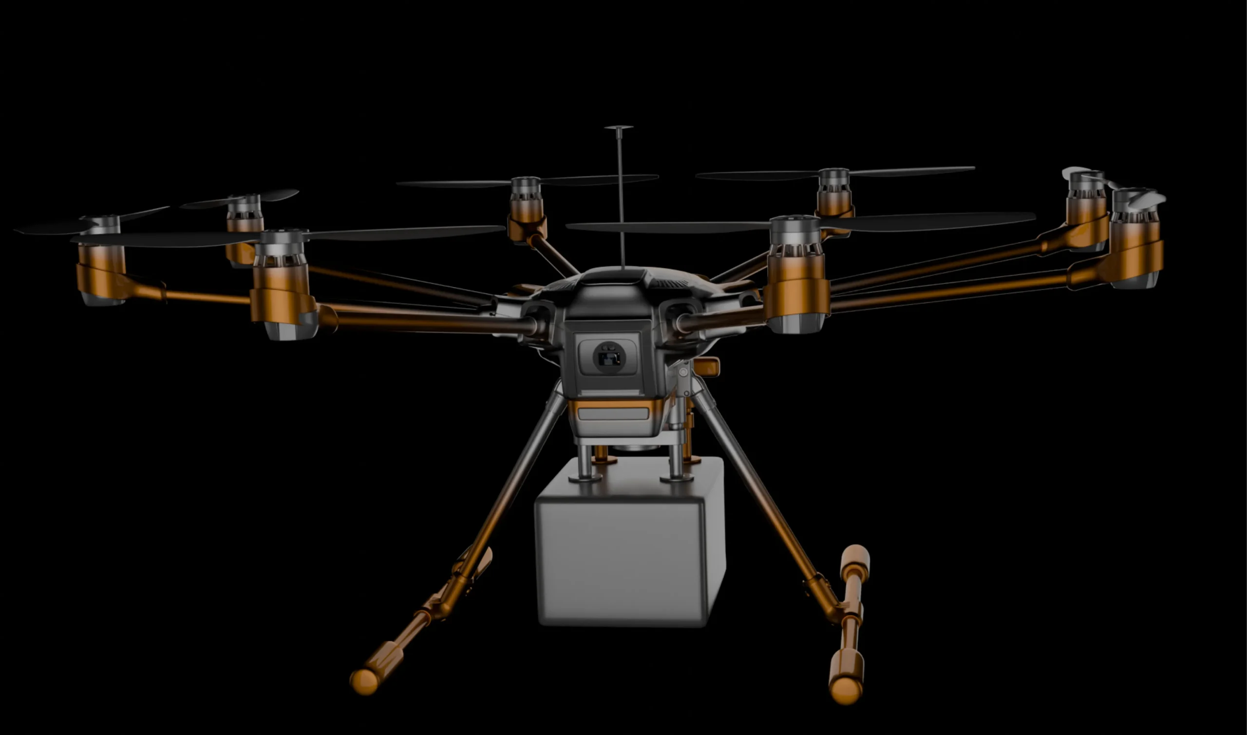
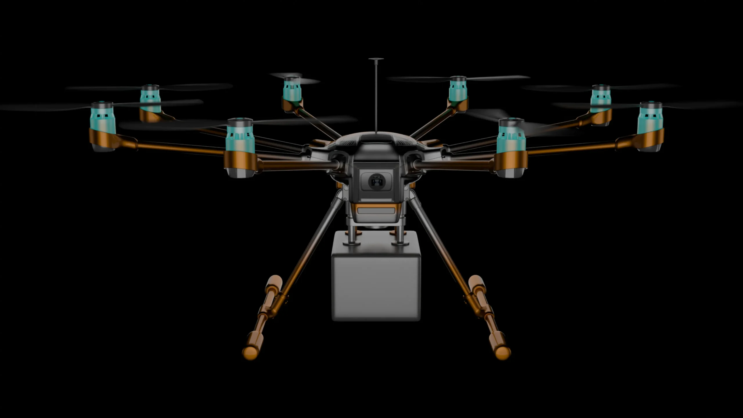
Drones (UAVs) are increasingly complex systems combining aerodynamics, control algorithms, and high-performance electric propulsion. Each drone’s propulsion uses brushless electric motors and inverters that must be validated before flight. Relying on real motors and propellers for testing has major drawbacks: it requires bulky test stands or dynos, incurs mechanical wear, and cannot safely explore fault or extreme conditions. As Impedyme explains, traditional setups (passive R-L loads or mechanical dynos) “fail to mimic real-world active power conditions” and “can’t return power to the inverter’s DC side”. In other words, you lose the loop-back energy and the fidelity needed to test flight controllers and ESCs under the actual loads seen in flight.
A hardware motor emulator overcomes these issues. It electrically replaces the physical motor, running a real-time model of the motor’s dynamics. This lets engineers inject precise torque/speed profiles, apply faults, or push an inverter to its limits without mechanical hardware. For drones, this means safely testing multicopter stability algorithms, thrust responses, or emergency behaviors in a lab. In practice, a motor emulator can be integrated into a Power-Hardware-in-the-Loop (PHIL) bench: the drone’s actual inverter/ESC and flight controller (the Device Under Test, DUT) are connected to the emulator, which replicates the motor, while a battery emulator provides DC power. All elements run synchronously. This approach accelerates development and improves safety: engineers can verify control firmware and motor performance without risking expensive propellers or bodily harm.
Impedyme’s motor emulator is specifically designed for this role. It is part of their Combined HIL and Power HIL (CHP) platform. In the following sections, we detail Impedyme’s technical features, supported motor types, integration steps for drone testing, and how it stands out against other “drone simulation” solutions.
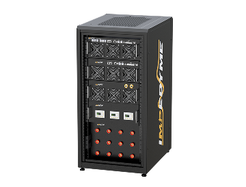
Impedyme Motor Emulator Platform: Architecture and Specs
Impedyme’s Motor Emulator (IME) is a fully electrical, FPGA-based system that reproduces the behavior of real electric machines in real time. Instead of relying on a physical dynamometer or a spinning motor, it electrically emulates exactly what a controller expects to see — closing the loop with production inverter hardware at full power and bandwidth.
The result is an ultra-high-fidelity, real-time emulation of electric machines that captures high-frequency effects most emulators miss — magnetic saturation, cogging-torque harmonics, and switching ripple. From small outrunner BLDCs to high-speed PM motors, IME lets teams develop, validate, and stress-test motor-drive systems across the full operating envelope, including ranges beyond typical EV traction drives.
1
The FPGA motor model updates every 90 ns (~11.1 MHz) — hundreds to over a thousand updates per electrical cycle, capturing saturation, cogging harmonics, and switching ripple.
2
A multilevel inverter and precision coupling network support up to 100 V DC-link and 80 A phase current, switching at 100 kHz for very low output ripple.
3
MotorSim Studio models PMSM, ASM, BLDC, and IPM machines — extensible and parameterized directly from CAD flux maps, inductance curves, and datasheets.
4
Faithfully reproduces high-speed BLDC and PM waveforms without clipping the controller’s signals, enabling accurate testing of advanced, high-speed drives.
Benefits of Drone Motor Emulation
Using a motor emulation drone setup offers several practical advantages. It shortens development cycles, lowers hardware risk, and makes tests repeatable across labs and teams. It also helps teams validate controller performance before flight — especially valuable when working with tight deadlines or expensive prototypes.

Faster Validation

Safer Testing

Repeatable Fault Injection
Deeper Insight

Less Prototype Wear

Consistent Across Teams
Use-Case Example: Drone Motor Controller Validation
As a concrete example, consider an R&D team developing a new quadcopter’s motor controller firmware. They need to validate that each ESC responds correctly to commands and that failure modes (e.g. phase loss) are handled gracefully. With Impedyme’s system, they would connect all four ESC outputs to a multi-channel motor emulator. The emulator runs four parallel BLDC models (one per motor). The battery emulator supplies each ESC. The team can then run automated test sequences: e.g., spin motors up to 6000 RPM, simulate a motor stall on one channel, inject voltage sags, and measure outcomes. The Controller’s logged telemetry (throttle outputs, fault flags) is correlated with the emulator’s instantaneous motor torques and back-EMFs. Problems can be diagnosed in detail, since every variable in the loop is observable and repeatable – something impossible with spinning props.
The Physical Realities of Drone Propulsion: Why Hardware Testing Requires a Motor Emulator Drone
Validating UAV propulsion systems involves balancing electrical efficiency, thermal management, and dynamic control loop stability. The ESC must precisely switch high-voltage DC into three-phase AC currents to drive the BLDC motor. Under heavy-lift or aggressive flight maneuvers, these components are consistently pushed to their physical boundaries.
High-Frequency Sensorless Field-Oriented Control (FOC)
While historical ESCs relied on six-step trapezoidal commutation, modern high-efficiency drones utilize sinusoidal feldorientierter Regelung (FOC). FOC minimizes torque ripple and acoustic signature while maximizing battery life, but it requires highly accurate, real-time tracking of the rotor's magnetic angle.
While historical ESCs relied on six-step trapezoidal commutation, modern high-efficiency drones utilize sinusoidal Field-Oriented Control (FOC). FOC minimizes torque ripple and acoustic signature while maximizing battery life, but it requires highly accurate, real-time tracking of the rotor's magnetic angle.
Low Inductance and High PWM Switching Speeds
High-power drone motors feature low stator inductance, which requires extremely high PWM switching frequencies—typically between 30 kHz and 60 kHz—to minimize current ripple. These high frequencies make the ESC vulnerable to electromagnetic interference (EMI) and fast thermal accumulation.
Optimizing the dead-time of the half-bridge MOSFETs and validating slew-rate controls to prevent shoot-through currents requires highly precise, high-bandwidth electrical measurements. These measurements cannot be reliably taken when physical motors are spinning, as they generate significant mechanical vibration and environmental noise.
Thermal Stress and Propulsion Failure Cascades
In industrial UAV configurations, ESCs are often mounted in enclosed, space-constrained compartments with limited airflow. Continuous high-throttle operation degrades the internal MOSFETs and capacitors over time, leading to gradual hardware degradation.
Under severe stress, an ESC can suffer from desynchronization, which causes sudden motor "twitching," loss of lift, or catastrophic thermal runaway. Replicating these thermal-electrical stress profiles on a physical test bench using real motors is highly dangerous and expensive, as failures often destroy the ESC and the motor under test.
| Physical ESC Component | Typical Test Challenge on Physical Bench | Risk of Physical Testing | Emulation Solution |
|---|---|---|---|
| MOSFET Power Stage | Measuring switching losses and thermal limits at 60 kHz PWM. | Direct short circuits can destroy the entire ESC and motor. | Active, non-rotating load emulates electrical switching behavior. |
| Sensorless Estimator | Verifying rotor position estimation under sudden load changes. | Loss of sync can cause motor stall and test rig damage. | Dynamic, sub-microsecond back-EMF modeling on real-time FPGAs. |
| Phase Wiring & Connectors | Diagnosing intermittent loose solder joints or cable degradation. | Unpredictable physical failures make diagnostics difficult to repeat. | Software-driven, programmable fault injection of phase loss and shorts. |
| DC Bus Capacitor | Measuring voltage ripple during rapid motor acceleration. | Overvoltage spikes can damage the battery pack and power supply. | 4-quadrant active power recirculation absorbs and returns energy. |
DroneSim Studio: The Software-Simulation Companion to the Motor Emulator
The design and authoring environment that feeds the high-fidelity hardware bench downstream. Tune the model, size the airframe, characterize the prop and confirm your control logic flies — nothing at risk, iteration fast.
Motor Modeling
Configure PMSM and other motor models with detailed electrical and mechanical parameters — accurately reproducing propulsion behavior before hardware testing begins.
Airframe Dynamics
Define mass, inertia, arm geometry, and propeller characteristics to simulate realistic drone motion, stability, and flight performance.
Real-Time Visualization
Monitor altitude, speed, rotor RPM, thrust, and vehicle attitude in a live 3D environment — instantly visualizing the impact of every parameter change.
Hardware-Ready Validation
Share validated motor models directly with the Motor Emulator, enabling a seamless transition from software simulation to hardware-in-the-loop testing.
Impedyme Motor Emulator in Drone Testing
1
Propulsion system validation
Multicopter propulsion and tiltrotor stability testing — autopilot response to motor failures, coordinated-flight algorithms, efficiency at speed, all without spinning props.
2
Multicopter thrust testing
Connect ESCs to the emulator running a model of motors + propellers. Map thrust vs. speed and analyze efficiency under controlled air-density and drag variations.
3
Fault injection scenarios
Simulate a sudden stall or short-circuit, or introduce asymmetry to watch the flight controller compensate — purely electrical, so even destructive faults are safe.
4
Closed-loop control HIL
Run PX4 or ArduPilot firmware on the Impedyme HIL/RCP-Box
while the emulator provides real-time motor response — verifying complex control laws in a hardware-like environment.
5
Environmental stress
Emulate temperature or supply fluctuations through MotorSim or the Batterie-Emulator to test control robustness against non-ideal conditions.
6
Beyond propulsion
Tiltrotor rotor + pusher channels emulated independently; brushless-driven tilt mechanisms and gimbals simulated for stability. Any UAV motor drive applies.
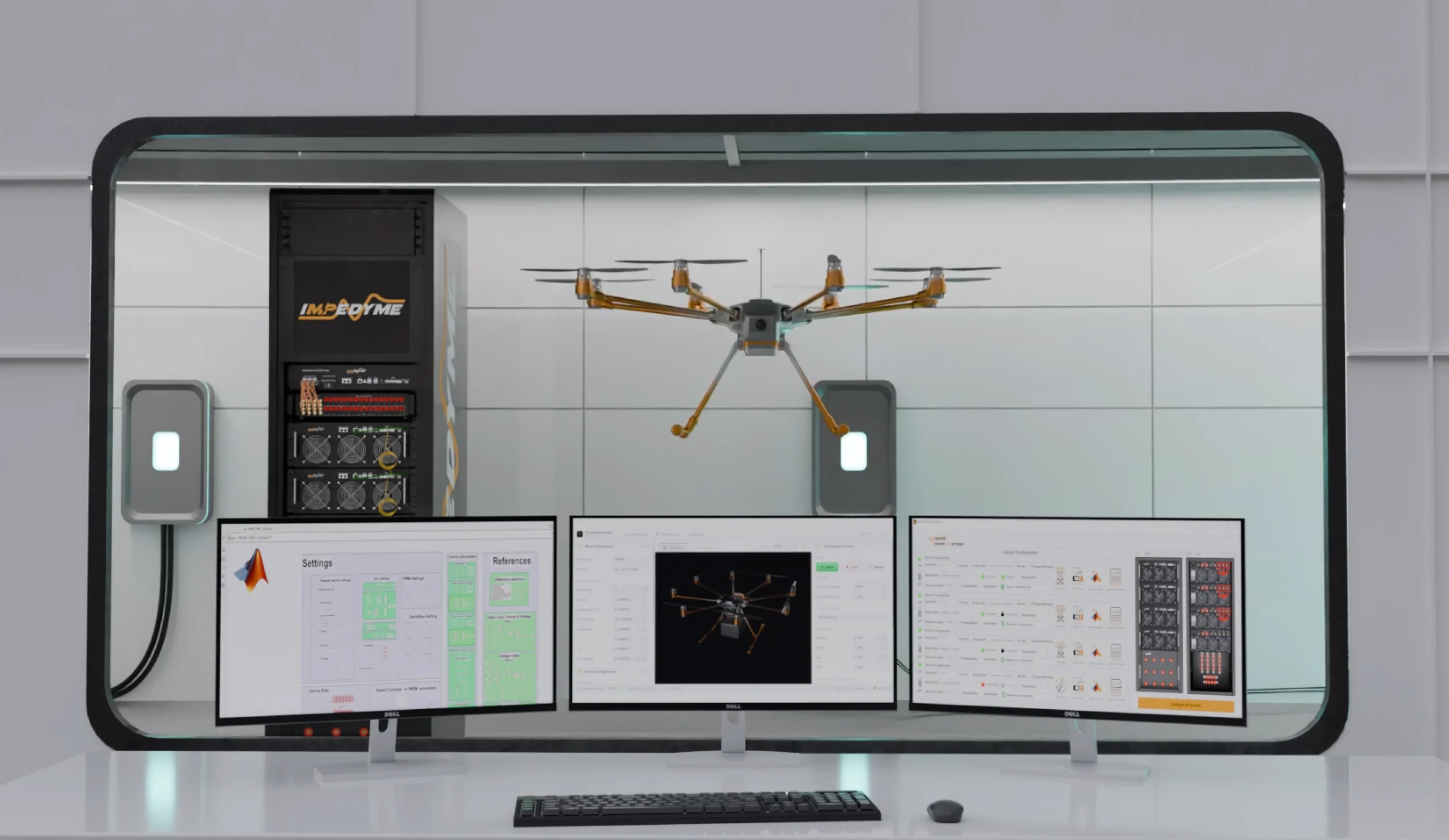
Testing Drone Motor Controllers with Power Hardware-in-the-Loop (PHIL)
Power Hardware-in-the-Loop (PHIL) testing lets engineers safely validate a drone's Electronic Speed Controller (ESC) without spinning a real propeller. The ESC connects to a motor emulator that tricks it into thinking it's flying: a Pixhawk autopilot sends speed commands, the Impedyme CHP 150 Power Cabinet absorbs power like a real motor, and the Impedyme HIL/RCP-Box solves motor-physics equations every microsecond to drive it—all monitored from a Control Studio workstation where engineers can trigger faults to test safety features.
Powering up & starting the motor
The autopilot is fed simulated flight data, making it think the drone is mid-air.
It calculates how fast the motors must spin and sends that command to the ESC.
The ESC sends out power; the cabinet measures it and the real-time brain instantly computes how a real motor would respond — a perfect feedback loop.
Simulating heavy wind & acceleration
The autopilot commands a sudden burst of throttle to simulate a rapid climb.
The simulator instantly calculates the heavy propeller drag a real drone would experience.
Engineers watch live graphs to ensure the ESC handles the power spike without overheating or shutting down.
Trapping & reusing braking energy
When a drone slows quickly, the motors become generators, pushing electricity backward into the system.
Instead of turning that into dangerous heat, the emulator safely returns the energy to the main power source.
Engineers can safely test aggressive braking algorithms with full 4-quadrant recirculation.
Simulating broken wires — fault injection
Using software, engineers instantly cut power to one motor phase; the emulator drops it to zero.
The ESC's internal brain must recognize the error and shut down within milliseconds.
Because it's entirely simulated, there's zero risk of hardware exploding if the test fails.
Use Cases for Drone Teams
A motor emulator solution supports drone development from conceptual design through hardware verification with fewer surprises, and is especially valuable for teams testing at scale or under repeated fault conditions. Common use cases include:
ESC validation & tuning
BLDC motor control testing
Drone powertrain fault testing
Controller algorithm development
Lab-based regression testing
Power electronics verification
Häufig gestellte Fragen
Ready to Transform Your Drone Motor Testing?
Join leading UAV manufacturers, aerospace engineers, and research institutions using Impedyme's real-time motor emulation platform for safe, accurate, and efficient drone propulsion testing.
Produkte