Motoremulator für Wechselrichter-Entwicklung
Die Entwicklung von Hochleistungs-Wechselrichter-Hardware für die elektrische Mobilität erfordert eine rigorose Validierung in realistischen Umgebungen. Bei Impedyme bieten wir hochmoderne Motoremulationswerkzeuge an, die Ingenieuren helfen, reale Bedingungen zu simulieren und den Entwicklungszyklus zu beschleunigen. Unsere Motoremulationssysteme gewährleisten unübertroffene Präzision und Effizienz für Tests während aller F&E-Phasen (Forschung und Entwicklung).
Warum die frühzeitige Wechselrichter-Hardwareentwicklung Motoremulation benötigt
Inverter-Hardware ist das Herzstück von Elektrofahrzeugen und verantwortlich für die Gleich-/Wechselstrom-Wandlung Motorsteuerung, sowie die Energieoptimierung. Allerdings stützen sich Tests in frühen Entwicklungsphasen häufig auf passive R-L-Lasten, was entscheidende Einschränkungen mit sich bringt, wenn keine Motoremulation zum Einsatz kommt: Eingeschränkte Komponentenbelastung: Passive Lasten beaufschlagen den Wechselrichter lediglich mit Blindleistung (Q), können jedoch die realen Bedingungen der Wirkleistung (P) nicht nachbilden. Dies verhindert eine präzise Prüfung von Schlüsselkomponenten wie Dioden und Schaltern und birgt das Risiko unentdeckter Schwachstellen.Inaktiver Gleichstrompfad (DC-Pfad): Passive R-L-Aufbauten können keine Energie auf die Gleichstromseite (DC-Seite) des Wechselrichters zurückspeisen. Dies schränkt die Fähigkeit stark ein, realitätsgetreues Leistungsflussverhalten und die damit verbundenen Effekte zu replizieren.
Leistungsprüfung mit dem Impedyme CHP Motoremulator
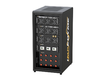
Der Impedyme CHP Motoremulator ist ein aktives, programmierbares System, das für die präzise Prüfung von Wechselrichter-Hardware entwickelt wurde. Es ermöglicht eine funktionale Validierung unter realen Spannungs- und Strombedingungen und bietet somit eine realistischere und detailliertere Testumgebung als herkömmliche induktive Aufbauten. Unsere Motoremulationsplattform, die speziell für moderne elektrische Antriebsstränge konzipiert wurde, gewährleistet präzise und zuverlässige Prüfergebnisse.

Niedrigleistungs-Signalemulation von Motoren mittels der RCP Box
Die Wechselrichterentwicklung in der Frühphase ist oft mit hohen Unsicherheiten verbunden. Die Impedyme RCP Box ermöglicht die Motoremulation auf Signalebene. Dies erlaubt Ihnen, unmodifizierte Steuerungshardware mittels einer hochpräzisen Echtzeitsimulation zu testen – ohne physische Komponenten zu riskieren.
Schnelle Inbetriebnahme des Prüflings (UUT): Profitieren Sie von einer einfachen Testeinrichtung, bei der lediglich vier Parameter zur Definition benötigt werden, um mit dem Prüfprozess zu beginnen.
Schnelle Parametrierung: Passen Sie mehrere Parameter, wie z.B. R und L, einfach und schnell per Mausklick während des Betriebs an.
Minimale Anlagenanforderungen: Für den Betrieb ist lediglich ein 5kW-Wechselstromanschluss (AC) erforderlich. Es wird kein Wasseranschluss für die Kühlung benötigt, da das System über eine eigenständige Flüssigkeitskühlung verfügt und ohne externen Chiller auskommt.
Realistische Leistungsemulation: Der Vier-Quadranten-Betrieb ermöglicht den vollen Drehmoment-/Drehzahl-Betrieb. Dies erlaubt die Wirkleistungsprüfung unter realitätsgetreuen Bedingungen.
Motoremulator-Prüfplattform: Von Signal- zu Leistungsebene: Mit den integrierten RCP- und CHP-Systemen von Impedyme können Ingenieure die Steuerungslogik auf der Signalebene validieren und nahtlos auf die Hochleistungsprüfung skalieren – alles innerhalb einer einheitlichen Plattform. So gewährleisten Sie eine vollständige Rückverfolgbarkeit und kompromisslose Performance über den gesamten Entwicklungszyklus hinweg.

Kann der Impedyme Motoremulator sowohl für Nieder- als auch Hochleistungsprüfungen verwendet werden?
Ja. Der Impedyme Motoremulator unterstützt sowohl die Prüfung auf Signalebene – mittels der Real-Time Control Prototyping (RCP) Box – als auch die Hardware-Emulation im Hochleistungsbereich mit dem CHP-System.Diese flexible Architektur ermöglicht es Ingenieuren, die Entwicklung vom Konzept bis zur Produktion zu rationalisieren, indem eine einheitliche Motoremulationsplattform genutzt wird.
Investieren Sie in den Impedyme Motoremulator, um die Wechselrichterentwicklung zu beschleunigen, die Testpräzision zu erhöhen und Ihre Elektromobilitätsprodukte schneller auf den Markt zu bringen – mit vollem Vertrauen in Leistung und Zuverlässigkeit.

Motor Emulator Testing Platform from Signal to Power
With Impedyme's integrated HIL/RCP Box and CHP systems, engineers can validate control logic at the signal level and scale seamlessly to high-power testing, all within one unified motor emulation platform. The same motor models and test cases carry forward from one stage to the next, which gives you full traceability and uncompromised performance throughout the development cycle.
Entwicklungsphase Impedyme Tool What You Validate
Concept and control design HIL/ RCP box (signal level) Control algorithms, protection logic, firmware
Controller hardware integration HIL/ RCP box (signal level) Unmodified controller hardware against a real-time motor model
Power stage bring-up CHP motor emulator (power level) Switching behavior, current control under real voltage and current
Full validation CHP motor emulator (power level) Full torque-speed range, regeneration, fault handling, component stress
This approach fits naturally into a wider Hardware-in-the-Loop strategy and complements the full Wechselrichtertest workflow, so motor emulation becomes one connected step rather than an isolated bench.
Who Uses Motor Emulation?
Impedyme's motor emulator platform serves teams that need realistic inverter testing without the cost and risk of rotating test benches:
- EV traction inverter developers validating drive inverters across the full vehicle operating range
- Industrial drive manufacturers testing variable-speed drives against different motor designs
- eVTOL and electric aircraft teams validating propulsion inverters where safety margins are critical
- Tier-1 suppliers and test labs that need repeatable, high-throughput validation for multiple customer programs
Passive Load vs Active Load vs Motor Emulator: Choosing the Right Fidelity Level
Inverter testing does not have to start with a motor emulator. Many teams begin with a passive load, move to an active load, and step up to motor emulation once the control system is involved. Each option sits at a different fidelity level. Knowing what each one can and cannot reproduce helps you choose the right tool for each stage of your test program.
Passive Last
Ein passive Last is a resistive load bank, sometimes combined with inductors, connected to the inverter's output. It absorbs the inverter's power and converts it into heat.
Passive loads are simple, low-cost and useful for:
- Basic power-up checks
- Burn-in testing
- Simple thermal soak tests
The limitation: a passive load has fixed electrical behavior. It cannot reproduce the back-EMF of a spinning motor, speed-dependent behavior, or the fast load changes a motor creates during acceleration and braking. It does not provide the dynamic load needed to properly test the inverter's switches, and because all the energy ends up as heat, it also adds cooling demand to the test cell.
Aktive Last
Ein aktive Last is an electronically controlled load that regulates how much current the inverter delivers. It is a clear step up from a passive load. You can set and change the load level, and you can load the inverter's switches hard enough to generate realistic heat at their junction points, which makes it useful for thermal and current-rating checks.
The limitation: an active load usually controls the level of current, most often the average or RMS value, rather than the exact shape of the current waveform. The waveform it produces may not match what a real motor would draw, including the ripple, phase relationships and transient behavior that the inverter's current controller responds to. An active load is a good tool for power and thermal stress, but it is not a substitute for a real motor when you are testing control behavior.
der Motor-Emulator
Ein Motoremulator reproduces the full electrical behavior of a motor at the inverter's terminals. A real-time motor model calculates the current a real machine would draw at every instant, and the emulator's power stage forces exactly that current, including back-EMF, saliency, saturation and load-torque effects.
Once the inverter's control system is part of the test, this precision becomes essential. To replace a real motor or dynamometer, the emulator's current must change faster than the inverter or controller samples it. When it does, the controller sees the same response it would see from a real machine, and its control loops behave exactly as they will in the final application.
Impedyme's FPGA-based CHP motor emulator is built for this level of fidelity.
Fidelity Level Comparison
Funktion Passive Last Aktive Last der Motor-Emulator
Funktionsweise Resistive (or resistive-inductive) load bank Electronically controlled current level Real-time motor model drives the exact motor current
Current waveform accuracy Fixed by load impedance Average or RMS controlled; waveform may not be correct Matches the real motor waveform
Dynamic load behavior Keine Begrenzt Full motor dynamics, including back-EMF and transients
Stress on inverter switches Low, not representative Realistic heat at junction points Realistic electrical and thermal stress
Control system testing No Begrenzt Yes; replaces motor and dynamometer
Fault testing Sehr begrenzt Begrenzt Simple, safe and reproducible
Energiehandhabung Converted to heat Depends on the load Four-quadrant operation, including regeneration
Typische Verwendung Power-up, burn-in, thermal soak Power and thermal stress tests Full inverter and control validation
Accelerate Inverter Development with the Impedyme Motor Emulator
Invest in the Impedyme motor emulator to accelerate inverter development, increase testing precision, and bring your electric mobility products to market faster, with full confidence in performance and reliability. By replacing passive loads and reducing reliance on dynamometers, you can start testing earlier, test more scenarios, and find problems while they are still easy to fix.
Häufig gestellte Fragen
Ready to Validate Your Inverter with a Motor Emulator Instead of a Dyno?
Discover how the Impedyme motor emulator delivers realistic power testing, faster commissioning, and safe fault validation.