Motor Emulator for Inverter Hardware Development
Developing high-performance inverter hardware for electrified mobility requires rigorous validation in realistic environments. At Impedyme, we offer state-of-the-art motor emulation tools that help engineers simulate real-world conditions and accelerate their development cycle. Our motor emulator systems provide unmatched accuracy and efficiency for testing during all R&D phases.
Why Early-Stage Inverter Hardware Design Needs Motor Emulation
Inverter hardware is the core of electric vehicles, handling DC/AC conversion, motor control, and energy optimization. However, early-stage testing often depends on passive R-L loads, which introduce key limitations when motor emulation is not used: Limited Component Stress: Passive loads apply only reactive power to the inverter, failing to mimic real-world active power conditions. This prevents accurate testing of components like diodes and switches, risking undetected vulnerabilities. Inactive DC Path: Passive R-L setups can’t return power to the inverter’s DC side, limiting the ability to replicate realistic power flow behavior.
Power-Level Testing with the Impedyme CHP Motor Emulator
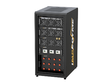
The Impedyme CHP motor emulator is an active, programmable system built for accurate inverter hardware testing. It delivers functional validation under real-world voltage and current conditions—offering a more realistic, detailed testing environment than conventional inductive setups. Designed for modern electric drivetrains, our motor emulation platform ensures precise, reliable results.

Low-Power Signal-Level Motor Emulation Using the RCP Box
Early-stage inverter development often involves high uncertainty. The Impedyme RCP box offers motor emulation at the signal level, allowing you to test unmodified controller hardware using high-fidelity real-time simulation—without risking physical components.
Fast UUT Commissioning: Enjoy easy test setup with only four parameters needing definition to begin the testing process.
Rapid Parameter Adjustment: Easily and quickly adjust several parameters, such as R and L, via a simple mouse click during operation.
Minimum Facility Requirements: Only a 5kW AC connection for power and no water connection for cooling is needed as the system is stand-alone liquid cooled without external chiller.
Realistic Power Emulation: Four-quadrant mode enables full torque/speed operation, allowing active power testing under true-to-life conditions.
Motor Emulator Testing Platform from Signal to Power: With Impedyme’s integrated RCP and CHP systems, engineers can validate control logic at the signal level and scale seamlessly to high-power testing—all within one unified platform. Ensure full traceability and uncompromised performance throughout the development cycle.

Can the Impedyme motor emulator be used for both low and high-power testing?
Yes. The Impedyme motor emulator supports both signal-level testing—using the Real-Time Control Prototyping (RCP) box—and high-power hardware emulation with the CHP system. This flexible architecture allows engineers to streamline development from concept to production, using one unified motor emulation platform.
Invest in the Impedyme Motor Emulator to accelerate inverter development, increase testing precision, and bring your electric mobility products to market faster—with full confidence in performance and reliability.

Motor Emulator Testing Platform from Signal to Power
With Impedyme's integrated HIL/RCP Box and CHP systems, engineers can validate control logic at the signal level and scale seamlessly to high-power testing, all within one unified motor emulation platform. The same motor models and test cases carry forward from one stage to the next, which gives you full traceability and uncompromised performance throughout the development cycle.
Development Stage Impedyme Tool What You Validate
Concept and control design HIL/ RCP box (signal level) Control algorithms, protection logic, firmware
Controller hardware integration HIL/ RCP box (signal level) Unmodified controller hardware against a real-time motor model
Power stage bring-up CHP motor emulator (power level) Switching behavior, current control under real voltage and current
Full validation CHP motor emulator (power level) Full torque-speed range, regeneration, fault handling, component stress
This approach fits naturally into a wider hardware-in-the-loop strategy and complements the full inverter test workflow, so motor emulation becomes one connected step rather than an isolated bench.
Who Uses Motor Emulation?
Impedyme's motor emulator platform serves teams that need realistic inverter testing without the cost and risk of rotating test benches:
- EV traction inverter developers validating drive inverters across the full vehicle operating range
- Industrial drive manufacturers testing variable-speed drives against different motor designs
- eVTOL and electric aircraft teams validating propulsion inverters where safety margins are critical
- Tier-1 suppliers and test labs that need repeatable, high-throughput validation for multiple customer programs
Passive Load vs Active Load vs Motor Emulator: Choosing the Right Fidelity Level
Inverter testing does not have to start with a motor emulator. Many teams begin with a passive load, move to an active load, and step up to motor emulation once the control system is involved. Each option sits at a different fidelity level. Knowing what each one can and cannot reproduce helps you choose the right tool for each stage of your test program.
Passive Load
A passive load is a resistive load bank, sometimes combined with inductors, connected to the inverter's output. It absorbs the inverter's power and converts it into heat.
Passive loads are simple, low-cost and useful for:
- Basic power-up checks
- Burn-in testing
- Simple thermal soak tests
The limitation: a passive load has fixed electrical behavior. It cannot reproduce the back-EMF of a spinning motor, speed-dependent behavior, or the fast load changes a motor creates during acceleration and braking. It does not provide the dynamic load needed to properly test the inverter's switches, and because all the energy ends up as heat, it also adds cooling demand to the test cell.
Active Load
An active load is an electronically controlled load that regulates how much current the inverter delivers. It is a clear step up from a passive load. You can set and change the load level, and you can load the inverter's switches hard enough to generate realistic heat at their junction points, which makes it useful for thermal and current-rating checks.
The limitation: an active load usually controls the level of current, most often the average or RMS value, rather than the exact shape of the current waveform. The waveform it produces may not match what a real motor would draw, including the ripple, phase relationships and transient behavior that the inverter's current controller responds to. An active load is a good tool for power and thermal stress, but it is not a substitute for a real motor when you are testing control behavior.
Motor Emulator
A motor emulator reproduces the full electrical behavior of a motor at the inverter's terminals. A real-time motor model calculates the current a real machine would draw at every instant, and the emulator's power stage forces exactly that current, including back-EMF, saliency, saturation and load-torque effects.
Once the inverter's control system is part of the test, this precision becomes essential. To replace a real motor or dynamometer, the emulator's current must change faster than the inverter or controller samples it. When it does, the controller sees the same response it would see from a real machine, and its control loops behave exactly as they will in the final application.
Impedyme's FPGA-based CHP motor emulator is built for this level of fidelity.
Fidelity Level Comparison
Feature Passive Load Active Load Motor Emulator
How it works Resistive (or resistive-inductive) load bank Electronically controlled current level Real-time motor model drives the exact motor current
Current waveform accuracy Fixed by load impedance Average or RMS controlled; waveform may not be correct Matches the real motor waveform
Dynamic load behavior None Limited Full motor dynamics, including back-EMF and transients
Stress on inverter switches Low, not representative Realistic heat at junction points Realistic electrical and thermal stress
Control system testing No Limited Yes; replaces motor and dynamometer
Fault testing Very limited Limited Simple, safe and reproducible
Energy handling Converted to heat Depends on the load Four-quadrant operation, including regeneration
Typical use Power-up, burn-in, thermal soak Power and thermal stress tests Full inverter and control validation
Accelerate Inverter Development with the Impedyme Motor Emulator
Invest in the Impedyme motor emulator to accelerate inverter development, increase testing precision, and bring your electric mobility products to market faster, with full confidence in performance and reliability. By replacing passive loads and reducing reliance on dynamometers, you can start testing earlier, test more scenarios, and find problems while they are still easy to fix.
Frequently Asked Questions
Ready to Validate Your Inverter with a Motor Emulator Instead of a Dyno?
Discover how the Impedyme motor emulator delivers realistic power testing, faster commissioning, and safe fault validation.