An induction machine is an AC electrical machine in which the rotor current is not supplied by wires or brushes but is induced by the rotating magnetic field of the stator, which makes the induction motor the most rugged, self-starting and economical way to turn electricity into motion. This guide explains what an induction motor is, the meaning of induction motor terminology, every major induction motor type, how ac induction motors are controlled and protected, how linear induction motors differ, and how modern engineering teams test an induction drive motor and its inverter without a spinning dynamometer.
The meaning of induction motor is right in the name: the stator winding acts like a transformer primary, and the rotor acts like a short-circuited secondary separated from it by an air gap. Alternating current in the stator creates a magnetic field that sweeps past the rotor conductors. That relative motion induces a voltage in the rotor, the voltage drives current around the shorted rotor circuit, and the current reacts with the field to produce torque.
Because energy crosses the air gap magnetically, a cage rotor needs no brushes, commutator or slip rings. Nothing electrical touches the rotating part, so there is nothing to wear out except the bearings.
Three properties made the induction machine the industrial default:
It has two built-in weaknesses that the rest of this article returns to:
A quick example shows the second point. A 4-pole machine on a 50 Hz supply has a field rotating at 1,500 rpm, yet the shaft at full load turns at about 1,460 rpm. On 60 Hz the field turns at 1,800 rpm and the shaft at about 1,750 rpm.
Scale matters too. The International Energy Agency describes electric motor-driven systems as the largest single end use of electricity, accounting for more than 40% of global electricity consumption, and IEA 4E Electric Motor Systems Platform puts the 2023 share at 53%, including 72% of electricity use in industry, with induction machines forming the workhorse of that fleet.
Every induction motor type works on the same principle. A rotating or travelling magnetic field induces current in the rotor, and that current produces torque. They differ in how the rotor is built and in how many supply phases feed the stator. Engineers usually group induction machines in these two ways. A few special forms, such as linear induction motors and doubly-fed machines, are built for particular jobs.
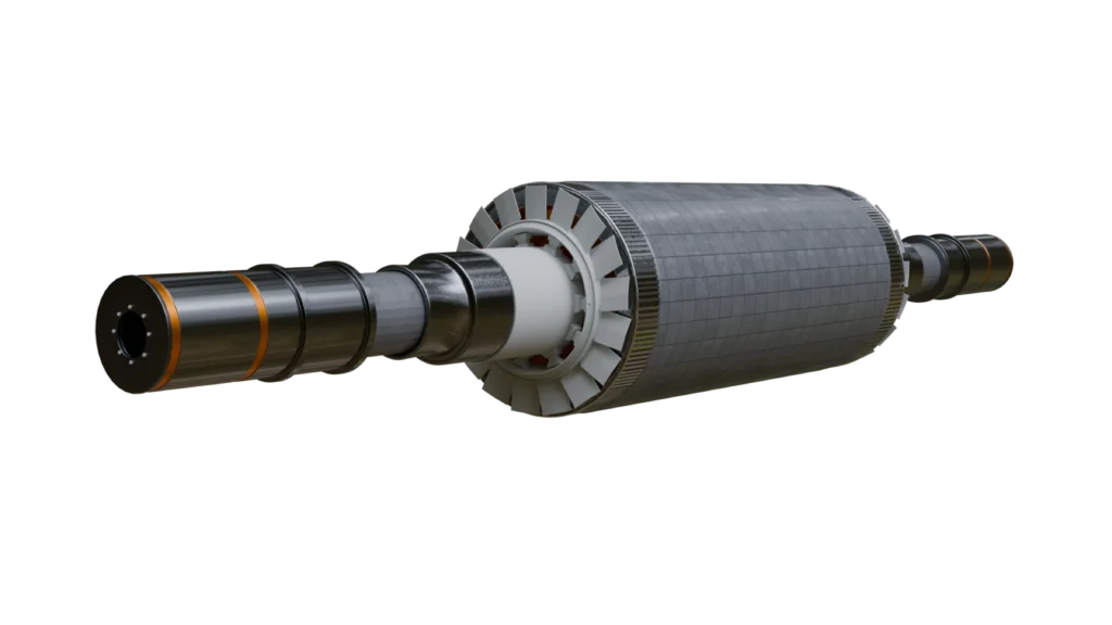
Squirrel-cage rotor. This is the most common design by a wide margin. Aluminium or copper bars sit in the rotor slots, and end rings short them together at both ends. There are no brushes, slip rings or rotor connections, so the motor is rugged, cheap to build and needs very little maintenance. The shape of the rotor bars largely sets how the motor behaves. Shallow bars give low slip and high running efficiency. Deep bars or a double cage give stronger starting torque, because at standstill the rotor current crowds toward the surface of each bar and the rotor’s effective resistance rises.
The NEMA MG 1 standard uses this bar-shape trade-off to define design letters for cage motors:
The IEC 60034-12 standard groups motors the same way, with design N for normal starting torque and design H for high starting torque.
Wound rotor (slip-ring). In this design the rotor carries a three-phase winding instead of bars. The winding is brought out through slip rings and brushes to external resistors. Adding resistance at start-up gives high starting torque and lowers inrush current. Once the motor is up to speed, the resistors are shorted out. Wound-rotor machines are used for very high-inertia loads. They are also the basis of the doubly-fed induction generator, where a power converter on the rotor circuit replaces the resistors. The cost of this flexibility is regular brush and slip-ring maintenance.
Polyphase machines. A three phase induction motor produces a rotating field of constant strength directly from its stator windings. That makes it self-starting, smooth-running and efficient. It is the standard choice for industrial drives, pumps, compressors, conveyors, HVAC plant and inverter-fed EV and rail traction, and most of this article applies to it.
Single-phase machines. A single phase induction motor’s main winding produces only a pulsating field, which on its own cannot start the rotor. Each variant adds a different way to create a starting field:
Single-phase machine dominate household appliances and light commercial equipment, where only a single-phase supply is available.
The vocabulary is confusing, so here is the short version:
One machine, three operating modes, separated by the sign of slip (the fractional speed difference between field and rotor):
| Mode | Slip and rotor speed | Power flow |
|---|---|---|
| Motoring | Slip between 0 and 1; rotor runs below synchronous speed, in the same direction as the field | Electrical to mechanical |
| Generating | Negative slip; rotor runs above synchronous speed | Mechanical to electrical |
| Plugging / braking | Slip greater than 1; rotor turns opposite to the field | Both electrical and mechanical inputs are dissipated as heat in the rotor |
The torque-speed section below shows all three regions on one curve.
The working principle is a four-step chain, and each step is quantified in the subsections that follow:
The stator carries three windings displaced 120 electrical degrees in space, fed by currents displaced 120 degrees in time. Each winding on its own produces a field that only pulses back and forth along its axis. Added together, the three pulsating fields combine into a single field of constant strength that rotates smoothly at a fixed speed. Its magnitude is 1.5 times the peak field of any one phase.
Snapshots make this concrete. At the instant phase A current is at its positive peak (0 degrees), the resultant field points along the axis of winding A. One third of a cycle later (120 degrees), phase B is at its peak and the field points along winding B. After another third (240 degrees), it points along winding C. The field has rotated one full pole pair in one electrical cycle without changing size.
Swap any two supply leads and the phase sequence reverses, so the field, and the motor, runs the other way. This is how reversing contactors work.
A single-phase winding cannot do this. It produces a pulsating field that is mathematically equivalent to two equal fields rotating in opposite directions. At standstill their torques cancel, so a single-phase induction motor has no starting torque. Designers add an auxiliary winding with a phase shift (from resistance or a capacitor) or a shading coil to create a weak rotating component that gets the rotor moving.
The speed of the rotating field, called synchronous speed, depends on only two things: supply frequency and the number of poles. It rises in direct proportion to frequency and falls as the pole count rises. In rpm, it equals 120 times the frequency divided by the number of poles; if you count pole pairs instead, it is 60 times the frequency divided by the pole pairs. This article counts total poles throughout.
A 4-pole machine therefore runs its field at 1,500 rpm on 50 Hz and 1,800 rpm on 60 Hz.
| Poles | 50 Hz synchronous speed (rpm) | 60 Hz synchronous speed (rpm) |
|---|---|---|
| 2 | 3,000 | 3,600 |
| 4 | 1,500 | 1,800 |
| 6 | 1,000 | 1,200 |
| 8 | 750 | 900 |
| 10 | 600 | 720 |
| 12 | 500 | 600 |
Because pole count is fixed when the machine is wound, the practical way to change speed is to change frequency. That is exactly what a variable-frequency drive (VFD) does.
Slip is the difference between synchronous speed and rotor speed, expressed as a fraction (or percentage) of synchronous speed.
The physics is simple. If the rotor ever reached synchronous speed, the bars would move in lockstep with the field. With no relative motion there is no change of flux, so no induced EMF, no rotor current and no torque. The rotor must lag the field just enough to generate the torque the load demands.
The frequency of the current in the rotor equals slip multiplied by supply frequency. Worked example: a 1,500 rpm field and a 1,460 rpm shaft give a speed difference of 40 rpm, a slip of 0.0267 (2.67%), and a rotor current frequency of only 1.33 Hz. That very low rotor frequency is why rotor iron losses are small in normal running.
| Machine size | Typical full-load slip |
|---|---|
| Fractional and small integral motors | Several percent |
| Medium general-purpose motors (NEMA Design A/B) | Less than 5% by definition in NEMA MG 1 |
| High-slip motors (NEMA Design D) | 5% or more by definition in NEMA MG 1 |
| Large, high-efficiency motors | Typically under 1% |
In the normal operating region, slip rises roughly in proportion to load. Maintenance engineers use this: comparing a tachometer reading against the nameplate full-load speed gives a quick estimate of how heavily a motor is loaded.
Torque depends on how much rotor current flows and how well it lines up in time with the air-gap flux. Both the rotor’s induced voltage and its frequency scale with slip. The rotor circuit has resistance, which does not change with slip, and leakage reactance, which grows with rotor frequency and therefore with slip.
The classic per-phase torque relationship combines these effects: torque grows with slip, with the square of the rotor induced voltage, and with rotor resistance, and is divided down by the rotor’s total impedance at that slip. One consequence is important for design: raising rotor resistance moves the peak (breakdown) torque to a higher slip, but does not change the size of that peak. That single fact explains wound-rotor starting resistors and the NEMA design letters described later.
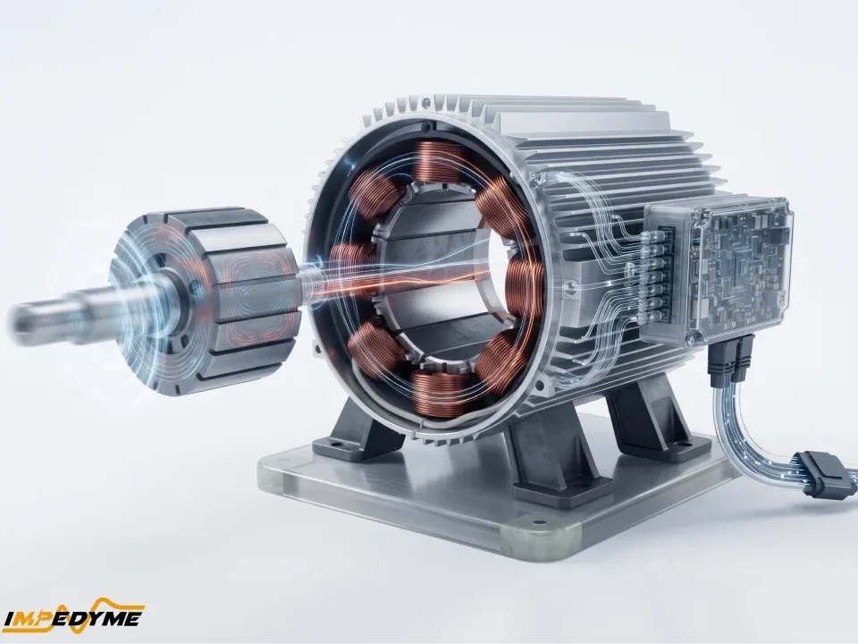
Every induction machine has two magnetic parts, the stationary stator and the rotating rotor, separated by a small air gap. The gap is kept as small as mechanical tolerances allow, because air is a poor magnetic path. A larger gap demands more magnetizing current to drive the same flux across it, which lowers power factor and raises stator copper loss.
The stator core is stacked from thin, insulated silicon-steel laminations to suppress eddy-current losses. Slots punched around the bore hold a distributed three-phase winding, connected in star (wye) or delta. The pole number is set by how the coils are grouped and connected. The winding insulation class (for example Class B, F or H) determines the allowable temperature rise. Machines fed from inverters need inverter-duty insulation, because fast PWM voltage edges and cable reflections create voltage spikes (high dv/dt) that stress turn-to-turn insulation; NEMA MG 1 Part 31 sets withstand requirements for definite-purpose inverter-fed motors.
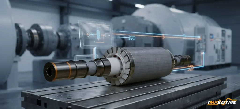
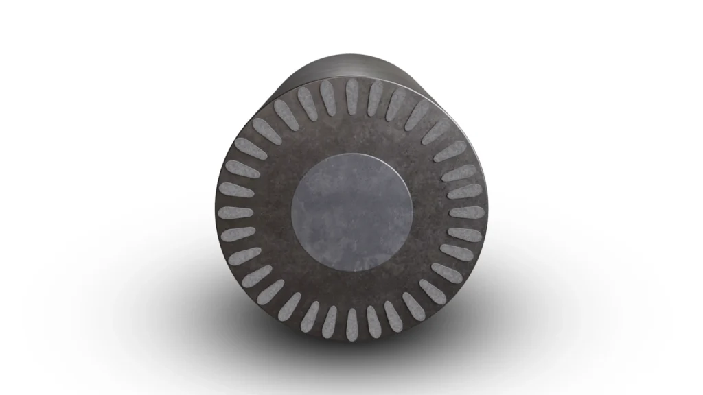
The most common rotor type is the squirrel cage: aluminum or copper bars, die-cast or fabricated into the slots of a laminated core, shorted at each end by end rings. The bars are usually skewed by about one slot pitch, which reduces cogging, magnetic noise and slot harmonics.
Bar shape is a powerful design tool. In deep-bar and double-cage rotors, the rotor current at standstill has the full supply frequency. Skin effect crowds that current to the outer part of the bar, so effective rotor resistance is high and starting torque improves. As the motor speeds up and rotor frequency falls, current spreads across the full bar, resistance drops and running efficiency recovers.
Copper rotor bars conduct better than aluminum, cutting rotor copper loss, which is one route manufacturers use to reach higher efficiency classes.
A wound rotor carries a three-phase winding similar to the stator’s, brought out through slip rings and brushes to external resistors. Adding resistance at start gives high starting torque with lower inrush current; the resistance is then shorted out for efficient running.
Today wound-rotor machines appear in two places: very high-inertia loads such as large mills and crushers, and the doubly-fed induction generator (DFIG) used in wind turbines, where a rotor-side power converter replaces the resistors and recovers slip power. The trade-off is brush and slip-ring maintenance that a cage rotor never needs.
Engineers analyze steady-state behavior with the per-phase equivalent circuit (often called the Steinmetz circuit), referred to the stator. It contains:
The trick of dividing rotor resistance by slip is what makes the circuit useful. That slip-dependent resistance can be split into two parts: the real rotor resistance, which represents rotor copper loss, and a fictitious load resistance that represents mechanical output.
The power-flow relationships follow in plain terms:
For peak torque, engineers replace the stator and magnetizing branch with a Thevenin equivalent. The slip at which breakdown torque occurs equals the referred rotor resistance divided by the magnitude of the total impedance looking back toward the source (Thevenin resistance plus the combined Thevenin and rotor leakage reactances). The size of the peak torque itself does not depend on rotor resistance, which confirms the design rule from the torque section.
| Parameter | How it is measured | Test reference |
|---|---|---|
| Stator resistance | DC resistance test, corrected to operating temperature | IEEE 112, IEC 60034-2-1 |
| Magnetizing reactance and core loss | No-load (light running) test at rated voltage | IEEE 112, IEC 60034-2-1 |
| Leakage reactances and rotor resistance | Locked-rotor test at reduced voltage, ideally at reduced frequency | IEEE 112 |
| Friction and windage | No-load test at reduced voltages, extrapolated to zero voltage | IEEE 112, IEC 60034-2-1 |
The torque-speed curve ties the whole subject together. Walking it from standstill to synchronous speed:
Beyond synchronous speed (negative slip) the curve continues into the generating region, where torque reverses and the machine pushes power back to the supply. Below zero speed (slip greater than 1) lies the braking or plugging region, used for rapid stops at the cost of heavy rotor heating.
Stability is decided where the motor curve crosses the load curve. On the steep running side, a small speed drop raises motor torque above load torque, so the system recovers; that is stable. On the low-speed side of breakdown, a speed drop reduces motor torque, so the motor decelerates further; that is unstable. A fan load, whose torque rises with the square of speed, crosses cleanly on the stable side. A constant-torque load such as a conveyor is less forgiving: if voltage sags enough that breakdown torque falls below the load, the motor stalls.
Load sharing: two motors on one shaft are forced to run at the same speed. The motor with the lower full-load slip (the stiffer curve) picks up a disproportionate share of the load. This is why mechanically coupled motors should be matched in slip characteristic.
Under volts-per-hertz control the curve shifts sideways. At each new frequency the curve keeps roughly the same shape, centered on the new synchronous speed, giving a family of parallel curves. The drive can therefore deliver near-rated torque at any speed up to base speed.
An ac induction machine magnetizes itself through its stator, so it always draws reactive current. That magnetizing current makes up most of the no-load current. The Electrical Apparatus Service Association notes that a 4-pole motor typically draws roughly one-third to somewhat over three-eighths of full-load current at no load, with higher fractions for motors with more poles.
Because magnetizing current stays roughly constant while load current falls, power factor and efficiency drop at light load. The U.S. Department of Energy notes that motors are usually designed to run at 50% to 100% of rated load, that maximum efficiency is usually near 75% of rated load, and that efficiency tends to decrease dramatically below about 50% load, with power factor dropping off sooner but less steeply. Oversizing a motor “for safety” therefore costs energy and power factor for its whole life.
Power-factor correction capacitors at the motor terminals supply the magnetizing vars locally. They must be sized below the motor’s no-load magnetizing requirement. If the capacitor bank is too large, a motor that keeps spinning after disconnection can self-excite as a generator, producing dangerous overvoltages and severe transient torques if it is reclosed onto the supply.
Efficiency is output power divided by input power. The losses are:
IEC 60034-30-1 defines international efficiency classes from IE1 (standard) through IE2 (high), IE3 (premium) and IE4 (super premium) to IE5 (ultra premium). The second edition, published in December 2025, formally introduced normative IE5 limits with new tables for 50 Hz and 60 Hz. Class limits vary with rated power, pole count and frequency, so always read them from the standard itself. Efficiency is measured according to IEC 60034-2-1 or IEEE 112; NEMA MG 1 references both.
At standstill (slip of 1) the rotor behaves like a short-circuited transformer secondary, so only leakage impedance limits current. Locked-rotor current is therefore a large multiple of rated current. NEMA MG 1 caps it for Designs B, C and D through maximum locked-rotor current tables and kVA code letters stamped on the nameplate, and notes that the first half-cycle peak can reach 1.8 to 2.8 times the tabulated RMS value.
On weak supplies this inrush causes voltage dips that can flicker lights, trip contactors or stall neighbouring motors. Starting methods trade inrush against starting torque:
| Starting method | How it works | Effect on starting current and torque |
|---|---|---|
| Direct-on-line (DOL) | Full voltage applied | Full locked-rotor current and torque; simplest and cheapest |
| Star-delta | Start in star, switch to delta | Line current and torque both cut to about one-third |
| Autotransformer | Reduced-voltage tap during start | Current and torque reduced; tap selectable |
| Primary resistor or reactor | Series impedance during start | Smooth but lossy reduction |
| Soft starter | Thyristors ramp the voltage | Adjustable ramp; torque still drops with voltage |
| Rotor resistance (wound rotor) | External resistors in rotor circuit | High torque with low current |
| VFD | Starts at low frequency and voltage | Rated torque near standstill at roughly rated current |
The key trade-off: with any reduced-voltage method, torque falls roughly with the square of voltage. NEMA MG 1 states this approximation directly. Starting at 80% voltage leaves about 64% of full-voltage torque, which may not be enough to break away a heavy load.
Speed can be changed through frequency (a VFD), pole number (pole-changing motors), slip (reducing voltage or adding rotor resistance, both lossy), or rotor power recovery (slip-energy recovery and the DFIG). Frequency control with a VFD now dominates. In modern systems the inverter, not the machine, sets the dynamic performance.
Keeping the ratio of voltage to frequency constant keeps the air-gap flux constant, so the motor can produce rated torque at any speed below base speed (constant-torque region). Above base speed the inverter cannot raise voltage further, flux falls as frequency rises, and the motor operates in field weakening at roughly constant power.
At very low speed, stator resistance drop becomes significant, so drives add a voltage boost (IR compensation). Slip compensation raises output frequency slightly as load increases to hold speed closer to setpoint. Open-loop volts-per-hertz control is entirely adequate for fans and pumps, and the energy savings can be large: by the affinity laws, the power a centrifugal fan or pump absorbs falls very steeply as speed is reduced, so slowing the motor beats throttling the flow.
Field-oriented control (FOC), or vector control, transforms the three stator currents (via the Clarke and Park transforms) into a two-axis frame rotating with the rotor flux. In that frame, one current component (direct axis) controls flux and the other (quadrature axis) controls torque, independently. The controller calculates the required slip frequency from the rotor time constant. The result is that the induction machine behaves like a separately excited DC machine, with fast, precise torque control.
Sensorless FOC replaces the shaft encoder with a flux observer or a model-reference adaptive system (MRAS) that estimates speed from terminal voltages and currents.
Yes. Drive the shaft above synchronous speed and slip becomes negative: air-gap power reverses and the machine delivers electrical power.
The catch is that it still needs reactive power to magnetize itself. When connected to the grid, the grid supplies it. When isolated, a capacitor bank plus residual magnetism in the rotor can build up voltage through self-excitation, but voltage and frequency then drift with load and speed, giving poor regulation.
Applications include small hydro plants, early fixed-speed wind turbines, DFIG wind turbines (where the rotor converter supplies excitation and enables variable speed), and regenerative braking in EVs and rail vehicles, where the drive pushes the machine into the generating region. Grid codes care about this behavior: an induction generator absorbs reactive power, and during a fault, when voltage collapses, it can lose excitation and draw heavily on the network’s reactive support during recovery.
Imagine cutting a rotary stator along one side and unrolling it flat. That is the primary of a linear induction motor (LIM). Its three-phase winding produces a travelling field rather than a rotating one, and the field induces currents in a conducting reaction plate (the secondary, often aluminum backed by steel), producing thrust.
The synchronous velocity of the travelling field equals twice the pole pitch multiplied by supply frequency. Worked example: a pole pitch of 0.25 m on 50 Hz gives 25 m/s, or 90 km/h.
Linear induction motors pay real penalties:
Applications include maglev and urban linear-metro rail and airport people movers — one supplier’s LIM technology drives New York’s JFK AirTrain, Vancouver’s SkyTrain Expo and Millennium Lines and Kuala Lumpur’s LRT System 2, and that supplier reports more than 700 LIM propulsion systems in operation — as well as conveyors and parcel sorters, launch systems and linear actuators. The honest engineering rule: use a LIM where direct linear thrust with no gears, wheels-for-traction or rotating parts justifies the lower efficiency.
A synchronous machine has no slip: its rotor is magnetized by a DC field winding or permanent magnets and locks to the rotating field.
| Attribute | Induction machine | Wound-field synchronous | Permanent-magnet synchronous (PMSM) |
|---|---|---|---|
| Rotor excitation | Induced from stator | DC field via slip rings or brushless exciter | Permanent magnets |
| Efficiency | Good; rotor copper loss is the main penalty | High, especially at large ratings | Highest at most operating points |
| Power density | Moderate | Moderate | Highest |
| Cost | Lowest | High | Moderate to high |
| Rare-earth dependency | None | None | Usually high |
| Spin losses when de-energized | Very low electromagnetic drag | Low | Magnet drag and back-EMF always present |
| Inverter fault behavior | No magnet back-EMF, so no uncontrolled fault current when flux decays | Field can be removed | Back-EMF can drive fault current at speed |
| Power factor | Lagging; worsens at light load | Adjustable, can lead | High |
| Control complexity | Moderate; needs slip estimation | Moderate | Moderate; needs rotor position |
Induction motors overheat for a short list of reasons:
| Fault | Signature | Detection method |
|---|---|---|
| Stator inter-turn short | Local hot spot, current unbalance, negative-sequence current | Surge testing, insulation resistance testing, current analysis |
| Broken rotor bars | Current sidebands either side of supply frequency, spaced from it by twice the slip frequency; torque and speed pulsations | Motor current signature analysis (MCSA) |
| Bearing failure | Rising vibration at bearing defect frequencies, noise, heat | Vibration analysis, temperature |
| Inverter-induced bearing currents | Electrical discharge pitting and fluting of races | Shaft-voltage measurement, inspection; mitigated by insulated bearings or shaft grounding per NEMA MG 1 Part 31 guidance |
| Air-gap eccentricity | Sidebands related to rotational frequency, unbalanced magnetic pull | MCSA, vibration analysis |
Classic machine testing is well established. Engineers measure DC winding resistance, run no-load and locked-rotor tests to identify the equivalent circuit, and determine efficiency on a load dynamometer according to IEC 60034-2-1 or IEEE 112.
But most engineering hours today go into testing the drive: the inverter hardware, its firmware and its protection logic. The modern workflow moves through three stages:
In PHIL, a motor emulator draws real inverter current according to a real-time induction-machine model. The inverter cannot tell it is not connected to a spinning machine, so engineers can test it across full load profiles, motoring, generating and braking, faults such as broken rotor bars or phase loss, and abuse conditions that would destroy a real machine, all without a dynamometer.
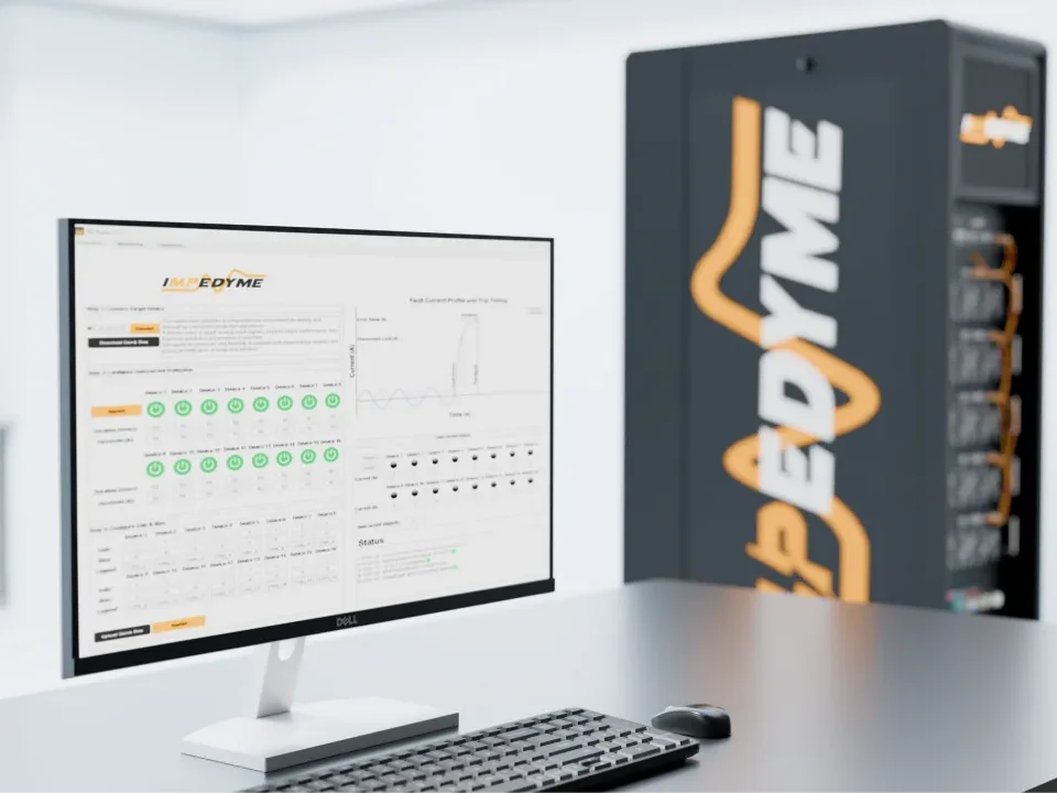
At Impedyme, we build this workflow around our FPGA-based CHP Series hardware platform and MotorSim Studio motor emulation software, which models induction (asynchronous) machines alongside PMSM, BLDC and IPM machines and supports fault injection. The HIL/RCP-Box covers signal-level controller testing, Impedyme-RT connects model-based design tools to the real-time hardware, and FPGA Scope captures fast internal signals. For EV traction inverters, our Real-Time Battery Emulator sits on the DC side, so both ends of the inverter see realistic, controllable behavior.
What changes for the test engineer:
The induction machine is still the workhorse of industry. If you’re asking what is induction motor technology, the answer is simple: a rotating stator field induces current in the rotor, and the rotor follows it without brushes or magnets. That simple meaning of induction motor operation is why induction machines run everything from pumps and conveyors to rail and EV traction.
The right induction motor type depends on the application. That could be a cage or wound rotor, a single-phase design, or one of the linear induction motors used for direct thrust. With modern drives and vector control, every AC induction motor becomes a precise, efficient induction drive motor, and the inverter that controls the AC induction machine needs testing just as rigorously as the motor.
What is the main induction motor type?
The main induction motor type is the three-phase squirrel-cage motor, used in most industrial drives. Other types include wound-rotor (slip-ring) motors for high-inertia starting, single-phase motors such as split-phase, capacitor-start, permanent split capacitor and shaded-pole designs for appliances, and special forms such as linear induction motors and doubly-fed machines.
Why is an induction machine called asynchronous?
It is called asynchronous because the rotor never turns at exactly the speed of the rotating magnetic field. Some speed difference, called slip, is needed so the field cuts the rotor bars and induces current. Without slip there is no rotor current and no torque, so the rotor always runs slightly behind synchronous speed when motoring.
Why does an induction motor overheat?
The common causes are overload, voltage unbalance, undervoltage, blocked cooling, too many starts and inverter harmonic losses. Voltage unbalance is especially damaging because current unbalance can be several times larger, and winding insulation life roughly halves for every 10°C rise in operating temperature.
What is a linear induction motor?
A linear induction motor is an induction machine unrolled flat. Its primary winding creates a travelling magnetic field that induces currents in a conducting reaction plate, producing straight-line thrust instead of torque. Linear induction motors power linear-metro and maglev systems, people movers, sorters and launch systems, accepting lower efficiency for direct linear motion.
AC induction motor vs PM motor: which is better?
Neither wins everywhere. A PM motor generally offers higher efficiency and power density, but depends on rare-earth magnets and has magnet drag and back-EMF when spinning unpowered. An AC induction motor is cheaper, magnet-free, tolerant of overloads and drag-free when de-energized, at the cost of magnetizing current and rotor losses.