half wave rectifier card

Application knowledgeGridMotorProduct knowledgeWebinars

half wave rectifier header

Half Wave Rectifier

A half wave rectifier is the simplest circuit that turns alternating current into direct current, and it does the job with a single diode. One half of the incoming AC cycle is allowed through to the load; the other half is blocked and discarded. That is the whole idea, and it explains both why the half wave rectifier appears in every introductory electronics course and why it has almost disappeared from serious power design. Searchers often arrive at this topic looking for a half bridge rectifier, and the two terms get used interchangeably even though they describe different circuits — so this guide covers the half wave rectifier properly, then sets out exactly how it relates to the half bridge rectifier and to the four-diode bridge. Along the way we cover the circuit, the cycle-by-cycle working, the capacitor filter, the standard performance figures, the problems the textbooks skip, and how a rectifier front end is validated once it exists in hardware. 


What Is a Half Wave Rectifier?

A half wave rectifier is a rectifier circuit that converts an AC input into a pulsating DC output by conducting during only one half of each input cycle. A single diode is placed in series between the source and the load. When the input drives the diode into forward bias, current flows and the load sees roughly the input waveform. When the input reverses, the diode is reverse biased, current stops, and the load sees nothing at all.

The output is therefore a train of positive humps separated by flat gaps. It is unidirectional, which technically makes it DC, but it is a long way from the steady rail that any real circuit needs. Half of the available energy is thrown away before the filter stage even begins.

That single-diode simplicity is the attraction. A half wave rectifier needs one cheap component, no centre-tapped transformer, and no matched device pairs. It is also the reason the circuit is the standard teaching example: everything a rectifier does can be explained without the bookkeeping that four diodes bring.


Half Wave Rectifier Circuit

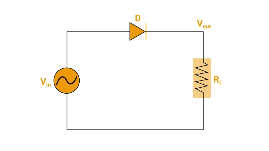
The half wave rectifier circuit has three elements. An AC source supplies the input, usually through a transformer that steps the mains down to a workable level and provides isolation. A single diode sits in series with the signal path and acts as the one-way valve. A load resistance completes the loop and develops the output voltage.

Everything about the circuit’s behaviour follows from the orientation of that one diode. Reverse the diode and the circuit still works, but it passes the negative half of the cycle instead and produces a negative output rail. Both arrangements are used in practice; the choice depends on which polarity the downstream circuit expects.

For analysis it helps to simplify the half wave rectifier diagram by replacing the transformer secondary with a plain voltage source. Nothing electrical changes, but the drawing collapses to a source, a diode, and a resistor, which makes the two half-cycles much easier to follow.

half bridge rectifier

How Does a Half Wave Rectifier Work?

A half wave rectifier works by exploiting the fact that a diode is not a resistor. It conducts readily in one direction and blocks in the other, so it behaves far more like a switch that is operated by the polarity of the applied voltage than like a passive component. Treating the diode as an ideal switch — closed when forward biased, open when reverse biased — gives a picture that is accurate enough for everything except loss calculations.

half bridge rectifier circuit

Positive Half Wave Rectifier Cycle

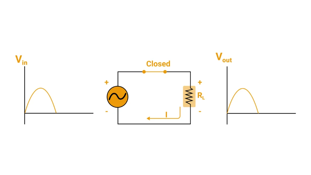
During the positive half wave rectifier cycle, the source drives the diode’s anode positive with respect to its cathode. The diode is forward biased and behaves as a closed switch. Current flows from the source, through the diode, through the load, and back to the source.

half wave rectifier positive

The load voltage tracks the input almost exactly, sitting one forward drop below it. For a standard silicon diode that drop is around 0.7 V and is constant enough to treat as fixed; a Schottky device drops roughly half that. On a mains-derived rail of tens of volts the loss is a rounding error, but on a 5 V rail it removes a meaningful slice of the output, which is why low-voltage designs almost always reach for Schottky parts.

Negative Half Wave Rectifier Cycle

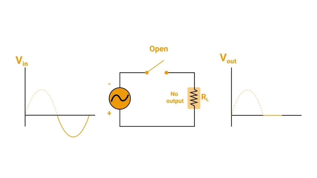
During the negative half wave rectifier cycle, the source polarity reverses. The diode’s cathode is now positive with respect to its anode, the device is reverse biased, and it behaves as an open switch.

half wave rectifier negetive

No current flows to the load, so the output voltage is zero for the entire negative half. The full reverse voltage appears across the diode instead, and the peak value of that reverse voltage is the number that governs which diode is safe to fit — a point we return to when sizing the device.

A small reverse leakage current does flow in a real diode, but it is measured in microamps and has no practical effect on the output. What does matter is that the diode must survive the reverse stress on every cycle, indefinitely.

Half Wave Rectifier Waveform: Input Against Output

Plotting the input and output together makes the cost of the circuit obvious. The input is a symmetrical sine wave, swinging equally positive and negative. The half wave rectifier waveform at the output keeps the positive humps and replaces the negative ones with flat stretches of zero.

Two consequences follow, and both are more important than they first appear.

First, the output ripples at the same frequency as the supply. A 50 Hz mains input produces 50 Hz ripple; a 60 Hz input produces 60 Hz ripple. This is the single most diagnostically useful fact in the whole topic, because a full-wave circuit ripples at twice the supply frequency. Ripple frequency alone tells you which kind of rectification you are actually looking at, regardless of what the schematic claims.

Second, the gaps are as long as the conducting periods. Any smoothing element has to hold the output up for a full half cycle with no help from the source, which makes the filtering job roughly twice as hard as it would be for a full-wave circuit delivering the same current.

Half Wave Rectifier with a Capacitor Filter

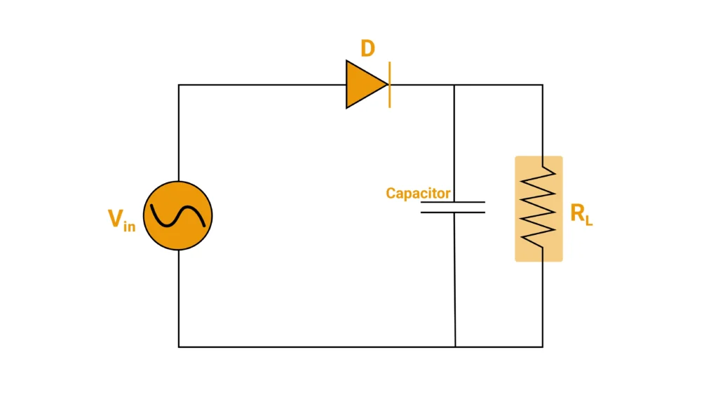
Raw half wave rectifier output is unusable as a supply rail. Adding a capacitor in parallel with the load turns it into something that can at least power an undemanding circuit.

half wave rectifier (Capacitor)

Working of the Half Wave Rectifier with Filter

The capacitor charges while the diode conducts and discharges into the load while the diode is blocking. Near the peak of the positive half cycle the source voltage exceeds the capacitor voltage, the diode conducts, and the capacitor charges rapidly to close to the peak value. As the input falls away past the peak, the capacitor voltage becomes the higher of the two, the diode turns off, and the capacitor is left alone to supply the load.

It discharges gradually, and how far it falls before the next peak arrives determines the ripple. A large capacitance or a light load means a small droop and a reasonably smooth rail. A small capacitance or a heavy load means the voltage sags a long way and the ripple becomes severe.

Adding the filter also changes the diode’s job completely. Instead of conducting for a full half cycle, it now conducts only for the short interval near each peak when the source exceeds the capacitor voltage. All the charge the load will consume over an entire cycle has to be delivered in that brief window, so the peak current through the diode is many times the average load current. On first power-up, with the capacitor fully discharged, the inrush is larger still. This is why a half wave rectifier with a capacitor filter can destroy a diode that looked comfortably rated on average current alone.


Half Wave Rectifier Formulas and Performance Figures

The half wave rectifier is characterised by four standard quantities. Rather than working through the derivations, here is what each one means and what value it settles at, because the numbers themselves are what tell the story.

Ripple Factor of Half Wave Rectifier

Ripple factor compares the size of the unwanted AC content in the output to the useful DC content. The ripple factor of a half wave rectifier is approximately 1.21.

That figure is worth pausing on. A ripple factor above 1 means the output contains more AC than DC — the unwanted component is larger than the thing you were trying to produce. By comparison, a full-wave circuit sits at about 0.48. This one number is the clearest statement of why the half wave rectifier is unsuitable for power supply work without heavy filtering.

Efficiency of Half Wave Rectifier

Rectification efficiency is the fraction of the input power that reaches the load as usable DC. The maximum theoretical efficiency of a half wave rectifier is about 40.6%, and real circuits fall short of that once diode losses and transformer resistance are counted.

The reason is not subtle. Half the input cycle is discarded outright, and the half that is kept is degraded by the diode’s forward drop. A full-wave circuit reaches roughly 81% because it uses both halves.

RMS Value of Half Wave Rectifier

The RMS value of a half wave rectifier output is one half of the peak input voltage. Because the waveform is present for only half of each cycle, its RMS value is lower than that of the sine wave that produced it — a full sine of the same peak has an RMS value of about 0.707 of the peak.

The average, or DC, value of the output is lower still, at roughly 0.318 of the peak. That average is what a DC voltmeter reads and what the load actually experiences as a steady component.

Form Factor of a Half Wave Rectifier

Form factor is the ratio of the RMS value to the average value, and for a half wave rectifier it works out at about 1.57. The further this number sits above 1, the more peaked and less smooth the waveform is. A perfectly flat DC waveform would have a form factor of exactly 1.

One more figure is worth adding, because it governs transformer sizing: the transformer utilisation factor of a half wave rectifier is around 0.287. In plain terms, a transformer feeding a half wave rectifier delivers less than a third of the power it could deliver into a resistive load, so it must be substantially oversized for the DC output it supports.

A Worked Example

Take a transformer secondary of 12 V RMS feeding a half wave rectifier with a 1 kΩ load and a silicon diode.

The peak of a 12 V RMS sine is about 17 V. Subtracting the diode’s forward drop of roughly 0.7 V leaves about 16.3 V as the peak at the load. Applying the average value figure of 0.318 gives a DC output of about 5.2 V, and applying the RMS figure of 0.5 gives about 8.1 V RMS. With a 1 kΩ load, the average load current is a little over 5 mA. The diode must block the full 17 V peak on every negative half cycle, so a part rated at 50 V or more would be a sensible fit.

The gap between a 17 V peak and a 5.2 V average is the entire argument against this topology in a single line.

What Is the Difference Between Half Bridge and Full Bridge?

This is where the terminology needs straightening out, because the search terms and the engineering terms have drifted apart.

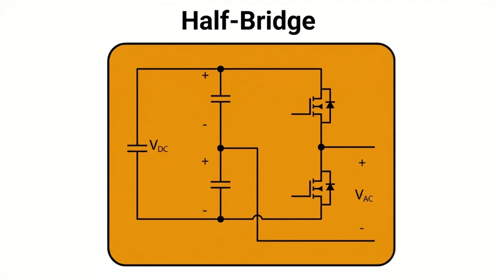
A half wave rectifier is not the same thing as a half bridge rectifier. A half wave rectifier is one diode in series with the load. A half bridge is one leg of two devices sharing a DC link, usually with a pair of split capacitors providing the midpoint. In a full bridge, two such legs are used, giving four devices in total.

The half bridge rectifier circuit is closely related to the half bridge inverter, and often the same hardware serves both roles. Because the switching devices carry body diodes and can be actively controlled, the leg can push power from DC to AC as an inverter or pull it from AC to DC as an active rectifier, depending on how it is driven. That reversibility is the reason half bridge legs are everywhere in modern converters and single-diode rectifiers are not.

The practical differences between full bridge rectifier vs half bridge rectifier arrangements come down to four things:

Half wave rectifierHalf bridgeFull bridge
DevicesOne diodeTwo devices in one legFour devices in two legs
Cycle usedOne half onlyBoth halves, with a split DC linkBoth halves, no split link
Output ripple frequencySame as supplyTwice supplyTwice supply
Voltage available to the loadPeak of the inputHalf the DC linkFull DC link
DC link capacitorsNot applicableSplit pair, midpoint requiredSingle bank
Typical useTeaching, signal detection, low-power biasCompact converters, low-power drivesMains front ends, chargers, drives

The term half wave bridge rectifier also circulates, and it is a contradiction: a bridge, by definition, uses both halves of the input cycle. Anyone searching that phrase almost always wants either the single-diode half wave rectifier described above or the four-diode bridge. It is worth knowing that the phrase is loose so that you can work out which circuit is actually meant.


What Is the Efficiency of a Half Wave Rectifier?

The efficiency of a half wave rectifier is approximately 40.6% at best, and lower in practice. Because only one half of each input cycle reaches the load and the diode drops voltage during the half it does pass, more than half the available input power never becomes usable DC. A full-wave arrangement roughly doubles this figure, reaching about 81%.

ParameterHalf wave rectifierWhat it means in practice
Average DC outputAbout 0.318 of peak inputA 17 V peak yields roughly 5.4 V of usable DC before losses
RMS output0.5 of peak inputHeating effect in the load is far below what the peak suggests
Ripple factorAbout 1.21More AC content than DC content — filtering is mandatory
Rectification efficiencyAbout 40.6% maximumOver half the input power is discarded
Form factorAbout 1.57The waveform is strongly peaked, not flat
Ripple frequencyEqual to supply frequencyThe key diagnostic signature of half-wave operation
Peak inverse voltageEqual to peak inputThe diode blocks the full peak every cycle
Transformer utilisationAbout 0.287The transformer must be heavily oversized

The DC Offset Problem Nobody Mentions

Every explanation of the half wave rectifier notes that the output is pulsating DC. Very few mention the consequence on the supply side, and it is the reason the topology is barred from most mains-connected equipment.

Because current flows for only one half of each cycle, the current drawn from the source is asymmetrical, and asymmetrical current contains a genuine DC component. If that source is a transformer, the DC component magnetises the core in one direction and never reverses it. The core’s operating point walks steadily towards saturation.

A saturating core does several unwelcome things at once. Magnetising current rises sharply, sometimes by an order of magnitude. Core losses and winding heating increase. The transformer becomes audibly noisy. Protection devices sized on expected load current start tripping for no apparent reason. And the transformer’s usable capacity collapses, which is exactly what the low transformer utilisation figure quoted earlier is telling you.

The same problem appears anywhere a half-wave load shares a supply with other equipment. DC injected into a distribution transformer or into a grid-connected system affects everything else on that supply, not only the circuit responsible. For equipment that must meet grid interconnection requirements, DC injection is an explicit limit with an explicit test, and half-wave conduction — whether by design or by a failed diode in a bridge — is its classic cause.

Harmonics and Power Quality

A half wave rectifier is a poor citizen on a shared supply for a second reason: its harmonic signature.

A full-wave bridge draws a symmetrical current, and symmetrical waveforms contain only odd harmonics. A half wave rectifier draws an asymmetrical current, so its spectrum contains a DC term and both even and odd harmonics.

Even harmonics are the awkward ones. Much of the equipment on a distribution system — transformers, metering, filters, protection relays — is designed around the assumption that load current is symmetrical between half cycles. Even-order content breaks that assumption. It couples into places odd harmonics do not, it complicates filter design because a filter tuned for odd harmonics does nothing for it, and it can confuse measurement equipment that averages over half cycles.

For a milliamp-scale signal detector this is irrelevant. For anything drawing meaningful current from a shared supply, it is disqualifying, and it explains why the half wave rectifier survives at low power and nowhere else.

Application of Half Wave Rectifier: Where They Are Actually Used

Textbook answers to this question tend to be dated. Here is where the half wave rectifier genuinely still earns its place.

Signal detection and demodulation. Envelope detection in AM receivers and RF signal detectors is the classic surviving application. The signal is tiny, efficiency is irrelevant, and the circuit’s job is to follow an envelope rather than deliver power.

Mains sensing and presence detection. Where a circuit needs to know whether the mains is live, or to derive a rough timing reference from it, a single diode and a high-value resistor do the job for pennies. Nothing downstream cares about ripple.

Low-power bias and standby rails. Small housekeeping supplies drawing a few milliamps, particularly standby rails that must stay alive when the main converter is shut down, are still built this way.

Energy scavenging front ends. RF and vibration harvesting circuits often use half-wave rectification simply because a second diode’s forward drop would consume a significant share of the tiny harvested voltage.

Snubber and clamp return paths. Inside converters, single diodes routinely steer energy from a clamp network back into a rail. This is half-wave rectification in everything but name.

Deliberate half-power switching. Putting a diode in series with a resistive load halves the delivered power. The trick appears in soldering iron standby modes and simple heater controls, where the resulting waveform is of no consequence.

As a failure signature. This one matters most on the bench. A four-diode bridge with one open diode stops being a bridge and becomes a half wave rectifier. Output falls, ripple grows, and — critically — ripple frequency halves. Recognising the half wave rectifier waveform where a full-wave one belongs is how the fault gets found.

Advantages and Disadvantages of the Half Wave Rectifier

Advantages

  • One diode, minimum component count and cost
  • No centre-tapped transformer and no matched device pairs required
  • Simple to build, analyse and teach
  • Easily reversed to produce a negative rail
  • Adequate wherever the load is tiny and ripple does not matter

Disadvantages

  • Ripple factor above 1 — more AC content than DC
  • Maximum efficiency around 40.6%
  • Ripple at supply frequency, requiring roughly twice the filtering of a full-wave circuit
  • Draws DC from the source, pushing transformers towards saturation
  • Poor transformer utilisation, forcing an oversized transformer
  • Injects both even and odd harmonics into a shared supply
  • Unsuitable for essentially all mains-connected power conversion

Choosing and Sizing the Diode

Four ratings decide whether a diode survives in a half wave rectifier.

Peak inverse voltage. The diode blocks the full peak of the input on every negative half cycle, so its reverse rating must exceed that peak. Mains-derived supplies carry transients well above the nominal peak, so a margin of at least two to one is normal practice rather than caution.

Average forward current. The published rating assumes a specific case temperature and mounting arrangement. Real installations run hotter than the datasheet conditions, so derate accordingly and check the junction temperature rather than trusting the headline number.

Surge current. With a capacitor filter fitted, the diode conducts in short high-current bursts near each peak, and the first cycle after power-up is worse still because the capacitor starts empty. The non-repetitive surge rating, not the average current rating, is what protects against that event.

Forward voltage drop. On a high-voltage rail this is negligible. On a low-voltage rail it is a significant share of the output and of the loss budget, which is why Schottky diodes dominate low-voltage rectification despite their higher reverse leakage and lower reverse voltage ratings.

Reverse recovery becomes relevant above mains frequency. At 50 or 60 Hz a standard rectifier diode is fine; in a switching converter operating at tens or hundreds of kilohertz, recovery losses can exceed conduction losses and a fast or ultrafast part becomes mandatory.

Testing and Troubleshooting a Rectifier Stage

Rectifier faults are common and the symptoms are consistent enough to diagnose quickly.

Check ripple frequency first. This is the fastest and most informative measurement available. A full-wave stage should ripple at twice the supply frequency. If it ripples at supply frequency, a diode has failed open and the circuit has degraded into a half wave rectifier. No other single measurement identifies the fault so directly.

Measure ripple under load, not at no load. A marginal rectifier or a dried-out filter capacitor can look acceptable unloaded and fall apart under current. Ripple amplitude that grows disproportionately with load points at either a failing capacitor or a diode conducting poorly.

Look for DC on the AC side. A clamp meter capable of measuring DC current on the supply feed will reveal half-wave conduction where it should not exist. Rising magnetising current, transformer heating and audible buzzing all support the same conclusion.

Use thermal imaging under load. A diode carrying more than its share, or one with an elevated forward drop, runs hot before it fails. In a bridge, an obvious thermal imbalance between devices is a reliable early warning.

Check reverse leakage on suspect devices. A diode that has been repeatedly stressed close to its reverse rating may not fail outright but will leak increasingly, degrading output and heating itself in the process.

Validating Rectifier Front Ends at System Level

A single diode is trivial in isolation. The behaviour that actually causes problems — DC offset drawn from the supply, harmonic injection, ripple interacting with a downstream converter, a rectifier stage degrading under thermal stress — only appears when the front end is exercised as part of a complete system, under a supply that is not a perfect sine wave and a load that is not a resistor.

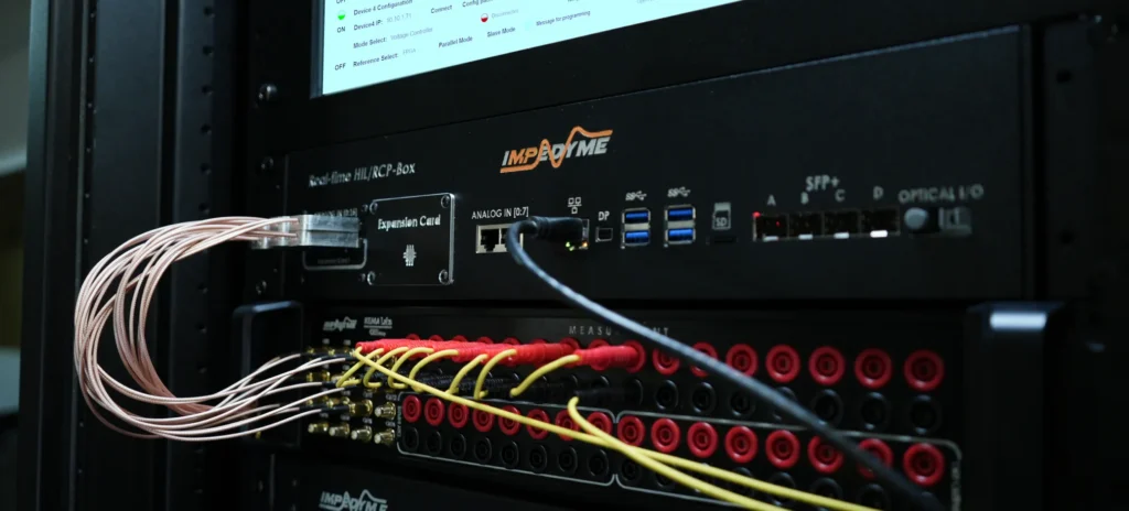
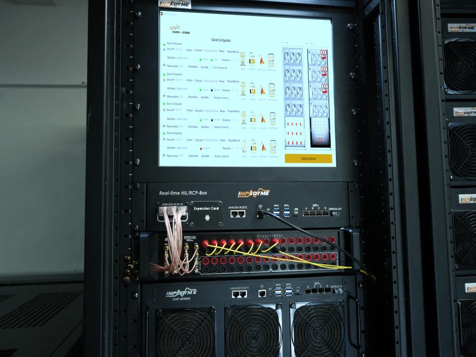
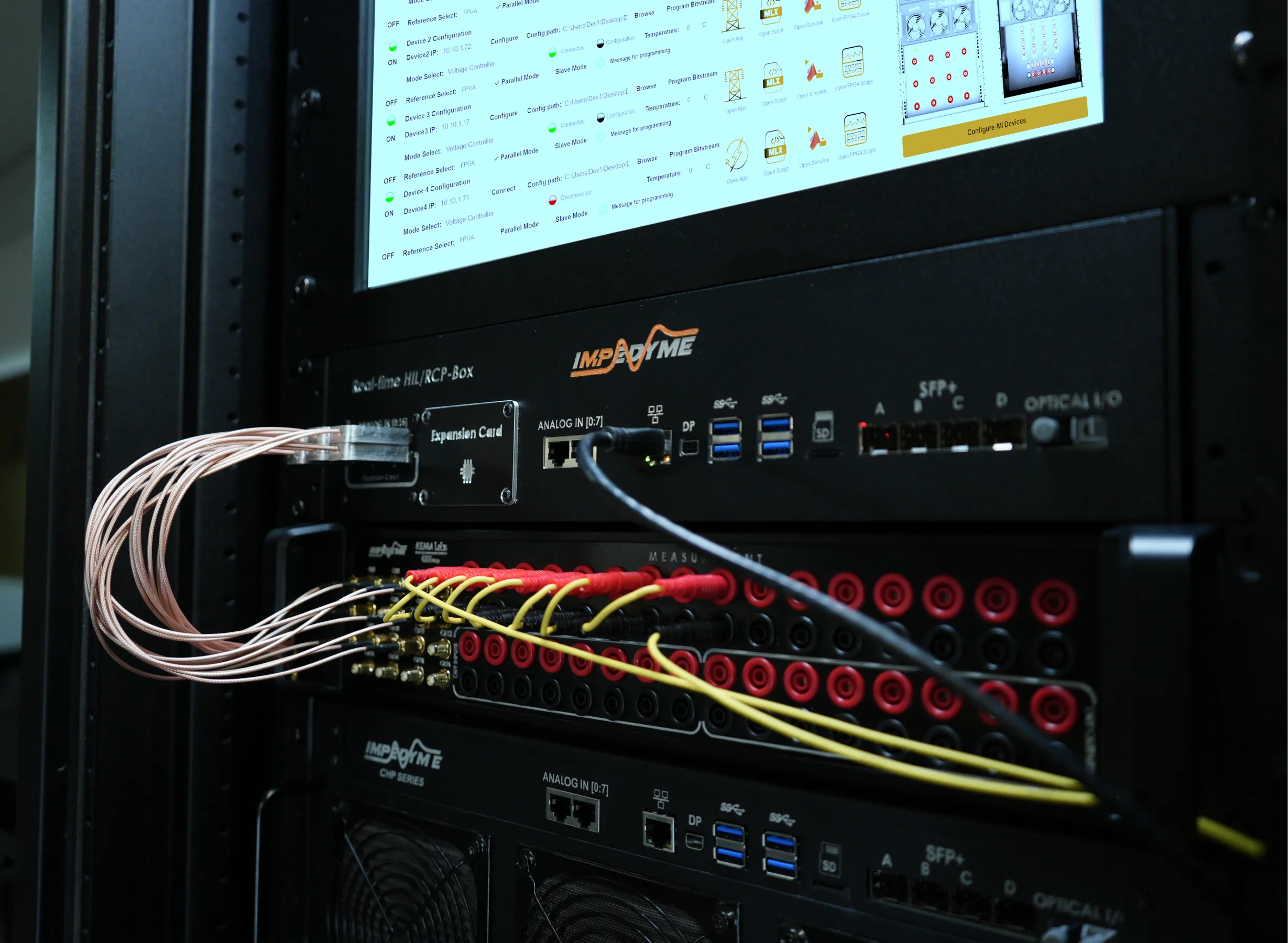
That is the gap between the analysis and the hardware, and it is what real-time simulation exists to close. At Impedyme we build platforms that let engineers put a physical converter front end against a simulated source and load at full power, so that its behaviour is observed rather than assumed.

Grid emulator is the part that matters most here. A rectifier that behaves impeccably on a clean laboratory supply may draw a very different current when presented with a distorted, sagging or unbalanced input, and that condition is exactly what the equipment will meet in service. Our GridSim Studio software and CHP Series platform let teams present those conditions deliberately and repeatably, including the DC injection scenarios that grid interconnection standards require to be tested. PowerHIL Studio extends the same approach to Power Hardware-in-the-Loop work, where the converter under test exchanges real power with a simulated system rather than a bench load.

The result is that front-end behaviour — the current signature, the harmonic content, the response to a disturbed supply — is characterised before the design is committed, not discovered during compliance testing.

Conclusion

The half wave rectifier is the clearest possible demonstration of how rectification works and one of the least suitable circuits for actually doing it. A single diode, one half of the cycle passed and one discarded, a ripple factor above 1, efficiency around 40%, and a supply-side DC component that pushes transformers towards saturation: the half wave rectifier circuit earns its place in teaching and in low-power signal work, and loses the argument everywhere else.

Knowing it properly still pays off. The half wave rectifier waveform is the signature of a failed bridge diode, and understanding why the circuit’s terminology overlaps with the half bridge rectifier saves a great deal of confusion when reading datasheets and search results. When it comes to full bridge rectifier vs half bridge rectifier decisions in real converter design, the half wave rectifier is best understood as the baseline that both of them exist to improve on.

Frequently Asked Questions 

What is the efficiency of a half wave rectifier?

The maximum theoretical efficiency of a half wave rectifier is about 40.6%, and practical circuits achieve less once diode and transformer losses are included. Half the input cycle is discarded and the diode’s forward drop reduces the remainder, so most of the input power never reaches the load.

Can a capacitor filter make a half wave rectifier smooth enough for a power supply?

For very light loads, yes. For anything drawing meaningful current, the capacitor must hold the output up for a full half cycle unaided, so it needs to be roughly twice the size required by a full-wave circuit, and the diode then faces high repetitive peak and inrush currents.

Why do half wave rectifiers cause transformer problems?

Because current flows on only one half cycle, the current drawn contains a DC component that magnetises the transformer core in one direction. The core drifts towards saturation, magnetising current and heating rise, the transformer may buzz audibly, and its usable capacity falls sharply.

How do you know if a rectifier diode has failed?

Check the ripple frequency. A full-wave stage should ripple at twice the supply frequency; if it ripples at supply frequency, a diode has failed open and the circuit is now working as a half wave rectifier. Confirm with ripple amplitude under load and thermal imaging of the devices.

What is the peak inverse voltage of a half wave rectifier?

The peak inverse voltage equals the peak value of the input voltage, because the full peak appears across the diode during the blocking half cycle. Mains transients can exceed the nominal peak considerably, so diodes are normally specified with at least twice the calculated reverse voltage.