solid state transformer card

Application knowledgeGridMotorProduct knowledge

solid state transformer header

Solid State Transformer (SST)

Table of Contents

Solid state transformer is a power-electronics-based device that converts medium-voltage AC into regulated low-voltage AC or DC using high-frequency switching and a compact medium-frequency transformer, replacing the bulky iron-and-copper magnetics of a conventional unit. In 2026, solid state transformers have moved from the lab bench toward real deployment, pushed by 800-volt DC data center architectures, megawatt EV charging, renewables and storage, and a distribution-transformer supply chain under severe lead-time pressure. This guide explains what an SST transformer is, how it works stage by stage, its structure and features, the semiconductors and controls inside it, how it compares with a conventional transformer, its architectures, its role on the power grid, its advantages and limitations, the emerging standards landscape, and how solid state transformers are validated before grid connection.

What Is a Solid State Transformer?

A solid state transformer is an AC-to-AC (or AC-to-DC) power converter that performs the voltage-changing job of a conventional transformer while adding active control, using power semiconductors and a high-frequency magnetic core. It is also called a power electronic transformer (PET), an electronic power transformer, or, in grid contexts, a “smart transformer.”

The three defining traits are a medium-voltage connection, medium-frequency isolation, and full controllability. An SST still contains a transformer — a small medium-frequency one that provides galvanic isolation and the voltage ratio — so “solid state” means power electronics have replaced the heavy line-frequency magnetics, not that the magnetics are gone entirely. Do not confuse an SST with a solid-state battery, a solid-state relay, or the small electronic transformers used in low-voltage lighting; those are unrelated technologies that share only the adjective.

Solid State Transformer Applications: Data Centers, EV Charging, PV, BESS, and More

Solid state transformers earn their keep wherever DC output, tight control, or a small footprint matters more than the lowest possible AC-to-AC loss. The application list is expanding quickly.

Data centers

AI compute racks are driving distribution toward 800 V DC (often implemented as ±400 V DC), with industry reference architectures for AI facilities now targeting on the order of 2 megawatts per rack row. An SST can convert a medium-voltage AC feed directly into a regulated DC bus at the edge of the facility, collapsing several conversion stages, cutting copper mass because higher voltage means lower current, and easing the transformer lead-time crunch that slows “speed to power.” See our notes on data center power stability and hyperscale data center interconnection.

EV charging

Medium-voltage-connected fast-charging hubs and heavy-duty depots use an SST to convert a utility feed (commonly in the 12–15 kV range) straight to a DC bus for chargers, replacing a step-down transformer, switchgear, and a separate rectifier with one compact, often liquid-cooled cabinet. Multiport designs can fold in on-site storage. This is closely related to HIL testing of an EV powertrain.

PV, BESS, and DC/AC loads

Photovoltaic arrays and battery energy storage systems are native DC resources; an SST’s DC port connects them with fewer conversion steps and bidirectional flow. Industrial plants use SSTs for controllable, high-quality power to sensitive processes, and the same device can serve conventional AC loads or a native DC bus.

Beyond the core set

Rail traction has long been a proving ground for medium-frequency power conversion; marine and shipboard DC distribution and hydrogen electrolysis plants are emerging fits,all of which benefit from the SST’s compactness and DC-friendly architecture.

sst transformer

How Does a Solid State Transformer Work?

At a high level, a solid state transformer works in three ordered steps:

  1. An active rectifier turns medium-voltage AC into a DC link.
  2. An isolated high-frequency DC-DC stage transfers power across a medium-frequency transformer.
  3. An inverter rebuilds low-voltage AC, or the DC link feeds DC loads directly.

Stage 1: Medium-voltage active rectifier

The front end is an active, controlled rectifier — an active front end, not a passive diode bridge. Because its switches are commanded rather than free-running, it draws near-sinusoidal current, controls power factor, and supports bidirectional flow. That controllability is the reason it replaces a simple full bridge rectifier built from diodes.

Stage 2: Isolated high-frequency DC-DC stage

The isolation and the voltage ratio live here, typically in a dual active bridge or an LLC/CLLC resonant converter. Both switch at high frequency and use a medium-frequency transformer for galvanic isolation. Because the magnetic core only has to store and transfer energy over a very short switching period, running it at high frequency lets it shrink dramatically compared with a 50/60 Hz core— the same power moves through far less iron and copper. This stage typically relies on a bidirectional DC-DC converter, and validating it well calls for careful DC-DC converter testing.

Stage 3: Inverter or DC port

The final stage either rebuilds clean low-voltage AC for conventional loads or presents a native DC bus, such as 800 V DC, directly to DC loads.

Switching at tens of kilohertz gives an SST something a passive transformer can never have: speed. It can sense a disturbance and respond within microseconds— actively limiting current, holding voltage, or riding through a sag — where a conventional transformer simply passes the disturbance through to whatever is downstream.

sst solid state transformer

Key components inside a solid state transformer

ComponentRoleDesign pressure
Power semiconductors (SiC MOSFETs; IGBTs in some designs)Do the high-frequency switching in every stageVoltage rating, switching loss, thermal limits, device supply
Medium-frequency transformerGalvanic isolation and voltage ratioInsulation, partial discharge, thermal management, core material
DC-link capacitorsBuffer energy between stages, stabilize the busRipple current, lifetime, size
Gate drivers and isolated auxiliary powerDrive the switches safely and cleanlyHigh dv/dt immunity, reinforced isolation, short-circuit protection
Sensing, control, and communicationsMeasure, decide, and coordinate the cellsBandwidth, latency, noise immunity, cybersecurity
Cooling and enclosureRemove heat and keep energized parts safePower density, ingress protection, serviceability

Solid State Transformer Structure: Inside a Packaged Medium-Voltage SST

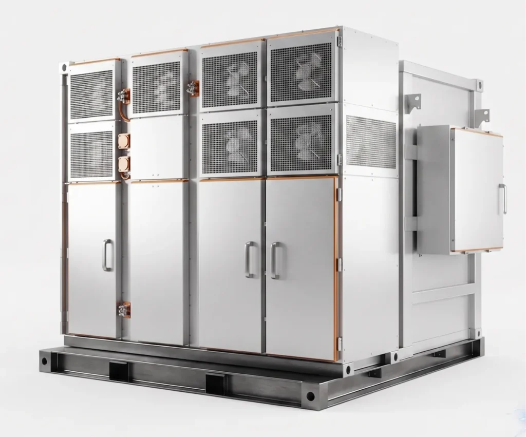
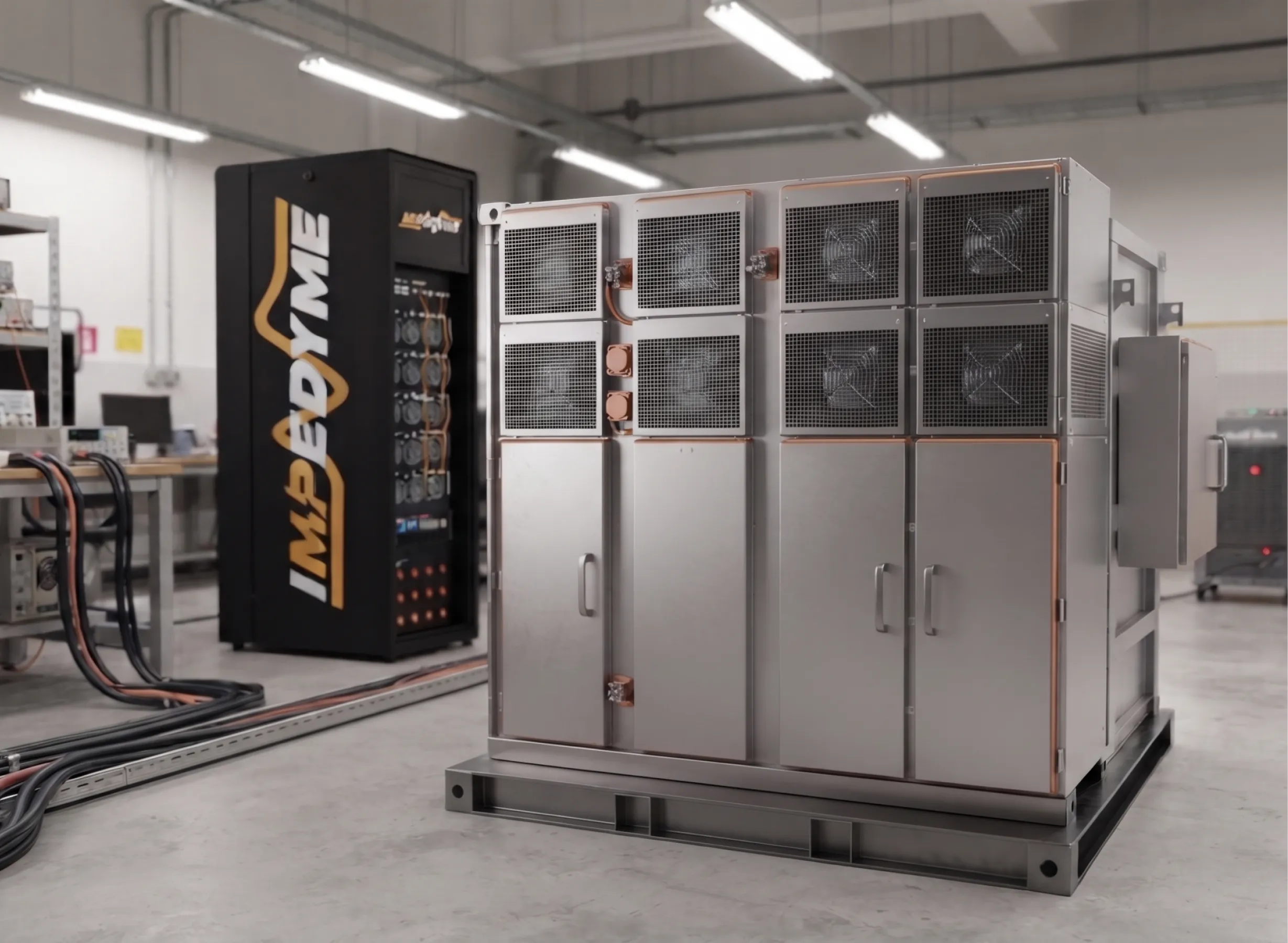
A packaged, field-grade solid state transformer looks less like a circuit board and more like a substation cabinet. The main sections of a medium-voltage SST enclosure are the following.

Fan and pump section (cooling)

Because an SST concentrates a lot of power into a small volume, thermal management is central. A cooling section houses fans, pumps, a coolant loop, and heat exchangers that carry heat away from the semiconductors and the medium-frequency transformer.

MV dead-front section and door

The medium-voltage compartment uses a dead-front design, meaning there are no exposed energized parts when the door is opened.It holds the MV terminations and bushings and is protected by interlocks so the equipment cannot be accessed while live.

LV dead-front section and door

The low-voltage compartment terminates the LV AC and/or DC output, again dead-front for operator safety, and houses the output-side protection and disconnects.

The tank

Analogous to a conventional transformer tank, this sealed section contains the medium-frequency magnetics and, in many designs, a dielectric coolant, providing insulation, heat transfer, and environmental protection for the most sensitive components.

Customer interface

The interface brings it together: input and output terminals, communications ports, monitoring, and an HMI/SCADA connection so operators can see and control the unit remotely.

Key Features of an SST Solid State Transformer

The features of an SST solid state transformer describe what the device can do that a passive unit cannot:

  • Bidirectional power flow for storage, vehicle-to-grid, and DER export
  • Active voltage regulation, holding output steady as input or load swings
  • Reactive power support
  • Harmonic filtering and power factor correction
  • Fault current limiting instead of a large uncontrolled fault contribution
  • Native DC ports (for example, an 800 V DC bus)
  • Built-in monitoring and communications
  • A compact, largely oil-free design compared with a conventional distribution transformer

Power Semiconductors for Solid State Transformers: MOSFETs, IGBTs, Diodes, Thyristors, and Gate Drivers

The switching devices are the heart of every solid state transformer. Medium-voltage silicon carbide (SiC) MOSFETs are the workhorse on the MV side and in the high-frequency stages, because they switch fast with low loss and block high voltage, which is exactly what keeps the magnetics small. Insulated-gate bipolar transistors (IGBTs) still appear in some designs, particularly at higher currents or where mature silicon is preferred. SiC Schottky and freewheeling diodes handle rectification and current recirculation. Thyristors can serve in protection, bypass, or crowbar roles, providing a rugged path to divert fault energy.

Tying them together are isolated gate drivers. In an SST they face brutal conditions — very high dv/dt, reinforced insulation requirements across medium voltage, and the need for fast short-circuit protection— so the gate driver is as much a reliability component as the switch it commands. In series-connected device strings, active gate drivers also help balance the voltage each device sees.

SST Control, Sensing, and Auxiliary Power Functions

A solid state transformer runs on a hierarchical control system: a central controller sets the overall targets while per-cell controllers manage each module. Microcontrollers and FPGAs execute the fast control loops, taking in isolated current and voltage measurements and issuing switching commands with tight timing. Fiber-optic links carry signals across the medium-voltage insulation boundary without creating a conductive path, and isolated auxiliary power supplies feed the gate drivers and control electronics safely. A communications layer exposes monitoring, setpoints, and protection status to the outside world — which is also why cybersecurity is now part of the control conversation.

Solid State Transformer vs Conventional Transformer

A solid state transformer and a conventional line-frequency transformer do the same basic job — change voltage and isolate — but almost everything else differs. The table below compares them across twelve attributes.

AttributeConventional line-frequency transformerSolid state transformer
Operating frequency50/60 HzTens of kilohertz internally
Magnetics size and weightLarge, heavy iron and copperSmall, light medium-frequency core
EfficiencyAbout 99% (AC-to-AC)About 97–98% device-level; system comparison shifts for DC loads
Voltage regulationPassive; taps onlyActive, continuous, fast
Power flow directionBidirectional but uncontrolledBidirectional and fully controlled
DC portsNoneNative DC output available
Power qualityNo active supportHarmonic filtering, power factor and reactive support
Fault currentLarge sustained contributionActively limited
InrushHighNegligible
Surge robustnessInherently ruggedMust be engineered in
Monitoring and communicationsMinimalBuilt-in
Field record and costCentury-long record, low first costEmerging record, higher first cost

An SST is not a drop-in replacement for every distribution transformer. It earns its place where control, DC output, or footprint matter more than the lowest AC-to-AC loss and the lowest first cost.

Types of Solid State Transformer Architecture: Single-Stage to Three-Stage

Solid state transformers are grouped by how many conversion stages they use and where their DC links sit.

Type & StagesDC Link & What It EnablesMain Trade-off
Single-stage — One (direct AC-AC)No DC link; simplest design with fewest partsNo DC port, limited control
Two-stage (MV DC link) — TwoMV DC link; enables greater controllability and MV DC accessNo LV DC port
Two-stage (LV DC link) — TwoLV DC link; enables an LV DC port and isolationNo MV DC bus
Three-stage (MV & LV DC links) — ThreeBoth DC links; full control and access to DC ports; most commonMost parts and complexity

Newer research proposes broader, multi-dimensional taxonomies of SST design, but the stage-and-DC-link view above covers the practical field.

Modular (multi-cell) vs single-cell designs

Modular approaches — input-series output-parallel cascaded cells and modular multilevel converters — stack many lower-voltage devices to reach medium voltage. This is scalable and fault-tolerant, but it means many parts and constant cell-voltage balancing. Single-cell designs lean on high-voltage SiC devices, using fewer parts but facing harder insulation and device limits.

Hybrid solid state transformer

A hybrid solid state transformer pairs a conventional transformer with a partially rated converter that processes only about 10–20% of the total power, reaching roughly 98.6% efficiency — close to a conventional unit — while the bulk of the load flows through the passive transformer. It is cheaper than a full SST and bulkier than one, and it is a sensible near-term fit for AC grids that mainly need voltage regulation and reactive support rather than a DC bus.

Solid State Transformer for Data Centers: Inside a 13.8 kV-to-800 V DC SST

The architecture tables above become much easier to picture with a concrete design. A representative solid state transformer for a hyperscale AI data center takes a 13.8 kV, 60 Hz three-phase feed and delivers a regulated 800 V DC bus straight to the GPU racks, with no 60 Hz transformer anywhere in the path. It uses the most popular modular topology for this job: a cascaded H-bridge (CHB) front end feeding dual active bridge (DAB) cells, an input-series, output-parallel arrangement.

The power path, step by step

  1. Input filter. The 13.8 kV grid connects through a series RL line filter that attenuates switching harmonics before they reach the utility.
  2. Cascaded H-bridge rectifier. Each of the three phases carries one CHB phase leg built from three series-connected H-bridge cells. Each cell rectifies its share of the phase voltage onto its own DC-link capacitor, at about 4.4 kV per cell. Stacking cells in series is what lets lower-rated semiconductors handle a medium-voltage line.
  3. Dual active bridge isolation. Every cell feeds its own DAB converter, so three phases times three cells gives nine DAB modules. Each DAB switches at around 20 kHz, provides galvanic isolation through its medium-frequency transformer, and steps the 4.4 kV cell voltage down to 800 V.
  4. Paralleled 800 V DC bus. All nine DAB outputs are tied together onto one common low-voltage DC bus that feeds the IT racks.

This is a two-stage, low-voltage-DC-link design in the terms of the architecture table: there is no separate inverter, because the load wants DC. That is exactly why a data center SST can replace three pieces of conventional equipment — the line-frequency transformer, the AC switchgear, and the rectifier — with one conversion chain.

Why the modular CHB-DAB layout suits data centers

  • Voltage sharing. Series cells divide the medium voltage across many lower-rated devices.
  • Redundancy. With a bypass path, a failed cell can be shorted out and the SST keeps running on the remaining cells (N+1 operation).
  • Scalability. Adding cells per phase raises the input voltage rating; adding DAB modules in parallel raises the output current.
  • Independent regulation. Each DAB has its own control authority, so the output bus can be held tightly even while the cells see slightly different conditions.

The control layers that make it work

A CHB-DAB SST is only as good as its controls. A typical design stacks five functions:

Control layerWhat it doesWhy it matters
Grid-side PFC controllerRuns a phase-locked loop and dq-frame current control; regulates every cell DC link to its setpoint while keeping reactive current at zeroUnity power factor across the whole load range, where a passive diode rectifier would drift badly at light load
DC voltage balancing (between phase legs)Adds a small per-phase correction to the modulation reference whenever one phase’s DC links drift away from the averageKeeps all three phase legs evenly charged even when the load is unbalanced
Central DAB voltage controllerOne controller compares the 800 V bus to its reference and sets a common phase shift for all DABs; the phase-shift range is capped below the point of maximum power transferHolds the DC bus tight and keeps the control loop on the stable side of the DAB’s power curve
DAB balancing trimAdds a deliberately small, slow per-phase trim to the phase shiftShares power evenly between phases without fighting the fast central loop
Supervisory logicHolds the DAB phase shift at zero during start-up until the cell DC links precharge; stops power transfer and resets the controller integrator during a deep AC voltage sag, with hysteresis to avoid chattering at the edge of the bandSafe start-up and clean behavior during grid faults

One practical lesson from modeling this topology: when every cell in a phase leg receives the same modulation command, balancing can only happen between phases, not between the individual cells of one leg. Designs that need cell-by-cell balancing must give each cell its own modulation offset — a detail worth settling early, because it changes both the controller architecture and the test plan.

How AI Workloads Stress a Data Center SST

A data center SST does not feed a steady, polite load. AI clusters swing their power demand hard and fast, and the SST sits between those swings and the utility grid.

Training and inference look very different

  • Training racks run bulk-synchronous cycles. Thousands of GPUs compute together near full power, then pause together to exchange data at close to idle power. A typical cycle repeats roughly every 800 milliseconds.
  • Inference racks follow request-driven prefill and decode cycles, so their demand is burstier and less periodic.
  • GPU power is not linear with utilization. Because of leakage and clock-distribution overhead, a GPU at half utilization can draw around 70% of its peak power, so even “light” operation keeps the SST heavily loaded.

Why the grid cares

When an entire training cluster switches between compute and communication in lockstep, the facility’s power draw oscillates at the training step rate. An 800 ms step creates a power swing near 1.25 Hz, with harmonics at about 2.5 Hz and 3.75 Hz. Those frequencies sit squarely in bands where power systems are sensitive:

Frequency bandGrid phenomenon at risk
Below 1 HzInter-area oscillations across the transmission network
1–2.5 HzCoupled oscillations between generators in the same or nearby plants
7 Hz and aboveTorsional resonances in turbine-generator shafts

At the scale of a single SST serving a few thousand GPUs, the swing is already measurable on the medium-voltage side. Scaled to a 100,000-GPU training cluster, it can reach hundreds of megawatts. Utilities also cap how fast a large load may ramp, so data center SST programs increasingly need to show ramp-rate compliance and, where limits are exceeded, a mitigation path such as GPU power smoothing, energy storage, or software load shaping.

What the SST must hold

Across these workloads, the core requirement is a steady DC bus. A common design target keeps the 800 V bus within ±5% (about 760–840 V) through load steps, load shedding, and unbalanced ramps, with emerging industry SST specifications calling for tighter dynamic regulation of around ±3%. Meeting that with the DAB controller alone, without leaning on backup energy, is the clearest sign the SST control is well tuned.

Rack-Level Battery Backup Behind a Solid State Transformer

Pairing each rack with a battery backup unit (BBU) gives the SST-fed DC bus a second line of defense. The most effective designs are hybrid: a supercapacitor for millisecond-range transients and a battery for events lasting seconds.

The two are coordinated with a complementary-filter approach:

  • Normal operation: a dead zone keeps both the supercapacitor and the battery completely silent. The SST’s DAB controller handles every ordinary load transient on its own.
  • Fault or islanding: once the bus voltage leaves the dead zone (or a fault flag bypasses it), a high-pass path sends the fast part of the voltage error to the supercapacitor for an immediate burst, while a low-pass path sends the sustained part to the battery controller.
  • No controller fighting: because the two paths split the error cleanly and only the battery controller carries steady-state authority, the two storage elements never work against each other.

This matters because server power supplies behave as constant-power loads: as bus voltage falls they draw more current, which can drive a weak bus toward collapse. The supercapacitor’s instant response stops that spiral, and the battery then carries the rack through the rest of the event. Rack-level BBUs also keep a local fault local. If a single rack’s DC breaker opens, that rack rides through on its own storage while the neighboring racks stay on the SST, undisturbed.

On the grid side, the same idea scales up: during a deep low-voltage event, a facility battery energy storage system can supplement power while grid voltage is too low for the SST to deliver full load, and the SST takes back over as voltage recovers.


SST Transformer and the Power Grid: Smart Distribution, Microgrids, and DER Integration

On the power grid, an SST transformer is more than a voltage changer — it is a controllable node. In smart distribution it provides fast voltage regulation and reactive power support, filters harmonics, and precisely controls power flow.Its bidirectional DC and AC ports make it a natural interface for distributed energy resources — solar, wind, and storage — improving a feeder’s hosting capacity for variable generation. In microgrids and hybrid AC/DC grids it can act as an energy router between subsystems,coordinating islanded and grid-connected operation. And because monitoring is built in, it doubles as a grid-edge sensor, giving operators visibility they never had from passive iron. These are the same dynamics we model in our work on power grid stability and grid-forming inverters.

Solid State Transformer Advantages and Limitations

Advantages

Solid state transformers pack a lot of capability into a small package. Their high-frequency operation makes the magnetics far smaller and lighter. They offer native DC ports, active voltage regulation, and power-quality services such as harmonic filtering, power factor correction, and reactive support. They support bidirectional flow for storage and vehicle-to-grid, isolate faults and limit fault current, and produce negligible inrush. Monitoring and communications are built in, and they use far less insulating oil than a conventional distribution transformer — a maintenance and environmental benefit.

Limitations and engineering challenges

The limitations are real and mostly economic and reliability-related. First cost is high, driven by SiC devices, medium-voltage packaging, and certification. There is an efficiency penalty in pure AC-to-AC service, where a conventional transformer’s roughly 99% is hard to beat. Field reliability under surges, heat, and years of medium-voltage stress is still being proven. Insulation and partial discharge in the medium-frequency transformer are demanding, as is managing dv/dt stress on devices and insulation. Modular designs require constant cell-voltage balancing. Because an SST limits rather than supplies large fault current, downstream protection coordination must be rethought — an SST simply cannot deliver the large, sustained fault current that conventional protective devices are set to detect. Cybersecurity becomes a design requirement once a transformer has firmware and communications. SiC device supply and immature standards round out the list.

Hype vs reality in 2026 The demand signals are genuine: DC-native data center architectures, acute transformer lead-time pressure, the first 22.9 kV-class designs announced at roughly 1 MVA, and medium-voltage products now scaling into the multi-megawatt range. But utility-wide replacement of distribution transformers is still years away. The near-term wins are DC-heavy sites — data centers and charging depots — not wholesale swaps of the passive fleet. Treat this section as time-sensitive and refresh it quarterly.

Standards and Certification for Solid State Transformers

There is no single published SST product standard yet. An IEEE recommended practice for the design and integration of solid state transformers in the electric grid, project IEEE P3105, is in development,and until it publishes, the ecosystem relies on a patchwork of existing standards that each touch part of an SST.

StandardWhat it coversWhere it touches an SST
IEEE 1547 / 1547.1DER interconnection and conformance testingWhere an SST interfaces or acts as a DER/storage interface
IEEE 519Harmonic limitsPower quality at the point of common coupling
IEEE C57 series / IEC 60076Conventional transformer requirementsReference for insulation, BIL, and temperature rise, though written for line-frequency magnetics
IEC 62477-1Safety of power electronic converter systemsThe converter hardware and its protection
IEC 61000 seriesElectromagnetic compatibilityEmissions and immunity
UL 1741Inverters/converters for DER (US)Grid-interactive functions and certification
IEC 61850Substation communicationsMonitoring and control integration
IEC 62443Industrial cybersecuritySecuring the SST’s controls and comms
IEC 60270Partial discharge measurementInsulation qualification of the MF transformer
IEC 61851-23 / UL 2202; IEC 61287-1DC EV charging; railway traction convertersApplication-specific SST use cases

The in-development IEEE P3105 recommended practice aims to knit these threads together and map legacy transformer tests onto the SST’s medium-frequency magnetics, but until it is published, every SST program stitches its own compliance path from the pieces above.

How Solid State Transformers Are Validated Before Grid Connection

Here the validation gap comes into sharp focus: the hardware is moving faster than the standards, so every SST team writes its own test plan — and the first time firmware meets a medium-voltage fault should never be on energized hardware.

The validation path runs as a short, staged sequence:

  1. Offline model — simulate the converter and grid to prove the concept.
  2. Controller HIL — the real controller runs against an FPGA real-time model of the full multi-cell SST and the grid.
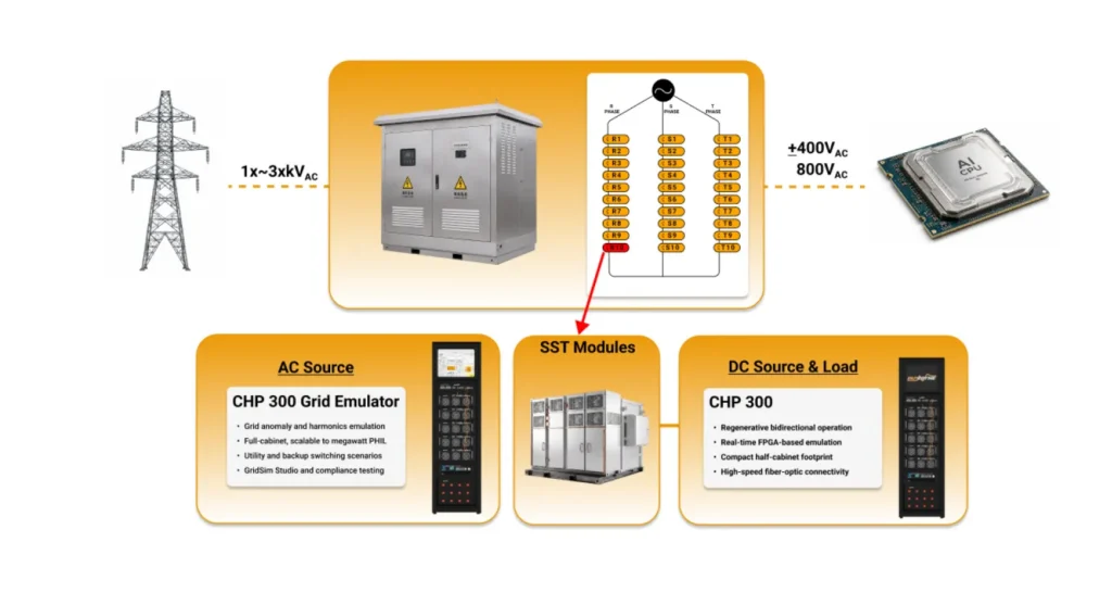
  3. Power HIL — the real power stage runs against a grid emulator and a DC source/load, at cell/module level and at the SST’s low-voltage AC/DC ports.
  4. Type and certification tests — the medium-voltage, full-power qualification on the complete unit.

Across these stages the plan exercises start-up and precharge, cell-voltage balancing, load steps, grid faults and ride-through, device and sensor fault injection, harmonics, grid-forming and islanding transitions, and communications loss.

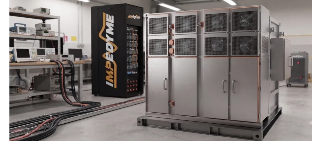
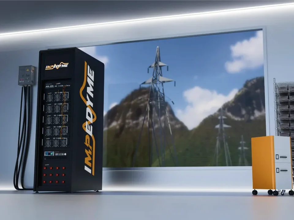
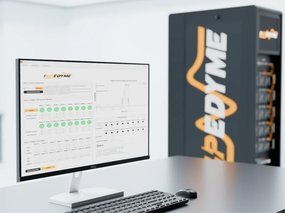
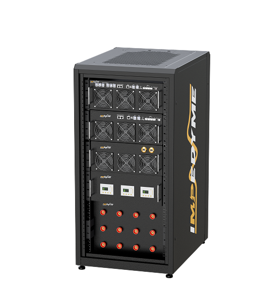
At Impedyme, we focus on the pre-energization stages that take the risk out before medium-voltage type testing — we do not claim to energize or type-test a complete medium-voltage SST at full rated voltage and power. Our CHP Series combines controller HIL and full-power PHIL in one FPGA-based, regenerative platform, available in CHP-150 and CHP 300 configurations and scalable by paralleling. GridSim Studio turns the CHP Series into a programmable grid emulator that models source impedance, feeders, faults, and compliance profiles rather than replaying a fixed stimulus. PowerHIL Studio orchestrates automated test sequences, fault campaigns, and pass/fail reporting, FPGA Scope captures waveforms at model resolution, with model updates as fast as 90 nanoseconds on our FPGA-based platform.A CHP cabinet delivers up to 50 kW of Power-HIL, scaling to 550 kVA/kW paralleled, with megawatt-scale power HIL available for larger programs. This is the de-risking layer: run the real controller against a real-time model of the full SST and grid, then bring real power to the cell and to the LV ports, long before the first medium-voltage energization. For the full scenario matrix and product mapping, see our dedicated article. Related work includes our inverter test and power shelf testing resources.

Conclusion: Where the Solid State Transformer Fits Next

The solid state transformer is no longer a purely academic idea. In 2026 it is the enabling device for 800 V DC data centers, megawatt EV charging, and DC-native renewables and storage, and it is beginning to prove itself on real distribution feeders. It is not a universal replacement for the passive distribution transformer — a conventional unit still wins on pure AC-to-AC efficiency and first cost — but where controllability, DC output, power quality, and footprint matter, the SST is compelling. The gating factor is no longer whether the hardware works; it is whether teams can validate control and protection thoroughly and safely before energization. That is exactly why solid state transformers, and the SST transformer programs building them, should treat staged HIL and power-HIL validation as the bridge across the validation gap — proving what a solid state transformer will do on the grid before it ever touches medium voltage.

Frequently Asked Questions 

Is a solid state transformer more efficient than a conventional transformer?

Not universally. A conventional transformer reaches about 99% AC-to-AC, while an SST is typically about 97–98% at device level. But when an SST replaces a transformer plus a rectifier for DC loads, the system comparison shifts, because the conventional AC-to-DC chain also loses efficiency in its separate rectifier.

Why do data centers want solid state transformers?

AI compute is pushing data centers toward 800 V DC distribution. An SST converts a medium-voltage AC feed directly to a regulated DC bus, removing conversion stages, cutting copper because higher voltage means lower current, and easing transformer lead-time pressure that delays speed to power.

What are the main limitations of solid state transformers?

High first cost, a small efficiency penalty in pure AC service, unproven long-term field reliability under surges and heat, demanding insulation and partial-discharge control, dv/dt stress, cell-voltage balancing, the need to rethink protection coordination because fault current is limited, cybersecurity, constrained SiC supply, and immature standards.

Does a solid state transformer still contain a transformer?

Yes. An SST contains a medium-frequency transformer that provides galvanic isolation and the voltage ratio. “Solid state” refers to the power electronics replacing the bulky line-frequency magnetics, not to the absence of a transformer altogether.

How are solid state transformers tested before grid connection?

Through a staged path: offline modeling, controller hardware-in-the-loop against a real-time model of the full SST and grid, power hardware-in-the-loop at cell level and the LV ports against a grid emulator and DC source/load, and finally medium-voltage type and certification testing on the complete unit.