SRM Control Techniques: Flux Linkage, Voltage, Current, and Torque
Every switched reluctance motor controller works on one chain of cause and effect. The converter applies voltage. Voltage, minus the resistive drop, builds up over time into flux linkage. Flux linkage and rotor position together fix current, and current and position together fix torque. The phase voltage balance includes a motional back-EMF that grows with speed and with current. That back-EMF explains most of the high-speed behavior of a switched reluctance motor.
Techniques are grouped by the variable they control:
- Voltage control: fixed-duty or commanded PWM sets the average phase voltage.
- Current control: current chopping regulates phase current to a reference.
- Flux-linkage control: the drive tracks a flux reference for each phase.
- Torque control: torque-sharing functions split the torque demand between the outgoing and incoming phases. Direct instantaneous torque control and SRM-specific direct torque control act on estimated torque directly.
- Angle position control: at high speed, the turn-on and turn-off angles themselves become the control variables.
An outer speed loop usually supplies the torque or current demand. Terminology varies between sources. In this article, each term means what is defined here.
Position Sensing and Sensorless SRM Control
Sensor options for an SRM motor include optical or magnetic encoders, resolvers, and a slotted disc read by Hall or optical sensors. A slotted disc is often enough for commutation alone. Angle error shifts both turn-on and turn-off, which reduces torque and efficiency and increases ripple and noise, so position accuracy directly affects drive quality.
Sensorless families include:
- Flux-linkage or current lookup against stored flux-linkage maps.
- Incremental-inductance estimation.
- Diagnostic pulse injection into idle phases.
- Observer-based methods.
Standstill and low speed are the hardest regions, because there is little motional back-EMF to observe and short voltage pulses must be injected into idle phases. Observers and flux methods work better at medium and high speed, so the drive must hand over smoothly from one method to another. Saturation, temperature and mutual coupling all make estimators sensitive to parameter changes. Every sensorless switched reluctance drive needs a defined, safe start-up procedure, including a rule for what happens if the initial position estimate is wrong.
SRM Modulation Techniques: Voltage Chopping and Control Chopping
It helps to separate the switching pattern from the variable being controlled.
Voltage chopping applies a fixed or commanded PWM duty during the conduction interval, which sets the average phase voltage. Current is not directly regulated, so this suits low-cost drives and soft-start.
Control chopping, treated here as current chopping control (CCC), regulates phase current in closed loop to a reference, either by hysteresis (variable frequency) or by fixed-frequency PWM.
In a reluctance motor drive, the asymmetric half wave rectifier gives each phase three voltage states:
- Positive DC-link voltage: both switches on, and current builds.
- Zero voltage: one switch on, with current freewheeling through one diode.
- Negative DC-link voltage: both switches off, and current returns through both diodes to the DC link.
Soft chopping alternates between positive and zero voltage. Hard chopping alternates between positive and negative voltage.
| Property | Soft chopping | Hard chopping |
| Current ripple at a given frequency | Lower | Higher |
| Switching loss | Lower (one device switches) | Higher (both devices switch) |
| DC-link ripple current | Lower | Higher (energy shuttles to and from the link each cycle) |
| Acoustic excitation | Generally lower | Generally higher |
| Demagnetization speed when needed | Slow if limited to zero voltage | Fast |
Single-Pulse Operation and the Switched Reluctance Motor Torque-Speed Envelope
As a switched reluctance motor speeds up, motional back-EMF approaches the DC-link voltage. Current can no longer reach the chopping band, and the drive moves to single-pulse operation: one voltage pulse per stroke, with control only through the turn-on and turn-off angles. To hold torque, the switched reluctance motor controller advances turn-on so that current builds while inductance is low, and widens the dwell, while still ensuring flux decays before the falling-inductance region.
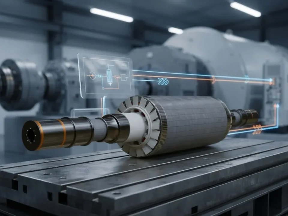
Conceptually, the torque-speed envelope of an SRM motor has three regions. Below base speed is a current-limited constant-torque region. Above it is an angle-controlled region of roughly constant power. Beyond that is a falling “natural” region. Where these boundaries fall depends on the design, and they are not universal.
Reducing Torque Ripple, Vibration, and Acoustic Noise
Many explanations of the reluctance motor merge two separate problems:
- Torque ripple is a tangential pulsation caused by discrete strokes and dips at commutation.
- Acoustic noise comes mainly from radial force pulsation that excites the stator’s ovalizing modes. It is especially strong when current, and therefore radial force, drops abruptly at turn-off.
Mitigations fall into three groups:
- Control: phase overlap; torque-sharing functions; current profiling with flux-linkage or torque maps; angle optimization; two-step or staged turn-off that steps voltage down through a zero-voltage interval.
- Modulation: switching-frequency choice to avoid structural resonances, and randomized PWM.
- Machine design: pole shaping, phase count, a stiffer yoke, and air-gap and frame design.
None of this is free in a switched reluctance drive. Profiling and overlap raise peak and RMS current, copper loss, current-loop bandwidth requirements and computing load.
Switched Reluctance Motor vs Other Motor Types
| Criterion | Switched reluctance | Other motor types |
| Rotor construction | Salient laminated steel | Brushed DC: wound armature and commutator · Induction: cage bars in laminations · PM/BLDC: magnets on or in rotor · SynRM: flux-barrier laminations · VR stepper: toothed steel |
| Magnets | None | Brushed DC: stator magnets or field winding · PM/BLDC: yes · Induction, SynRM (unless PM-assisted) and VR stepper: none |
| Rotor conductors | None | Brushed DC and induction: yes · PM/BLDC, SynRM and VR stepper: none |
| Converter | SRM-specific, unipolar | Brushed DC: DC chopper or H-bridge · Induction, PM/BLDC and SynRM: standard inverter · VR stepper: stepper driver |
| Commutation | Electronic, position-synchronized | Brushed DC: mechanical · Induction: none needed · PM/BLDC: electronic · SynRM: electronic (vector control) · VR stepper: open-loop steps |
| Current waveform | Unipolar pulses | Brushed DC: DC · Induction and SynRM: sinusoidal · PM/BLDC: sinusoidal or trapezoidal · VR stepper: pulsed |
| Torque density | Application-dependent | PM/BLDC: high · Brushed DC, induction and SynRM: moderate · VR stepper: low to moderate |
| Ripple and noise | High unless mitigated | Induction and PM/BLDC: low · SynRM: low to moderate · Brushed DC: moderate (brush noise) · VR stepper: high at resonance |
| Fault behavior | Phases isolated; no magnet back-EMF into a shorted phase | PM/BLDC: magnets keep driving current into a shorted winding while spinning · SynRM: no magnet-induced back-EMF · Induction: robust · Brushed DC: brush and commutator wear · VR stepper: loses steps |
| Temperature and speed suitability | Very good (rotor-limited by stress) | Induction and SynRM: good · PM/BLDC: limited by magnet temperature and retention · Brushed DC: limited by brushes · VR stepper: low speed |
| Control complexity | High (nonlinear) | Brushed DC and VR stepper: low · Induction, PM/BLDC and SynRM: moderate |
Switched reluctance and synchronous reluctance are often confused. The switched reluctance motor is doubly salient, uses concentrated coils and runs on pulsed unipolar current. The synchronous reluctance motor has a distributed stator winding like an induction machine and a flux-barrier rotor, and runs on sinusoidal current from a standard inverter. The comparison above is qualitative. Quantitative claims need measured data from comparable machines.
Power Electronics and SRM Converter Topologies
Every SRM phase needs three things from its converter, all at unipolar current: magnetization (positive voltage), freewheeling (zero voltage) and fast demagnetization (negative voltage). The asymmetric half-bridge is the reference topology. It uses two switches and two diodes per phase, with the winding connected between them. With both switches on, current flows from the positive rail through the winding to the negative rail. With one switch on, current circulates through the winding, that switch and one diode. With both switches off, the winding forces current through both diodes back into the DC link. The stored magnetic energy returns to the DC-link capacitor, and the capacitor must absorb that pulsating energy.
| Topology | Circuit and voltage behavior | Regeneration, stress and faults |
| Asymmetric half-bridge | 2 switches + 2 diodes per phase · Full phase independence · Positive, zero and negative voltage · Demagnetizes at full DC link | Regenerates: yes · Device stress: DC link · Good fault behavior; a failed leg affects one phase |
| Shared-switch (one per phase plus a common switch) | Fewer switches · Independence limited during overlap · Restricted voltage states · Demagnetizes at full DC link | Regenerates: yes · Device stress: DC link · Common switch is a single point of failure |
| Split DC link (even phase counts) | 1 switch + 1 diode per phase · Partial independence · Positive and negative half-link · Demagnetizes at half DC link | Regenerates: yes · Device stress: full DC link · Needs capacitor voltage balancing |
| C-dump | 1 switch per phase + dump circuit · Good independence · Positive and negative voltage · Demagnetization voltage set by dump capacitor | Regenerates via recovery chopper · Device stress: elevated · Dump circuit adds failure modes |
| Bifilar winding | 1 switch + 1 diode per phase · Good independence · Positive and negative voltage · Demagnetizes through secondary winding | Regenerates: yes · Device stress: above DC link (leakage spikes) · Extra copper; imperfect coupling |
| R-dump | 1 switch per phase + resistor · Good independence · Positive voltage, slow decay · Low demagnetization voltage | No regeneration (energy dissipated) · Device stress: moderate · Simple, but inefficient |
No topology is universally best. The asymmetric half-bridge dominates performance applications because each phase is fully independent. Reduced-switch topologies trade that independence for cost.
Advantages and Limitations of Switched Reluctance Motors
Advantages
A switched reluctance motor offers several system-level benefits:
- Magnet-free rotor, with no exposure to rare-earth supply.
- Robust rotor suited to high speed and high temperature.
- Low rotor loss, with heat produced mainly in the stator, where it is easy to cool.
- Electrically isolated phases, allowing continued operation with a failed phase in suitable topologies.
- Simple, low-cost manufacturing.
Limitations
The same simple reluctance machine also brings trade-offs:
- Torque ripple and acoustic noise.
- Need for position information.
- Nonlinear control.
- An SRM-specific converter.
- High DC-link ripple current.
- Tight air-gap tolerances.
- Torque density that depends on the application.
Wider adoption of the SRM motor depends on the drive, not the machine. Faster semiconductors, more capable embedded processors, better electromagnetic and system simulation, and acoustic-aware control strategies are all reducing the cost of handling its nonlinearity in the switched reluctance motor controller. Those same tools also make thorough validation more practical.
Can a Switched Reluctance Motor Work as a Generator?
Yes. To generate, the switched reluctance motor controller excites a phase near alignment and keeps current flowing while inductance falls. Mechanical work done by the prime mover then increases the energy in the magnetic field. The current returned at turn-off carries more energy than the excitation supplied, so net power flows into the DC link.
A switched reluctance generator does not self-excite in the way a magnet machine does. It needs a charged DC link or another source, plus controlled excitation every stroke. That is a safety advantage: removing excitation stops generation, even into a shorted winding.
Generator uses for this reluctance machine include regenerative braking in SRM traction drives, aircraft and engine starter-generators, flywheel energy storage, and wind and wave energy research, including linear machines. Aircraft starter-generators have been built and tested at the hundreds-of-kilowatt scale, while wind and wave uses are largely at the research stage.
Switched Reluctance Motor Applications
| Sector | Example uses | SRM property that motivates it | Main concern |
| Automotive | EV and hybrid traction, power steering, cooling pumps, electric boosting | Magnet-free rotor, high speed, fault tolerance | Noise and ripple in the cabin; torque density |
| Aerospace | Starter-generators, fuel pumps, actuators | High temperature, high speed, fault tolerance | Mass, containment, certification |
| Industrial | Pumps, fans, compressors, conveyors, crushers, extruders | Robustness, wide speed range, high starting torque | Drive cost against standard inverter-fed induction motors |
| Mining and construction vehicles | Shearers, haulage and conveyor drives, hybrid drives in underground loaders | Ruggedness, high torque at low speed | Hazardous-area compliance |
| Appliances | Vacuum cleaners, washing machines | Very high speed, low-cost rotor | Acoustic quality |
| Machine tools | Spindles | High speed | Ripple at the cutting edge |
| Energy | Flywheels, renewable generators | Robust rotor, controllable excitation | Efficiency at partial load |
| Transport research | Linear SRMs for rail and maglev | No magnets on the long track side | Force ripple, cost of the track |
Appliances, some industrial drives and mining equipment have the clearest history of commercial deployment. Direct-drive washing machines with SR motors reached the market in the late 1990s, and SR motors running at around 100,000 rpm have been sold in vacuum cleaners since the mid-2000s. SR drives have also been supplied for conveyors, traction systems and pumps in mining. Traction, aerospace and renewable uses include production programs, demonstrators and a large body of research. Brushless construction alone does not establish hazardous-area or explosion-protection compliance. That requires certification of the complete machine and drive.
Testing and Validating an SRM Drive
A staged path builds confidence before hardware is put at risk. Each stage proves something specific and leaves something unproven.
- FEA and system simulation. Compute flux-linkage and torque maps against angle and current, then simulate the drive. Proves: concept, envelope, first-cut losses. Cannot prove: manufacturing tolerances, real sensor behavior, firmware timing.
- Static characterization. Lock the rotor of the SRM motor at indexed angles, apply voltage pulses to one phase, and derive flux linkage against current from the measured phase voltage and current. Measure static torque with a transducer. Proves: the real magnetic maps. Cannot prove: dynamic or thermal behavior.
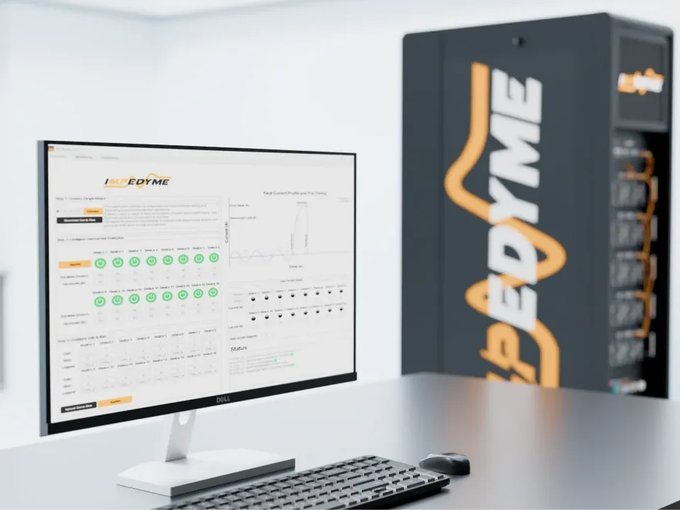
- Controller-Hardware in the Loop . Run the production switched reluctance motor controller against a real-time machine and converter model at signal level. Impedyme’s CHP Series and HIL/RCP Box real-time targets support this stage. FPGA Scope captures internal signals at sub-microsecond resolution, and PowerHIL Studio orchestrates automated test sequences. Proves: commutation logic, current loops, sensorless start-up, protections, fault reactions. Cannot prove: power-stage behavior.
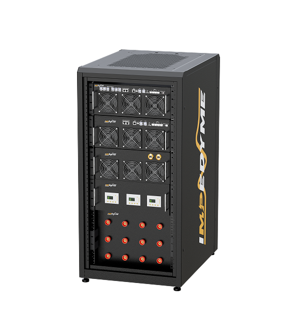
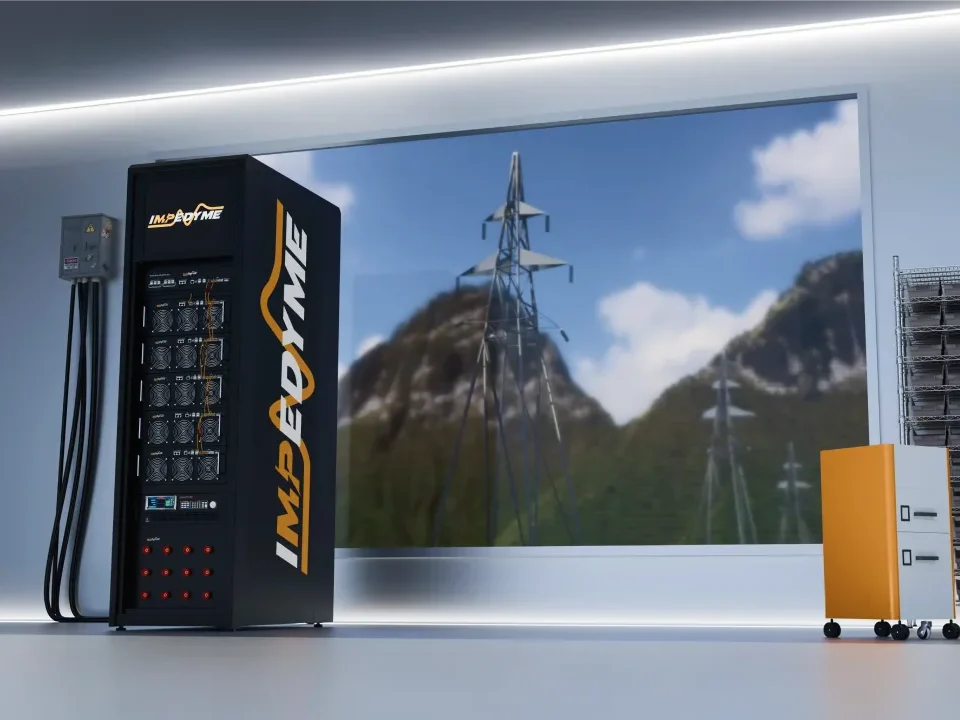
- Power-HIL (Power Hardware in the Loop). The real converter and controller drive a motor emulator that must reproduce: nonlinear, saturating flux linkage against angle; unipolar pulsed current with fast current rise and fall; energy returned during demagnetization; mutual coupling where relevant; position-sensor outputs; and mechanical dynamics. An Impedyme motor emulator, configured through MotorSim Studio, can support this stage with angle-dependent flux and torque maps and programmable fault injection (open phases, phase shorts, sensor faults). Confirm SRM model availability with Impedyme engineering before planning around it. Proves: the converter and controller together at real voltage and current, including faults that would damage a real machine. Cannot prove: acoustics, true thermal behavior of the machine, or mechanical resonances.
- Dynamometer testing. Measure efficiency maps, thermal limits, overspeed, vibration and acoustics of the reluctance motor and its drive. Relevant references include IEC 60034-1 for ratings, IEC 60034-2-3 methods for converter-fed motor losses (written for AC motors, so check applicability), IEC 61800 parts for adjustable-speed power drive systems, and ISO 3744 for sound power determination.
SRM drive test matrix
| Test case | Test stages | Key pass criteria |
| Voltage chopping, full speed range | Controller-HIL, P-HIL, dynamometer | Stable speed loop, current within limits |
| Current chopping (soft and hard) | Controller-HIL, P-HIL, dynamometer | Current tracking, DC-link ripple, switching loss |
| Single-pulse, high speed | Controller-HIL, P-HIL, dynamometer | Torque held through angle control, no negative-torque tail |
| Sensorless start from standstill | Controller-HIL, P-HIL, dynamometer | Correct direction from all initial positions |
| Angle error injection | Controller-HIL, P-HIL | Graceful degradation of torque and ripple |
| Open phase | Controller-HIL, P-HIL, dynamometer (limited) | Continued operation at reduced torque, correct alarms |
| Switch short or open fault | Controller-HIL, P-HIL | Safe shutdown or isolation, no DC-link overvoltage |
Conclusion
The switched reluctance motor’s simple, magnet-free rotor moves the complexity into the converter, the sensing and the switched reluctance motor controller. The inductance profile and the commutation angles connect all of it: torque, losses, noise and the speed envelope. An SRM motor fits best where magnet-free robustness, high speed or high temperature, or fault tolerance matter more than torque ripple, acoustic noise and drive cost, which sets it apart from other reluctance motor types in the reluctance machine family. The practical next step for any switched reluctance project is to characterize the flux-linkage and torque maps of this reluctance electric motor, then validate the converter and control, including faults, in controller-HIL and power-HIL before committing to full dynamometer testing.