
electric aircraft hil testing header card

Application knowledgeGridMotorProduct knowledgeWebinars

electric aircraft hil testing header

Electric Aircraft HIL Testing

The global aerospace sector is experiencing its most profound structural transformation since the transition from piston engines to gas turbines. This transformation is driven by two powerful industrial trends: the rapid rise of electrified powertrains and the exponential increase in systemic connectivity across aircraft architectures . To meet stringent global sustainability mandates and lower carbon footprints, development organizations are aggressively researching advanced energy storage systems, distributed electric propulsion, and highly efficient power-conversion processes .

In this new era, conventional mechanical, hydraulic, and pneumatic systems are systematically being replaced by high-power electrical equivalents. This technological shift has yielded two primary civil aviation concepts: More Electric Aircraft (MEA) and all-electric Vertical Take-Off and Landing (eVTOL) aircraft. While MEA architectures optimize secondary power systems by relying on a centralized electrical microgrid, eVTOL systems rely entirely on electric propulsion for lift, thrust, and control.

However, translating these conceptual vehicle designs into commercially viable, certified aircraft presents unprecedented engineering and validation challenges . Unlike automotive applications, aerospace systems operate under safety-critical margins where single-point failures can lead to catastrophic hull loss. Consequently, civil aviation authorities, such as the Federal Aviation Administration (FAA) and the European Union Agency for Safety (EASA), enforce rigorous compliance frameworks before any novel technology can be certified for flight.

Because traditional development and physical testing methods are slow, hazardous, and prohibitively expensive, the aviation industry has turned to a validation paradigm centered on Aerospace Hardware-in-the-Loop Simulation. This technique integrates high-fidelity real-time simulation with actual physical control hardware, enabling comprehensive, automated, and safe testing under every conceivable operational and environmental condition. Through advanced combined Hardware-in-the-Loop (HIL) and Power Hardware-in-the-Loop (PHIL) validation platforms, aerospace organizations can de-risk complex architectures, accelerate flight certification, and reduce time-to-market.

Why Electric Aircraft Testing Is Changing

Three forces are reshaping how aircraft are built and tested. First, powertrains are electrifying: distributed electric propulsion, high-voltage battery packs, and power-dense inverters now sit at the heart of the aircraft, not at its periphery. Second, integration complexity is exploding — every kilowatt of power conversion adds control loops, communication buses, and failure modes that interact. Third, sustainability is driving an entirely new class of air mobility vehicles, from eVTOL air taxis to hybrid-electric regional aircraft.

Traditional aircraft ran on 115 V AC (400 Hz) and 28 V DC power systems. More electric aircraft are transitioning toward high-voltage DC — 270 V and 540 V today, with 800 V and beyond being explored for megawatt-class propulsion — because higher voltage means lower current, lighter wiring, and less weight. eVTOL traction packs commonly run at 400 V and 800 V architectures, and some designs push battery voltages much higher. 

This electrification lands squarely in safety-critical territory. A flight controller that mismanages a motor drive, a BMS that misreads a cell, or an inverter that mishandles a fault can end a flight. That raises the stakes for testing and certification, which must be faster, more thorough, and more reliable than ever.

What Is Electric Aircraft HIL Testing?

Hardware-in-the-Loop testing replaces a physical system with a real-time digital simulation while keeping the controller hardware real. For an eVTOL, that means a real motor controller unit, a real BMS controller, or a real flight-control computer runs against a real-time test system that behaves like a digital twin of the plant — the motors, inverters, battery cells, sensors, and buses it would see in flight.

The controller cannot tell the difference. It reads sensor signals, issues commands, and closes its control loops exactly as it would on the aircraft — except the “aircraft” is a deterministic simulation running on FPGA-based real-time hardware. This unlocks a class of testing that is impossible or unsafe on real iron:

  • Closed-loop testing: the controller and the emulated plant interact continuously in real time, not against a static recording.
  • Dynamic scenarios: drive cycles, flight profiles, transitions, and disturbances can be scripted and replayed.
  • Full test automation: entire campaigns run unattended, generating automated reports and test evidence.
  • Requirements-based testing: each test links back to a system requirement, supporting certification traceability.
  • Regression testing: every firmware revision can be re-run against the same scenario library with perfect repeatability.

HIL versus data-acquisition (open-loop) testing

Many teams still rely on data-acquisition or open-loop bench testing, where signals are recorded and analyzed but the device under test is not driven by a live, reactive model. The difference is decisive for safety-critical aerospace controllers.

DimensionData-Acquisition / Open-Loop TestingElectric Aircraft HIL Testing
LoopOpen loop — records or plays back signalsClosed loop — controller and plant react to each other in real time
Fault scenariosHard or dangerous to stage physicallyScripted, safe, and repeatable (short circuit, broken wire, over-voltage)
Dynamic behaviorLimited to captured conditionsFull dynamic drive cycles, transitions, and disturbances
AutomationOften manualFull campaign automation with auto-generated reports
Certification evidenceFragmentedRequirements-based, traceable, regression-ready
CoverageNarrowBroad — thousands of scenarios including edge cases
RepeatabilityVariableDeterministic and identical across runs

This is the heart of Impedyme’s validation-gap narrative: offline simulation is fast but not real; full flight hardware is real but slow, costly, and dangerous to push to its limits. FPGA-based HIL and PHIL sit precisely in the middle — real controllers, real signals, and (in PHIL) real power, against a high-fidelity model that can be driven anywhere the requirements demand.

aerospace hardware in the loop

From Data Acquisition to Closed-Loop Real-Time Simulation

To appreciate the necessity of HIL testing, one must distinguish between open-loop data acquisition and closed-loop real-time simulation.

In data-driven, open-loop testing, engineers record physical sensor signals, apply post-processing scripts, and play back these predefined stimuli to a controller under test. While useful for component calibration and basic software debugging, open-loop testing fails to replicate dynamic systems. Because the controller’s outputs are not connected to a live model, the simulated environment does not adapt to the controller’s decisions.

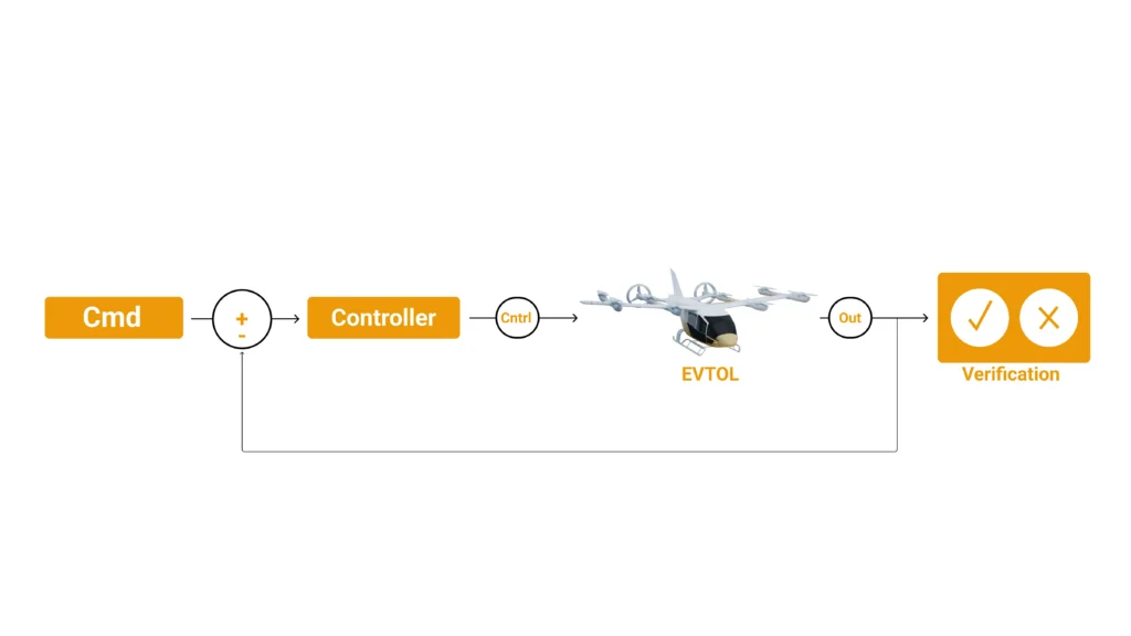
In contrast, Aerospace Hardware-in-the-Loop Simulation operates in a closed loop. The physical controller under test is connected to a real-time simulator running a dynamic digital twin of the plant (e.g., the aircraft’s aerodynamics, motor, or battery). The simulator captures the controller’s command outputs (such as gate-driver signals or throttle commands), calculates the state of the plant in real time, and immediately updates the emulated sensor feedbacks fed back to the controller’s inputs. This continuous loop executes with deterministic latency, enabling the testing of complex dynamic maneuvers, transient stability, and fault recovery.

Open-Loop DAQController HIL (CHIL)Power HIL (PHIL)
Connection: Open-loop; record and play backConnection: Closed-loop; real-time physical logic interfaceConnection: Closed-loop; real-time physical power interface
Power Level: Low signal level (milliwatts)Power Level: Low signal level (milliwatts to millivolts)Power Level: High power (kilowatts to megawatts)
Verifies: Sensor calibration, basic signal logging, offline diagnosticsVerifies: Software logic, state machines, communication protocols, safety limitsVerifies: Power quality, thermal behaviors, hardware efficiency, protection devices
Safety Risk: Negligible; no closed-loop interaction or high powerSafety Risk: Low; isolated from high voltages and currentsSafety Risk: Moderate to High; involves real voltage and current

The Physics of Temporal Resolution in Real-Time Emulation

In power electronics testing, the fidelity of the simulation is highly sensitive to the temporal resolution (the simulation time step) of the real-time execution engine. Modern aviation inverters utilize high-speed switching devices based on Silicon Carbide (SiC) or Gallium Nitride (GaN) technologies, which switch at frequencies ranging from tens to hundreds of kilohertz.

If the simulation time step is too large (e.g., 20 microseconds to 50 microseconds, typical of standard CPU-based simulators), the simulator cannot accurately resolve the exact moment the Pulse-Width Modulation (PWM) gate-driver signal switches from high to low. This timing mismatch introduces artificial quantization errors—frequently referred to as PWM duty-cycle errors—which can distort simulated current waveforms by up to 20%.

To suppress these errors to less than 1%, the simulator must operate with sub-microsecond time steps. Capturing high-frequency switching dynamics requires a platform that combines high-speed digital input capture with ultra-low latency FPGA-based execution. By executing the power converter and electric motor models directly on an FPGA, the simulation can run at time steps below 1 microsecond, capturing nanosecond-level switching edges and ensuring realistic inverter and motor control validation. Impedyme’s FPGA-based HIL testing eliminates these bottlenecks by integrating processing and I/O on the same chip, achieving simulation steps as fast as 1 microsecond and enabling true real-time simulation of switching devices.

Model-Based Design and Requirements Traceability

Certifiable electric aircraft software and hardware cannot be tested into compliance after the fact. The discipline starts with model-based design and requirements traceability, and HIL is where that traceability is proven.

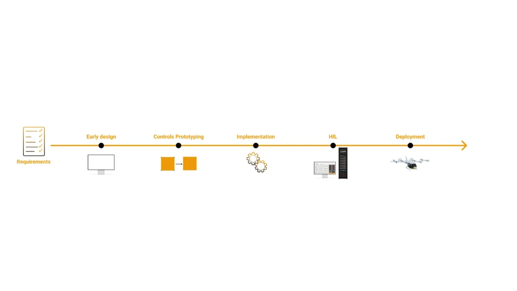
A robust workflow runs like this:

  • Requirements definition: capture high-level and low-level requirements for the controller and system.
  • Requirements traceability: import requirements from various sources using a requirements interchange format, then link each requirement to architecture, design, test cases, and implementation code.
  • Coverage analysis: confirm every requirement is exercised by at least one test and every piece of code traces to a requirement.
  • Change synchronization: when a requirement changes, propagate it through design, code, and tests automatically.
  • Report generation: produce the traceability matrices and test evidence certification authorities expect.

PowerHIL Studio anchors the verification end of this chain. Its scenario and sequence editor builds automated test campaigns; each test maps to a requirement; pass/fail criteria and key metrics (current ripple, torque ripple, efficiency, protection response) are logged; and reports are generated automatically as test evidence. Run the same suite after every firmware change, and you have regression evidence that satisfies requirements-based testing objectives.

Inside an FPGA-Based Electric Aircraft HIL System

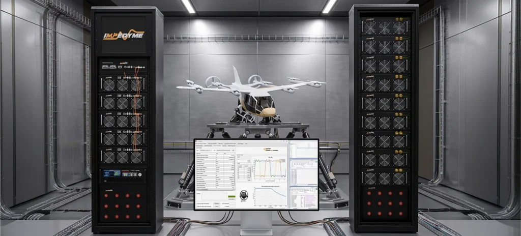
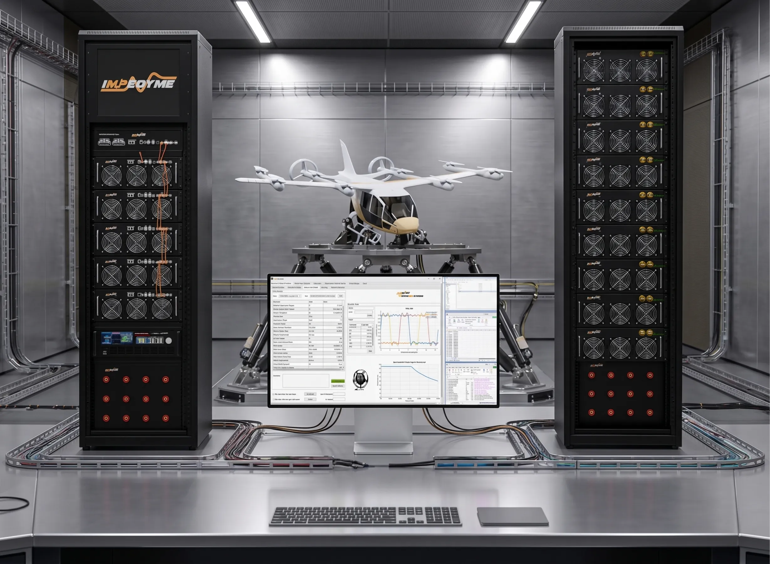
A complete electric aircraft HIL system has three parts.

  1. The system under test. This is the real, production-intent hardware: the motor controller unit, domain controllers, the BMS controller and its cell monitoring units, plus real sensors and actuators where relevant.
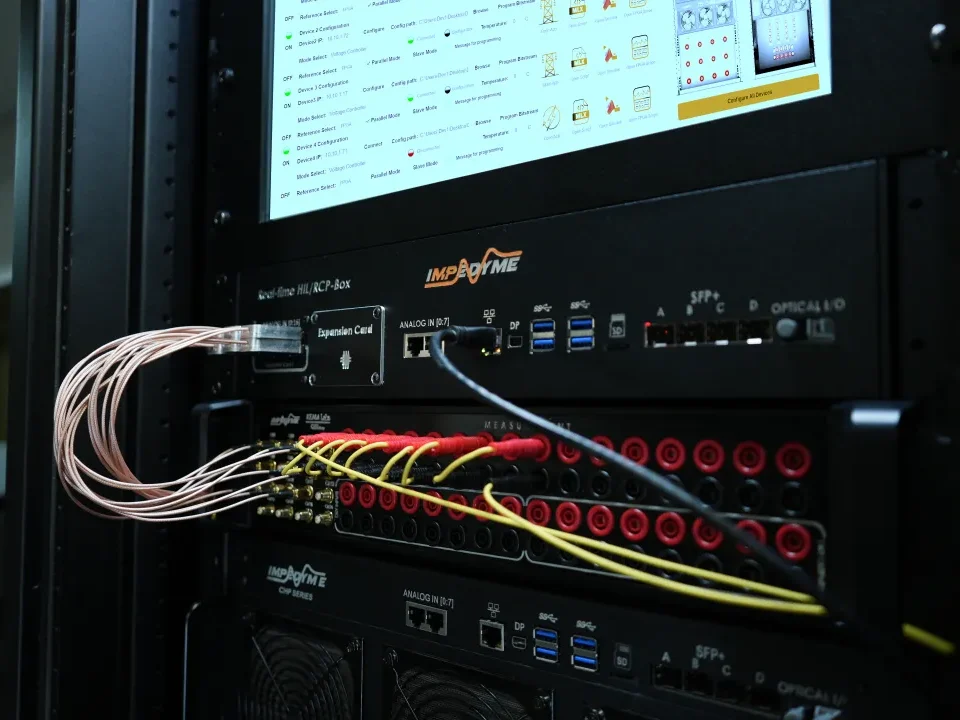
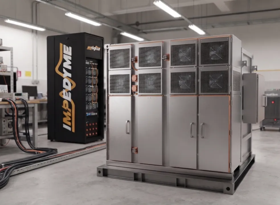
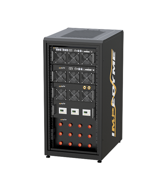
  2. The HIL test bench. This is the FPGA-based real-time simulator running the digital twin of the plant, together with emulated plant components (motors, inverters, battery cells), I/O modules for data acquisition, signal conditioning, and communication interfaces (CAN, ARINC 429). This is where Impedyme’s CHP Series lives.
  3. The workstation. This runs the application software — PowerHIL Studio and the relevant software modules — for configuration, scenario orchestration, live visualization via FPGA Scope, and automated reporting.

Why FPGA — the validation gap in one word: timing

Processor-based real-time simulators work well for slower dynamics like DC-bus energy balance or speed loops. But power electronics live in the nanosecond world. Switching transients, PWM edges, and protection logic can all interact inside a single control cycle, and a microsecond of latency or jitter can change whether a test passes or fails.

FPGA-based real-time simulation solves this by integrating processing and I/O on the same chip, delivering deterministic, jitter-free execution. Impedyme’s CHP platform runs models with steps as low as roughly 90 ns, capturing PWM ripple, switching transients, torque ripple, harmonic-rich back-EMF, and rotor-position-dependent machine behavior at high electrical frequency. That temporal resolution is exactly what keeps the closed-loop PHIL interface stable and what lets a virtual battery or motor behave indistinguishably from the real thing.

AttributeProcessor-Based Real-Time SimulationFPGA-Based Real-Time Simulation (Impedyme CHP)
Typical time stepTens of microseconds~90 ns model updates; sub-microsecond I/O
Best forSlower dynamics, energy balance, speed loopsSwitching-level power electronics, motor drives, fast faults
DeterminismGood, but I/O latency can varyFixed latency, negligible jitter run-to-run
PWM/transient fidelityAveraged or limitedCaptures switching edges and ripple faithfully
Fault response timingMay miss fast eventsReproduces exact trip/reset timing
Suitability for certification-grade HILPartialHigh — repeatable, high-fidelity evidence

hil testing of electric aircraft

Impedyme HIL/RCP-Box: The Hardware and Communication Backbone

Processing and Heterogeneous Compute Architecture

To handle the demanding computational tasks required for modern aerospace simulation, the Impedyme HIL/RCP-Box employs a heterogeneous computing architecture. It integrates a high-performance dual-core ARM processor alongside a multi-core, user-programmable Xilinx Ultrascale+ FPGA.

The ARM processor is optimized for running high-level supervisory controls, communication bus protocols (such as CAN, CAN-FD, and Ethernet), and soft real-time mathematical operations. The Ultrascale+ FPGA handles the execution of high-frequency physical systems, including high-order, non-linear motor models and switching power converter dynamics. This co-processor configuration enables the HIL/RCP-Box to achieve execution frequencies up to 250 kHz for closed-loop control algorithms, while executing hardware-synthesized models at sub-microsecond time steps.

Co-Location of I/O and Processing for Zero-Latency Operation

In conventional real-time simulators, communication between the central processing unit and the input/output (I/O) cards occurs over a shared backplane bus, such as PCIe or PXI. This architecture introduces bus-transfer latency, which can degrade stability and accuracy when simulating fast-switching power electronics.

The Impedyme HIL/RCP-Box bypasses this bottleneck by co-locating the processing cores and the high-speed I/O interfaces directly on the same silicon chip. By routing the analog-to-digital converters (ADCs), digital inputs, and communication interfaces straight to the Ultrascale+ FPGA fabric, the system eliminates bus-transfer latency. Signals are captured, processed within the physical model, and outputted as simulated feedback within a single clock cycle, enabling deterministic, sample-by-sample execution.

RealSync Technology and Multi-Unit Scalability

Aerospace systems verification often requires thousands of I/O channels to fully simulate an aircraft’s complete “Iron Bird” or power distribution grid. To scale the simulation infrastructure, Impedyme utilizes a modular stacking design.

Up to 64 HIL/RCP-Box units can be stacked and interconnected to form a highly networked, multi-node simulator. To ensure that these distributed units execute in unison, Impedyme uses its proprietary RealSync Technology. Operating over high-speed Small Form-factor Pluggable (SFP+) optical ports, RealSync delivers sub-microsecond data transfer latency and nanosecond-level clock synchronization across all stacked units. This allows the entire networked cluster to operate as a single, unified simulation engine with perfectly synchronized execution clocks.

Technical ParameterSpecification / Performance CapabilityEngineering Significance
Primary ProcessorHigh-performance Dual-Core ARM ProcessorHandles soft real-time tasks, communications, and supervisor logic
FPGA FabricUser-programmable Xilinx Ultrascale+ FPGAEnables hardware synthesis of power converters and sub-microsecond models
Maximum Execution FrequencyUp to 250 kHz for closed-loop executionSupports real-time execution of high-bandwidth controllers
Simulation Step TimeSub-microsecond (down to 90 nanoseconds in PHIL setups)Minimizes PWM duty-cycle errors in high-frequency switching studies
Maximum StackabilityUp to 64 stacked units via RealSync TechnologyEnables massive scale HIL testbeds with thousands of synchronized I/Os
Inter-Unit LatencySub-microsecond transfer latencyPrevents phase lag and timing skew between distributed simulators
High-Speed ConnectivitySFP+ Optical Ports (each up to 12.5 Gbps)Supports multi-node gigabit data streaming and optical galvanic isolation
Analog Input/Output Front-EndDifferential Analog I/O with High Common-Mode RejectionPrevents noise injection from high-EMI power electronics environments

Demonstration 1: eVTOL Electric Powertrain HIL

Consider validating an eVTOL propulsion system with two real controllers on the bench: a motor controller unit governing 200 kW electric drives, and a battery management system consisting of a BMS controller plus cell monitoring units, all communicating over a CAN network.

Motor drive simulation. The FPGA-based motor drive model emulates the PMSM motors and their switching inverters. Because the controller drives real PWM, the bench captures PWM pulses at 5 ns resolution while the FPGA machine model runs at 200 ns — fast enough to reproduce high switching dynamics, inject faults, and emulate encoder and phase-current feedback. MotorSim Studio parameterizes the machines (PMSM, BLDC, induction, IPM) with angle-dependent flux, torque, and saliency maps, and offers quadrature encoder and resolver options so the controller sees exactly the position feedback it expects. Field-oriented control loops close against this emulated machine as if a real motor were spinning.

Battery simulation and cell emulation. On the DC side, BatterySim Studio emulates a 400 V battery. At the cell level, the bench emulates individual cells — in this demonstration, 24 of 100 cells are emulated at cell level, with the Real-Time Battery Emulator’s daisy-chaining capability scaling up to 252 cells. Fault insertion happens at the cell level: short-circuit faults, broken-wire faults, voltage override, and temperature override can all be scripted against the BMS. The setup validates passive cell balancing by observing balancing currents in the tens of milliamps (around 78 mA in this case) — proving the BMS balancing algorithm actually works. 

Testing outcome. Both unit-level and system-level automated, requirements-based tests run with generated test reports. The team validates the motor controller and the BMS together, over CAN, across normal operation and a battery of fault scenarios — none of which risk a real 200 kW drive or a real high-voltage pack.

Demonstration 2: Power HIL for a 300 kW Inverter

Signal-level HIL validates control logic, but it does not exercise the power stage. That is where Power Hardware-in-the-Loop (PHIL) comes in.

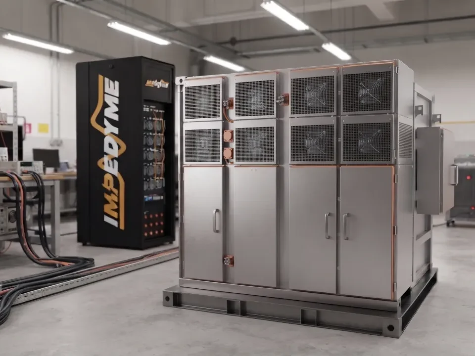
In a PHIL setup, the inverter control unit is tested along with a real 300 kW motor inverter at actual power levels. Instead of connecting a real motor and battery, the bench emulates the electric motor and the batteries at rated power using regenerative power amplifiers. The CHP Series’ power stage sources and sinks real current and voltage, so the inverter experiences genuine electrical loading. Low-latency fiber-optic communication links the power amplifier to the FPGA real-time core, keeping the closed loop stable at full power. 

The payoff: engineers verify the inverter design at full power without building a dynamometer, procuring a real traction pack, or risking hardware and personnel. PHIL delivers the realism of a full-power test with the safety, repeatability, and cost profile of simulation.

AttributeSignal-Level HILPower-Level PHIL
What crosses the interfaceLow-level signalsReal power (voltage & current)
Device under testController / logic boardController + full power stage (e.g., 300 kW inverter)
Emulation hardwareI/O modules, signal conditioningRegenerative power amplifiers (CHP Series)
Primary risk validatedControl logic, comms, faultsPower-stage behavior at rated power
Real motor/battery needed?NoNo — emulated at full power
CommunicationAnalog/digital I/OLow-latency fiber-optic
Representative of real operationHigh for controlHighest — real power flow

Demonstration 3: More Electric Aircraft Emergency Power

Electric aircraft HIL testing is not limited to eVTOL propulsion. Consider a more electric aircraft emergency power system that combines a fuel cell, a lithium-ion battery, and an ultracapacitor — a hybrid architecture designed to keep essential systems alive when primary generation fails. 

A HIL bench can emulate this entire energy system and stage an emergency landing with a generator-failure scenario: the primary generator drops offline, and the power management controller must orchestrate the fuel cell, battery, and ultracapacitor to sustain flight-critical loads through the landing. The bench communicates with the real controller over an ARINC 429 avionics interface, exercising the same messaging the aircraft uses in flight. 

Staging a generator failure on a real aircraft is out of the question. On an FPGA-based HIL bench, it is a repeatable test case — one that can be run across dozens of energy-state and fault combinations, each producing traceable test evidence for the safety case.

Unit-Level vs System-Level Testing

Certification-grade programs test at two levels, and HIL supports both.

AttributeUnit-Level TestingSystem-Level Testing
ScopeSingle controller or component (e.g., MCU or BMS)Integrated systems working together (powertrain + BMS + controls)
Question answeredDoes this unit meet its requirements?Do the units interact correctly and safely as a system?
FaultsComponent-level fault insertionCross-system fault propagation and interaction
Impedyme toolsCHP Series + relevant Software moduleCHP Series + PowerHIL Studio orchestration across emulators
Certification valueVerifies low-level requirementsVerifies high-level and integration requirements

Impedyme’s platform scales from a focused unit-level bench to a full system-level e-bird because every emulator — MotorSim Studio, BatterySim Studio, GridSim Studio, DroneSim Studio — runs on the same CHP hardware and is orchestrated from one PowerHIL Studio environment.

eVTOL Powertrain Validation: High-Fidelity Twin Simulation


Unit-Level vs. System-Level Testing Workflows

Validating a complex eVTOL propulsion system requires a progressive testing strategy, starting at the individual component level (unit-level) and moving up to full-scale multi-system integration (system-level) :

  • Unit-Level Validation: Focuses on isolating a single controller (such as a Battery Management System or a Motor Control Unit) . This step isolates the controller from external noise and verifies that its specific firmware, logic boundaries, and sensor front-ends perform as expected.
  • System-Level Validation: Integrates all individual controllers (e.g., the primary Flight Control Computer, multiple Motor Control Units, and the central Battery Management System) into a unified real-time test environment . System-level testing validates cross-communication protocols (such as CAN-FD messaging rates), latency propagation, power distribution transients, and multi-controller fault handling .

The eVTOL Digital Twin Architecture

To validate flight operations in real time, the HIL simulator must run a highly complex, multi-domain digital twin of the eVTOL aircraft . This digital twin consists of several interconnected mathematical submodels :

  • Flight Controller Submodel: Runs the virtual autopilot or flight computer, converting operator inputs and path navigation coordinates into motor speed commands.
  • Propulsion Submodel: Simulates the four (or more) rotary propulsors, including permanent magnet synchronous motors (PMSM) and three-phase inverter drives .
  • Energy Storage Submodel: Models the high-voltage battery pack (typically simulated around 400V or 800V depending on the aircraft class) and cell-balancing circuitry .
  • Flight Dynamics Submodel: Incorporates gravitational vectors, air density, wind shear, gyroscopic forces, and lifting aerodynamics to compute the vehicle’s actual movement in three-dimensional space.

By linking these models together in a closed-loop real-time environment, engineers can observe how a momentary drop in battery voltage affects motor thrust, and how that thrust reduction impacts the aircraft’s altitude and flight path .

Unreal Engine Photorealistic Visualization and Guidance Testing

To validate mission-level guidance, navigation, and control (GNC) algorithms, modern HIL setups integrate the real-time simulation engine with photorealistic 3D visualization environments, such as Epic Games’ Unreal Engine .

Using the custom workflow of specialized UAV simulation toolboxes, the aircraft’s 3D spatial coordinates are streamed from the real-time dynamics model directly to the visualization engine . This displays the aircraft flying within highly detailed, photorealistic urban environments.

During a guidance test, the operator can monitor the vehicle’s automated takeoff, transition to forward flight, hover adjustments, and vertical landing . The real-time interface displays motor speeds, terminal battery voltage, state of charge, and total current draw, enabling engineers to assess how environmental factors like crosswinds and turbulence impact battery life and propulsion efficiency.

Frequently Asked Questions 

How is HIL different from PHIL (Power Hardware-in-the-Loop)? 

Signal-level HIL exchanges low-level signals between the controller and the simulated plant, validating control logic, communication, and fault handling. PHIL goes further by exchanging real power: a regenerative power amplifier drives the device under test — such as a 300 kW inverter — at rated voltage and current against an emulated motor or battery. PHIL verifies power-stage behavior at full power without a real dynamometer or battery pack. 

Which standards govern electric aircraft certification? 

The core stack is ARP 4754B (aircraft and system development), DO-178C (airborne software), DO-254 (complex electronic hardware), and DO-160 (environmental conditions). ARP 4754B was released on December 20, 2023 and aligns with the ARP 4761A safety assessment process. HIL supports the requirements-based verification objectives of these standards.

Do regulators accept HIL and laboratory simulation as means of compliance? 

Yes. Both EASA and the FAA describe compliance demonstration as a blend of analysis, simulation, ground tests, and flight tests. EASA’s SC-VTOL Means of Compliance documents explicitly address qualifying simulation benches and test rigs for compliance demonstration and system development assurance, and validated simulation is a recognized method used to support and reduce physical testing.

Can HIL testing validate a battery management system without real cells? 

Yes. A battery emulator such as Impedyme’s BatterySim Studio, running on the FPGA-based CHP platform, reproduces cell, module, and pack behavior in real time. It emulates individual cell voltages (scaling via daisy-chaining up to 252 cells), emulates temperature and current sensors, and injects faults — short circuits, broken wires, voltage and temperature overrides — so the BMS controller and cell monitoring units are validated safely and repeatably, including cell-balancing verification.

What is the difference between RCP and HIL? 

In rapid control prototyping (RCP), the controller algorithm is emulated on a flexible real-time target (Impedyme’s RCP-Box) and runs against a real plant or iron bird to iterate control strategy quickly. In HIL, the controller is the real production hardware and the plant is emulated on the CHP Series — used to verify production hardware and code for robustness and certification readiness. They sit on opposite arms of the model-based design V-model.