The global electrical infrastructure is undergoing a profound paradigm shift. Traditional power grids, which historically relied on centralized, fossil-fueled thermal plants with massive rotating synchronous machines, are being rapidly decommissioned in favor of decentralized, zero-carbon alternatives. According to the International Energy Agency, the combined output of solar and wind energy is projected to soon surpass coal as the largest source of electricity worldwide. This massive influx of distributed energy resources, coupled with the rapid adoption of utility-scale battery energy storage systems, electric vehicles, and high-efficiency wide-bandgap power semiconductor converters, has restructured modern distribution and transmission networks.
However, transitioning to a grid dominated by converter-interfaced generation introduces substantial technical challenges. Unlike synchronous generators that provide inherent physical inertia to buffer frequency changes, converter-based resources exhibit little to no physical inertia. Consequently, minor grid faults or load variations can lead to severe voltage and frequency instability. To ensure stable operation, meet stringent grid codes, and protect multi-million-dollar power assets, grid innovators require high-fidelity testing solutions. Hardware in the loop testing for microgrids and hardware in the loop testing for renewable systems have transitioned from niche academic options into necessary industry standards for validating complex controllers, protection relays, and power electronic converters.
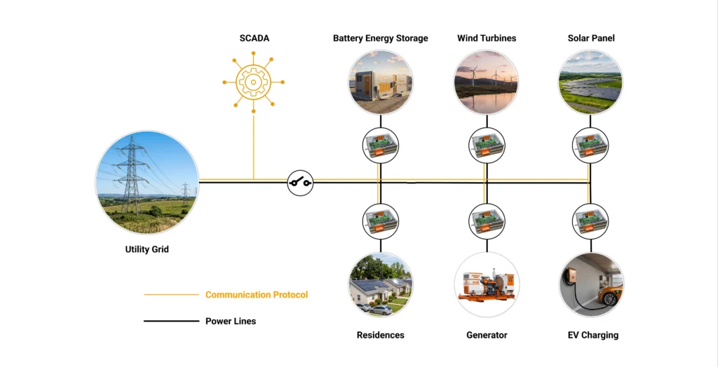
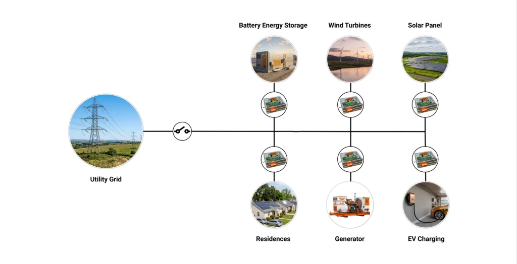
A modern microgrid is a control problem disguised as a power system. Photovoltaic inverters, battery energy storage systems, wind turbines, diesel gensets, and controllable loads all interact through fast digital controls with very little of the rotational inertia that used to hold traditional grids stable. The behavior of protection, control, and power devices in this environment is nuanced and often unpredictable. A microgrid must deliver resilient, reliable power while operating securely across a wide range of conditions — grid-connected, islanded, and everything in between.
Testing that behavior on real hardware and a real grid is fraught. You cannot deliberately collapse a utility feeder to see whether your controller rides through. You cannot repeatedly short-circuit an expensive inverter to characterize its fault response. You cannot wait for a cloudy, gusty winter afternoon to occur on demand. And you certainly cannot afford to discover, during commissioning, that your energy management system sequences breakers in the wrong order during an unplanned island.
HIL testing resolves all of these problems at once. The physical device you care about — the controller, the inverter, the relay — is connected to a real-time simulation of the rest of the world. The controller cannot tell the difference. It reads the same sensor signals, drives the same actuators, and speaks the same communication protocols it will use in the field. But the “grid” it interacts with is a mathematical model running deterministically on a target machine, which means you can fault it, break it, and push it to extremes as many times as you like, at any hour, without risk to people or property.
The payoff is concrete: safe validation without risking the utility grid or expensive equipment; testing across every real signal interface; automated, unattended 24/7 test campaigns; the ability to reproduce fault and extreme conditions that are impossible on real hardware; and early validation of control software long before the final power hardware exists.
The concept that makes this work is the digital twin: a high-fidelity plant model that runs in real time on a target machine and behaves, from the controller’s perspective, exactly like the real plant. “Real time” is the critical qualifier. An offline simulation can take as long as it needs to compute one millisecond of plant behavior. A real-time simulator must compute that millisecond in one millisecond — every millisecond, forever — so that the hardware under test experiences physically correct timing, sensor delays, quantization, and I/O response.
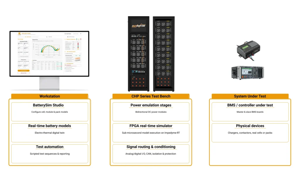
A complete HIL test system has three components:
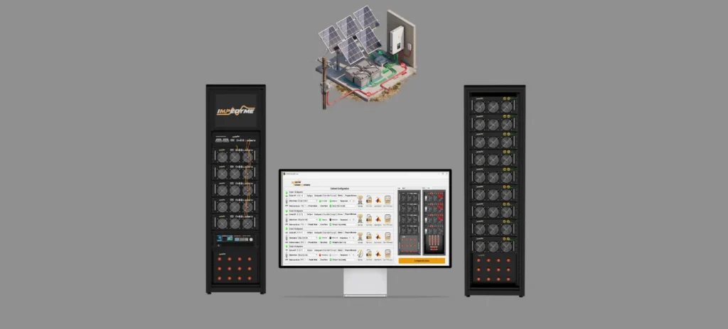
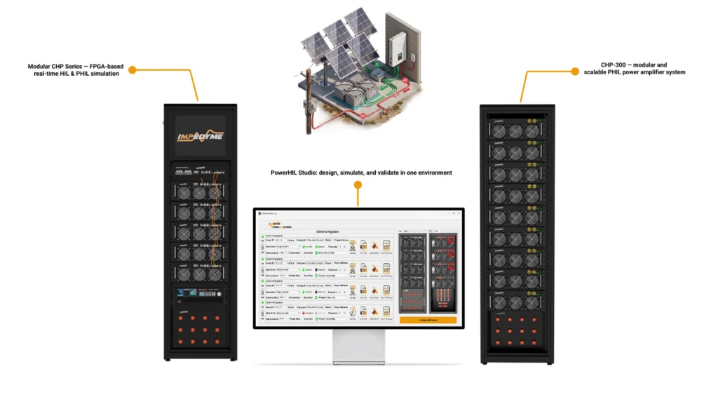
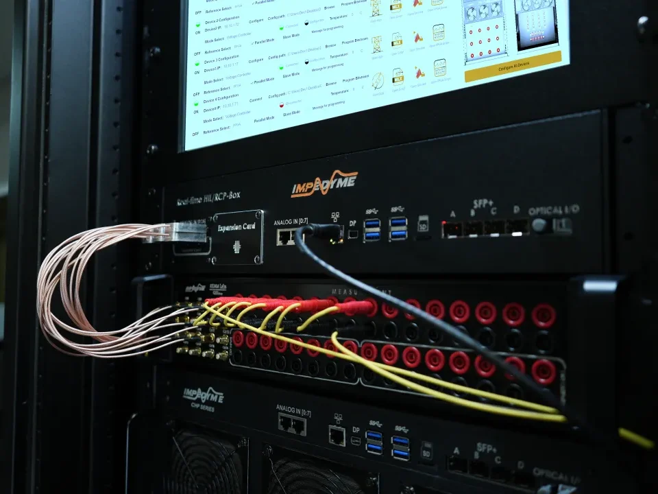
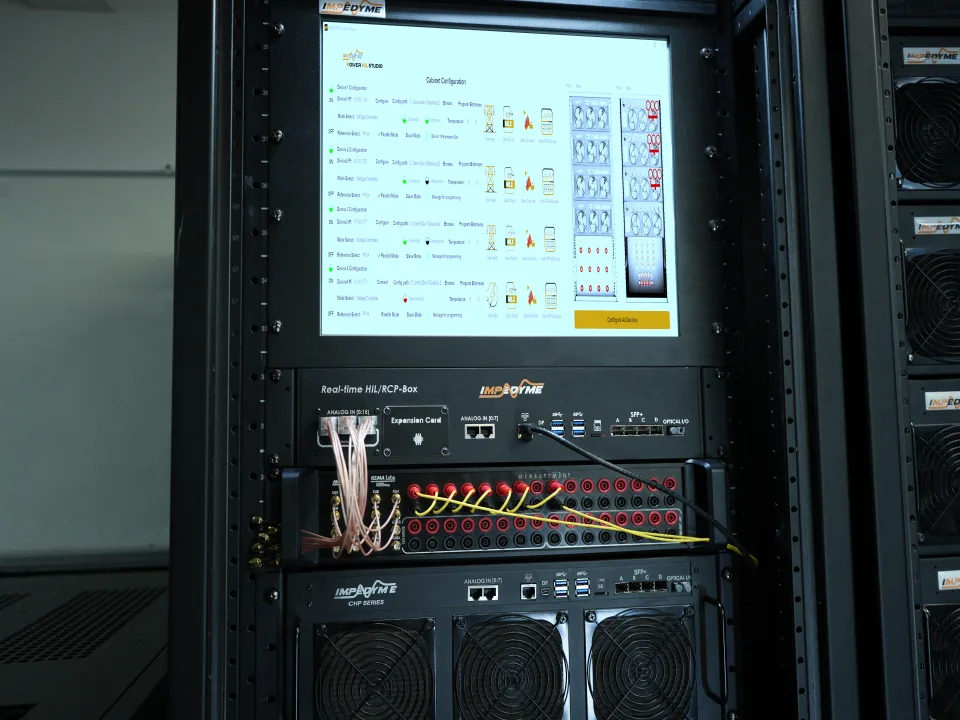
Impedyme’s CHP Series is a combined HIL and Power HIL (CHP) platform built around the Impedyme-RT real-time engine and a regenerative power interface. It runs the plant model on FPGA fabric with simulation time steps as low as 90 nanoseconds, and its multi-channel analog I/O, digital I/O, and multi-gigabit fiber links connect directly to the hardware under test. Because signals are directly accessible in a Simulink-integrated workflow, engineers move from model to real-time target without rewriting their work.
There is an important distinction inside the validation gap itself. Traditional controller HIL (CHIL) exchanges only low-power signals: the simulator feeds voltages and currents as measurement-level analog signals to the controller, and reads back the controller’s gate commands or setpoints. This validates control logic, communication, and interface quality superbly, but the controller never drives real power.
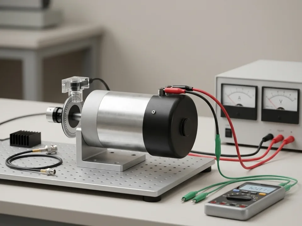
Power HIL (PHIL) closes the remaining gap. Here the real-time simulation exchanges actual power with a physical device — an inverter, a battery, a motor, a load — through a bidirectional, regenerative power amplifier. Now the device under test sees real current and real voltage, so you can confirm power-stage behavior, thermal response, protection timing, and control stability under genuine electrical stress. Many discussions of microgrid HIL stop at the signal level; the deeper, more valuable capability is bringing power into the loop.
PHIL introduces its own engineering discipline. The power interface is not ideal: amplifier bandwidth, measurement noise, and loop delays introduce artifacts that can destabilize the closed loop if ignored. The peer-reviewed literature identifies interface algorithms — among them the ideal transformer method (ITM) and the damping impedance method (DIM), analyzed in work such as Ren, Steurer & Baldwin, “Improve the Stability and Accuracy of Power Hardware-in-the-Loop Simulation” (IEEE Transactions on Industry Applications, 2008) — and shows that the choice and tuning of the interface algorithm determine whether a PHIL loop is stable and accurate. A well-designed PHIL bench minimizes these effects through interface algorithm design and delay compensation, characterizes them through sensitivity analysis, and documents them alongside test results.
A practical rule that governs PHIL fidelity: the power amplifier’s response time should be at least twice as fast as the simulation time step, so the amplifier can track the signals the model generates without introducing destabilizing lag. The Impedyme CHP Series was designed around this principle, co-designing its regenerative amplifiers with the FPGA simulation core so that amplifier rise and fall times align with real-time simulator time steps.
Not all real-time simulation is equal, and this is the single most important technical decision in renewable-energy HIL. The determining factor is the simulation time step: how often the model state is recomputed. A robust guideline is that the time step must be at least ten times smaller than the period of the fastest waveform you need to resolve.
CPU-based real-time simulators typically achieve time steps in the range of tens of microseconds. That is entirely adequate for control-loop dynamics, grid synchronization, harmonics to moderate order, and converters switching up to roughly 10 kHz. For a grid-tied inverter control loop with a 2 kHz bandwidth, a time step of 50 microseconds is fine.
But modern power electronics have outrun CPUs. Wide-bandgap silicon-carbide and gallium-nitride converters switch at 100 kHz and beyond, with switching transients measured in tens of nanoseconds. To simulate these accurately you need nanosecond-to-microsecond time steps — and only an FPGA can compute a full converter model that fast, because its logic cells run the model’s equations in massively parallel, deterministic hardware rather than sequentially. Published research bears this out precisely: an FPGA implementation of the Latency Insertion Method on a Xilinx Virtex-7 simulated SiC-based converters switching at 100–200 kHz with “time steps of 40ns and smaller,” while Bai et al. (IET Power Electronics, 2019) simulated a fuel-cell-electric-vehicle power-electronic system “with sub-microsecond time-step while producing the detailed switching waveforms with 5 ns resolution” for converters up to 100 kHz.
This is the crux of the validation gap for power electronics: without FPGA-class execution, you simply cannot represent a high-switching-frequency converter in real time at all. The Impedyme CHP Series runs its models on FPGA fabric with 90-nanosecond time steps — roughly eleven million model updates per second — spanning from sub-microsecond switching transients up to the slower electromechanical behavior of the surrounding grid on a single platform.
| Attribute | CPU-based simulation | FPGA-based simulation |
|---|---|---|
| Typical time step | Tens of microseconds | Nanoseconds to low microseconds (as low as 90 ns on CHP Series) |
| Converter switching frequency | Up to ~10 kHz | 100 kHz to 1 MHz+ (SiC/GaN) |
| Best-fit tasks | EMS logic, grid synchronization, control loops, low-order harmonics | Detailed switching transients, wide-bandgap converters, fast protection, PHIL power interface |
| Model execution | Sequential across cores | Massively parallel, deterministic |
| Fidelity limit | Cannot resolve fast switching transients | Resolves nanosecond-scale switching events |
| Role in the gap | Bridges offline to control validation | Bridges control validation to real hardware / power |
The practical approach is not CPU or FPGA but the right resolution for the fastest dynamics in play — and a platform that can host both, so a single test bench spans EMS logic and sub-microsecond converter switching without changing environments.
The microgrid energy management system (EMS) is the brain of the installation. Under the IEEE 2030.7 framework it is defined as a microgrid control system with two core functions: the dispatch function, which allocates microgrid assets across grid-connected and islanded states, and the transition function, which connects to and disconnects from the grid. IEEE 2030.8-2018 is the companion standard that defines how to test those functions — in the words of the standard, to allow “the verification, the quantification of the performance, and a comparison of the performance with expected minimum requirements of the different functions of the microgrid controller.”
A typical EMS runs on a PLC and communicates over fieldbus and SCADA protocols. HIL testing lets you validate its behavior against a real-time digital twin of the microgrid without a single real asset connected:
Because the entire microgrid is modeled, you can run these sequences repeatedly and automatically. National laboratory HIL work illustrates the scale: NREL’s controller-hardware-in-the-loop evaluation of the Bronzeville Community Microgrid (Xie et al., IEEE ECCE 2024) ran islanded-energy-management cases that started from black start and sustained coordinated generation for up to 24 hours using detailed EMT modeling and DNP3 protocols — a duration and repeatability only feasible in a simulated environment.
A solar inverter controller is a demanding HIL target because it must react continuously to two independent, fast-changing worlds: the DC side (a photovoltaic array whose output swings with irradiance and temperature) and the AC side (a grid that sags, swells, shifts frequency, and occasionally faults).
Consider a three-level neutral-point-clamped (NPC) inverter — a topology favored for grid-connected PV because it achieves lower harmonic distortion than a two-level design. To validate its controller, the HIL bench must emulate:
Here the CPU-versus-FPGA distinction becomes tangible. For the inverter’s control loops and grid synchronization, a CPU-class time step of tens of microseconds suffices. But to represent the NPC inverter’s actual switching behavior — the ripple, the neutral-point balancing dynamics, the device-level transients — you need FPGA-based simulation with nanosecond-to-microsecond time steps. GridSim Studio drives this on the CHP Series with drag-and-drop grid-profile creation: programmable voltage and frequency profiles, fault and disturbance waveforms, and real-time grid-impedance modeling, all sequenced into automated ride-through and compliance runs.
As inverter-based resources displace synchronous machines, the industry is shifting from grid-following to grid-forming controls, and HIL is the only safe place to characterize the difference.
A grid-following inverter behaves as a current source synchronized to an external voltage reference through a phase-locked loop. It works well on strong grids but becomes unstable in weak grids with a low short-circuit ratio, precisely because it depends on a stiff reference that a weak grid cannot provide. A grid-forming inverter behaves as a controlled voltage source: it establishes its own voltage magnitude, angle, and frequency, acting as the stability anchor during weak-grid operation, islanding, and black start. Grid-forming controls can also synthesize virtual inertia — injecting a fast, programmable burst of active power in response to frequency change, emulating the physical inertia of a spinning machine.
These behaviors must be validated as waveform authority: inner voltage loops, virtual impedance, current-limit logic, and energy-reserve management all enter the critical path, and poor tuning that looks calm in a static study can lose synchronism the moment a load step, saturation, or measurement lag appears. HIL lets you stage exactly those stressors:
GridSim Studio’s real-time grid-impedance modeling — running on the FPGA with nanosecond-level response — lets engineers replicate stiff, weak, or dynamically changing networks and observe how a controller reacts to the exact disturbances it will face in the field.
Protection is where microgrid behavior gets genuinely counterintuitive. Inverter-based resources supply limited, controlled fault current — nothing like the large, sustained fault current of a synchronous machine — so relay curves that were fine for a conventional grid can nuisance-trip or fail to trip when inverters dominate. HIL testing of protection relays, with the relay in the loop against a real-time fault model, is the way to catch these misoperations before they endanger line workers or equipment.
Modern digital substations communicate over IEC 61850. A capable HIL bench must speak this language natively:
With these interfaces, engineers can simulate fault conditions to verify communication between relays and breakers, validate correct fault detection and isolation, confirm interoperability across multi-vendor devices, and even inject protocol-level faults — packet delays, duplication, and communication cut-outs — to test the scheme’s resilience. Impedyme’s HIL Protection application and the CHP Series support this closed-loop protection testing directly.
The strongest reason to invest in HIL is that it turns standards compliance from a paperwork exercise into repeatable, automated engineering evidence. GridSim Studio explicitly supports IEEE 1547, UL 1741, and IEC 61000 test profiles. The tables below map common requirements to HIL test scenarios.
| Requirement | What it verifies | HIL/PHIL test approach |
|---|---|---|
| Unintentional islanding (IEEE 1547-2018) | DER ceases to energize within the required time after island formation | Force balanced-load island in the model; measure run-on time |
| Voltage ride-through (Categories I/II/III) | DER stays connected through voltage sags/swells | Programmable voltage-sag profiles at the terminals |
| Frequency ride-through | DER rides through abnormal frequency within defined bands | Frequency steps, ramps, and RoCoF events |
| Reactive power / volt-VAR | DER supplies reactive power as a function of voltage | Voltage sweeps against Q(V) curves |
| Low-voltage ride-through (LVRT) | Inverter injects reactive current and recovers on voltage recovery | Staged voltage dips with reactive-current measurement |
| Anti-islanding | Inverter disconnects quickly from a dead line | Balanced-load islanding event; measure disconnect time |
| Power quality / harmonics | Output stays within distortion limits | Harmonic injection and THD measurement |
Per IEEE 1547-2018, a distributed energy resource must “detect and cease to energize an unintentional island within two seconds of formation, or before the first reclose interval of the device that formed the island” (some utilities may extend the unintentional-islanding clearing time to as much as five seconds under EPRI DER-settings guidance). The standard also defines three abnormal-operating-performance categories (I, II, III) with progressively wider ride-through, and default frequency trip settings for 60 Hz systems. GridSim Studio can sequence each of these as an automated, repeatable campaign with pass/fail criteria — proof that scales across firmware revisions.
Beyond the headline use cases, a mature HIL platform earns its keep through breadth of capability:
Two capabilities separate a demonstration from a validation program.
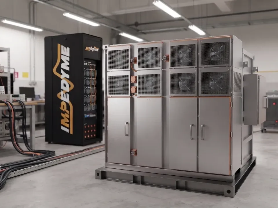
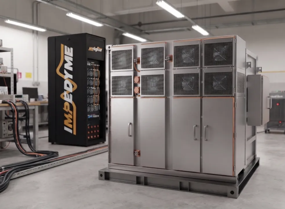
Scaling with multiple simulators. A single cabinet handles a converter or a small microgrid, but real distribution-scale studies require more compute and more I/O. Impedyme’s platforms are modular and built from power and FPGA units that scale from kilowatts to multi-megawatt setups, with cabinets that can be paralleled for high-power systems — so you add channels and racks as project scope grows rather than buying a monolithic system up front.
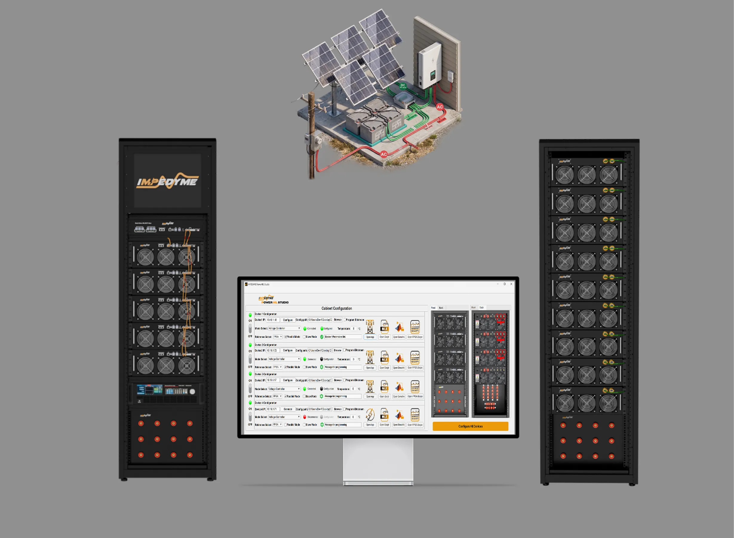
Test automation and continuous integration. The greatest long-term value of HIL is that it makes power-electronics testing behave like software testing. Historically, testing every firmware commit in a power lab was too slow and too expensive to be practical. HIL changes that: every code change can trigger a closed-loop test suite, with each test controlling its initial state, applying a defined stimulus, and asserting a numeric pass/fail rule tied to safety or timing. PowerHIL Studio provides exactly this orchestration layer — a scenario and sequence editor, synchronized control of grid, battery, and load emulation, tight integration with a Simulink-based workflow and MATLAB scripting, automated pass/fail criteria and reporting, and configurable safety limits with controlled shutdown. Combined with FPGA Scope for high-resolution waveform capture, engineers get a versioned, traceable paper trail of results that stays consistent across months of development — the foundation for a continuous-integration pipeline in power electronics.
A comparison of system architectures highlights the performance advantages of Impedyme’s CHP platform over legacy real-time testing systems
| Technical Parameter / Feature | Legacy Monolithic Simulators | Impedyme Next-Generation CHP Platform | Strategic and Engineering Value |
|---|---|---|---|
| System Integration and Toolchain | Closed, proprietary platforms with separate modeling and execution packages. | Unified open-source HIL framework with MATLAB, Simulink, and Python integration. | Streamlines development by utilizing the same simulation models from early desktop design through high-power validation. |
| FPGA Processing and Co-Execution | Limited to fixed-configuration modules or complex custom HDL compilation. | User-programmable UltraScale+ FPGA with integrated compiler workflows. | Enables rapid control prototyping and dynamic parameter tuning directly on the FPGA fabric. |
| Power Hardware (PHIL) Capability | Requires integrating separate non-regenerative power amplifiers. | Integrated fully regenerative four-quadrant power stage up to 550 kVA+. | Minimizes interface delays, improves PHIL loop stability, and reduces laboratory electricity costs. |
| Simulation Step-Time Performance | Fixed execution steps typically limited to microsecond-level loops. | Adaptive scheduler executing steps as low as several nanoseconds on FPGA. | Captures high-frequency switching transitions and dead-time effects in wide-bandgap power converters. |
| Substation Protocol Support | Basic digital/analog I/O, often requiring external protocol converters. | Native integration of IEC 61850 (GOOSE/SV), Modbus, PROFINET, and CAN-FD. | Simplifies validation of multi-device smart grid automation and communication networks. |
| Cooling and Noise Control | Loud, high-speed fan cooling with large external chillers. | Integrated liquid-to-air cooling within a compact cabinet footprint. | Improves thermal stability, increases hardware lifespan, and reduces laboratory noise. |
To maximize the value of hardware-in-the-loop and power hardware-in-the-loop validation for modern power systems, engineers should focus on several strategic areas:
Transitioning from early-stage software design to real-time HIL and PHIL validation can introduce model compatibility issues. Grid innovators should utilize a model-based toolchain that integrates with industry-standard environments like MATLAB and Simulink.
By using the same core models throughout the project, development teams can avoid rewriting code, speed up validation, and ensure consistent behavior from software-in-the-loop to full-power hardware testing.
With the drop in physical grid strength caused by the rise of converter-interfaced renewables, grid-forming control strategies are essential for maintaining system stability.
Engineers must validate GFM algorithms under realistic weak-grid and islanded conditions. Closed-loop real-time simulation is necessary to verify virtual inertia damping, phase-locked loop stability margins, and current-limiting transitions during close-in short-circuit faults.
Manually running individual simulation tests is time-consuming and limits coverage. Development teams should leverage automated testing frameworks within their real-time environments to execute continuous testing sweeps.
Scripting automated sequences for load changes, weather transitions, communication failures, and grid faults ensures that converter firmware is fully validated across all operating boundaries.
High-power PHIL testing requires significant electrical energy, which can drastically increase operating costs. When validating high-power grid-connected inverters or battery energy storage systems, teams should utilize bi-directional regenerative power emulators.
By recirculating power internally within the emulator cabinet, labs can limit energy draw to only the physical losses of the system, minimizing utility requirements and operating expenses.
Why does FPGA-based simulation matter for renewable energy HIL?
Wide-bandgap converters switch at 100 kHz and beyond, with nanosecond-scale transients. Only FPGA-based simulation, which runs the model in massively parallel hardware, achieves the nanosecond-to-microsecond time steps needed to represent these accurately. CPU-based simulators are typically limited to converters switching up to about 10 kHz.
Can HIL testing start before the final hardware is built?
Yes. Controller HIL lets you validate control software against a real-time plant model long before the final power hardware exists, catching logic and interface issues at the cheapest possible stage.
How does HIL support continuous integration for power electronics?
Every firmware commit can trigger an automated closed-loop test suite with numeric pass/fail rules, giving power-electronics teams the same fast feedback and regression protection that software teams expect — something that was impractical when every test required a physical power lab.
What is virtual inertia and how is it tested?
Virtual inertia is a fast, programmable active-power response that a grid-forming inverter injects when frequency changes, emulating a spinning machine’s inertia. It is tested by applying high-resolution frequency steps, ramps, and rate-of-change events and confirming the inverter responds per its droop and inertia settings.
What products does Impedyme offer for microgrid and renewable HIL?
The CHP Series combines controller HIL and Power HIL in one FPGA-based, regenerative platform. GridSim Studio handles grid emulation and compliance profiles, BatterySim Studio models storage, FPGA Scope captures waveforms, and PowerHIL Studio orchestrates automated test campaigns — all through a Simulink-integrated workflow.