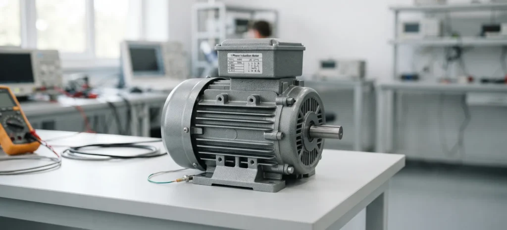
one phase induction motor card

Application knowledgeGridMotorProduct knowledge

one phase induction motor header

Single Phase Induction Motor

The single phase induction motor is the most widely used electric motor in the world, found in refrigerators, pumps, air conditioners, workshop tools and nearly every ventilation fan. It runs directly from the single-phase supply that powers homes, farms and small businesses, and it needs no brushes, no commutator and very little maintenance. Its simplicity hides an engineering problem, though: a 1 phase induction motor produces no starting torque on its own, which is why a single phase induction motor is not self starting. This guide explains the single phase motor working principle, the main types of single phase induction motors, and how they compare in a single phase vs three phase induction motor choice. It ends with how engineers troubleshoot, test, validate and select a one phase induction motor or single phase induction machine, drawing on Impedyme’s experience in real-time testing and power hardware in the loop.

What is a single phase induction motor?

A single phase induction motor is an AC motor that runs from a single-phase supply and turns electrical energy into shaft rotation through electromagnetic induction. Nothing is wired to the rotating part.

In practice, the 1 phase induction motor has two stator windings, a main (running) winding and an auxiliary (starting) winding, wrapped around a squirrel-cage rotor. It has no brushes, commutator or slip rings. The machine is asynchronous: the rotor always turns a little slower than the stator field. That speed difference, called slip, is what induces rotor current and torque. At rated load, slip is typically 3–6 %.

Ratings run from a few watts in small fans to about 3 kW in pumps and compressors. Supplies are 110–120 V or 220–240 V at 50 or 60 Hz. Pole count and supply frequency set the speed:

PolesSynchronous speed (60 Hz) / Typical full-load speedSynchronous speed (50 Hz) / Typical full-load speed
23600 rpm / ≈3450 rpm3000 rpm / ≈2850 rpm
41800 rpm / ≈1725 rpm1500 rpm / ≈1425 rpm
61200 rpm / ≈1140 rpm1000 rpm / ≈950 rpm
8900 rpm / ≈860 rpm750 rpm / ≈710 rpm

Here is a worked example. On a 60 Hz supply, a four-pole motor’s field turns at 1800 rpm. At full load the rotor falls behind by about 4 %, so the nameplate reads close to 1725 rpm. The same motor on 50 Hz reads about 1425 rpm.

Homes, farms, small workshops and most light-commercial buildings get only single-phase service. That makes the single phase induction machine the default motor wherever three-phase power is unavailable. It also has one built-in weakness that shapes the rest of this article: on its own, it cannot start. Every variant described below exists to solve that starting problem.

Construction of a single phase induction motor

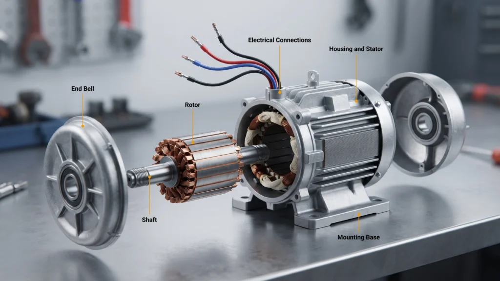
The single phase induction motor has five assemblies: the stator and its two windings, the squirrel-cage rotor, the bearings and end shields, the enclosure and cooling system, and the starting components (switch or relay plus capacitors). Mechanically it is very close to a small three-phase motor. The only electrical difference is on the stator side, where two windings and their starting hardware take the place of a balanced three-phase winding. North American motors use fractional- and integral-horsepower frame designations. Elsewhere, IEC frame sizes based on shaft height apply. Enclosures are described as open drip-proof or totally enclosed, or by an IEC ingress-protection code such as IP44, IP54 or IP55.

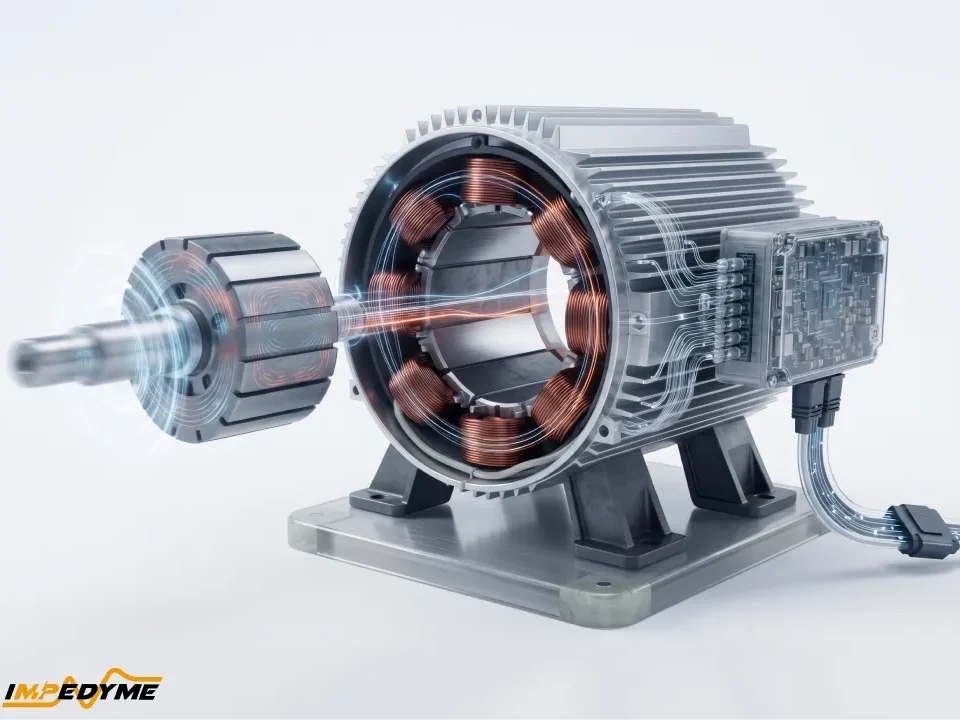
Stator: main winding and auxiliary winding

In a 1 phase induction motor, the stator core is a stack of thin, insulated silicon-steel laminations. Laminating the core keeps eddy-current losses down. Small machines commonly have 24 or 36 slots, and insulated copper (sometimes aluminum) coils are distributed through them.

The two windings are built for opposite jobs:

  • Main (running) winding: heavier wire with more turns, placed deep in the slots where the surrounding iron raises its inductance. The result is low resistance and high reactance, so its current lags the supply voltage by a large angle.
  • Auxiliary (starting) winding: finer wire with fewer turns, placed nearer the slot openings. The result is high resistance and low reactance, so its current lags far less.

The two windings sit 90 electrical degrees apart in space. That spacing is only half of what a rotating field needs. The other half is a time difference between the two currents. Every starting method in this article, whether resistance, capacitor or shading coil, exists to create a time-phase difference between the currents in these two windings.

Rotor: the squirrel cage

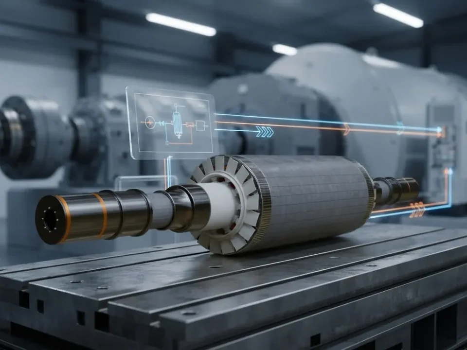
The rotor is a laminated steel core whose slots hold aluminum bars (copper in some premium designs), usually die-cast in one shot. End rings short the bars together at both ends. The cage has no electrical connection to the supply; all of its current is induced. The bars are skewed, set at a slight angle along the stack, to reduce cogging, slot-harmonic torques and magnetic whine.

Wound rotors are essentially never used in a single phase induction machine. Slip rings and brushes would add cost, maintenance and sparking to a machine whose whole appeal is being simple and sealed. Rotor resistance is still a design lever, set through bar material and cross-section. Narrow bars or aluminum alloy raise resistance, which boosts starting torque but increases running slip and rotor loss. Large or copper bars do the reverse: lower slip and better efficiency, at the cost of weaker starting torque.

Bearings, air gap, cooling and thermal protection

Sleeve bearings, which are oil-impregnated bronze, are quiet and cheap. They suit low-load appliance fans and blowers. Ball bearings handle radial belt pull and axial thrust, and they belong in belt-driven pumps, compressors and workshop machines. The end shields hold the bearings concentric so the rotor sits in a small, uniform air gap, a few tenths of a millimetre in fractional-kilowatt machines. The gap is kept small because air is a poor magnetic path: every extra fraction of a millimetre raises magnetizing current and lowers power factor.

Cooling in a one phase induction motor comes from a shaft-mounted fan. Open drip-proof (ODP) enclosures pull air through the windings and suit clean indoor locations. Totally enclosed fan-cooled (TEFC) enclosures blow air over a finned frame and suit dusty, damp or outdoor sites. Insulation is usually Class B (130 °C) or Class F (155 °C). Most motors also carry a thermal protector, a bimetal disc or thermistor embedded in or against the winding, which opens the circuit on stall or sustained overload. It may reset automatically or manually.

Centrifugal switch, starting relay and capacitors

The auxiliary circuit has to be disconnected or reconfigured once the motor is up to speed. Several devices do this:

  • Centrifugal switch: spring-loaded weights on the shaft fly outward and open a stationary contact at roughly 70–80 % of synchronous speed. It is simple and speed-accurate, but the contacts arc and wear, and the mechanism adds axial length.
  • Current relay: its coil is in series with the main winding. The high inrush current pulls the contacts closed and energizes the start circuit. As the motor accelerates and main-winding current falls, the contacts drop out. It is common on small hermetic compressors.
  • Voltage (potential) relay: its coil sits across the start winding. As speed rises, the voltage induced in that winding climbs until the relay opens the start capacitor. It is widely used on capacitor-start capacitor-run compressors.
  • PTC and electronic starters: a positive-temperature-coefficient ceramic in series with the auxiliary winding conducts at first, then heats itself into a high-resistance state within about one to three seconds and passes only tens of milliamps afterward. These starters have no contacts, which is why sealed refrigerator compressors use them. The trade-off is that the PTC needs a few minutes to cool before it can restart the motor.  Electronic start modules sense current or phase shift instead and add diagnostics.

There are two capacitor families:

PropertyStart capacitorRun capacitor
ConstructionNon-polarized aluminum electrolyticMetallized polypropylene film, oil-filled or dry
DutyIntermittent; standard rating is 20 starts per hour of 3 s eachContinuous
Typical capacitance50–1200 µF2.5–100 µF
Typical voltage ratings110/125, 165, 220/250, 330 VAC370 or 440 VAC
ToleranceWide (often −0/+20 % or a µF range)Tight (about ±5–6 %)

How a single phase induction motor works

The single phase motor working principle starts with the main winding of the single phase induction motor. Alternating current in that winding produces a magnetic flux that stays fixed along the winding axis. It grows, collapses and reverses polarity twice per cycle, but it does not rotate. This pulsating flux cuts the rotor bars and induces currents in them, much as a transformer induces current in a shorted secondary. With the rotor of a 1 phase induction motor at rest, the forces on the bars push equally both ways around the shaft, and nothing happens except heat and hum. Once the rotor is already turning, the same pulsating field produces useful torque in the direction of rotation.

Engineers explain the behavior of a single phase induction machine with two complementary models: the double revolving field theory and the cross-field theory.

Double Revolving Field Theory of a Single Phase Induction Motor

A pulsating field fixed in space is mathematically identical to two fields of half its peak strength, rotating in opposite directions at synchronous speed. One is the forward field, the other the backward field. Each one acts on the rotor as if it were a separate three-phase-style motor.

At standstill, the rotor slips equally against both fields. The two torques are equal and opposite, so net torque is zero. Once the rotor turns, say forward, its slip against the forward field becomes small (a few per cent), while its slip against the backward field approaches 2, meaning the backward field sweeps past the rotor at nearly twice synchronous speed. At such high slip, rotor reactance dominates, the backward field induces large but poorly coupled currents, and its torque collapses. Forward torque wins, and the one phase induction motor keeps running in whichever direction it was pushed.

The model also predicts four practical consequences:

  • Extra rotor heating: the backward field induces rotor currents at nearly twice supply frequency, which adds copper loss without adding useful torque.
  • Double-frequency torque pulsation: the two fields interact to produce torque ripple at 100 Hz (50 Hz supply) or 120 Hz (60 Hz supply).
  • Audible hum and vibration: that ripple shakes the stator and mounts.
  • Higher slip: because the backward field drags on the rotor, slip is a little higher than in an equivalent three-phase machine for the same torque.

Cross-Field Theory of a 1 Phase Induction Motor

The cross-field picture of a single phase induction motor starts from the moving rotor. Spinning rotor conductors cut the stator flux and generate a speed EMF. That EMF drives rotor currents whose flux lies at right angles (in quadrature) to the stator axis and lags the stator flux by roughly a quarter cycle. Two fluxes 90° apart in space and roughly 90° apart in time combine into a field that rotates, close to circular near synchronous speed and fading to nothing at standstill.

The two models fit different jobs. Cross-field theory is the convenient way to understand running behavior and the quadrature field. Double revolving field theory is the one to use for torque-speed curves and equivalent-circuit work.

Why single phase induction motor is not self starting

At standstill in a single phase induction motor, the forward and backward torques are equal and cancel, so the starting torque is zero. The evidence is easy to see on a bench. A 1 phase induction motor with an open starting circuit hums loudly, draws close to full locked-rotor current and heats quickly. Give the shaft a firm spin by hand while it is energized and it accelerates and runs, in whichever direction it was spun.

That stalled state is dangerous. Locked-rotor current is typically five to eight times rated current.

The fix is simple: add a second winding whose current is shifted in time from the main winding current. That is exactly how the five motor types differ.

part of single phase induction motor

Torque-speed characteristics and matching the motor to the load

To read the torque-speed curve of a single phase induction motor, follow it from left to right:

  • Locked-rotor (starting) torque: torque at zero speed; it must exceed the load’s breakaway torque.
  • Pull-up torque: the lowest point during acceleration; the load must stay below it all the way up.
  • Breakdown torque: the peak. Push a 1 phase induction motor past it and the motor stalls. 
  • Full-load torque: the rated operating point, on the steep, nearly straight section just below synchronous speed. In this region, a small drop in speed produces a large rise in torque.

Typical starting torque as a percentage of full-load torque:

Motor TypeStarting Torque (% FLT)Breakdown Torque (% FLT)
Shaded-pole25–50%≈100–150%
Permanent split capacitor (PSC)50–100%≈150–200%
Split-phase100–175%≈200–250%
Capacitor-start200–300%+≈200–300%
Capacitor-start, capacitor-run (CSCR)200–300%≈200–300%

Load matching follows from the curve. Fans and centrifugal blowers have square-law torque: almost nothing at standstill, rising with the square of speed. A PSC or shaded-pole motor with a gentle curve suits them. Positive-displacement compressors starting against head pressure, loaded conveyors, and pumps with sticky seals or a partial jam need high breakaway torque, which means a capacitor-start or two-value capacitor motor.

The double-frequency torque pulsation is always present in a single phase induction machine. It is strongest in switch-type motors running on the main winding alone and weakest in motors with a well-sized run capacitor. It shows up as 100/120 Hz hum, as vibration passed into the frame, and as fatigue in rigid mounts. That is why appliance and HVAC fan motors are usually held in resilient rubber rings or isolation mounts.

Types of single phase induction motors and their starting methods

All five types differ in only two ways: how the auxiliary circuit creates the phase shift, and whether it stays connected once the motor is up to speed.

TypeStarting characteristicsEfficiency, power factor, rating, and uses
Split-phasePhase shift: Aux-winding resistance (≈25–30°); aux circuit: disconnected at speed; starting torque: 100–175% FLT; starting current: highPeak efficiency: 50–60%; power factor: 0.6–0.7; rating: 0.06–0.75 kW; uses: grinders, small belt fans, office machines
Capacitor-startPhase shift: Electrolytic capacitor (≈70–90°); aux circuit: disconnected at speed; starting torque: 200–300%+ FLT; starting current: moderatePeak efficiency: 50–65%; power factor: 0.6–0.7; rating: 0.18–1.5 kW; uses: compressors, jet pumps, conveyors
Two-value capacitor (CSCR)Phase shift: Start + run capacitor; aux circuit: run capacitor stays; starting torque: 200–300% FLT; starting current: moderatePeak efficiency: 60–75%; power factor: 0.8–0.95+; rating: 0.75–3 kW; uses: large pumps, air compressors, machine tools
PSCPhase shift: Run capacitor only; aux circuit: stays connected; starting torque: 50–100% FLT; starting current: lowPeak efficiency: 55–70%; power factor: 0.8–0.95+; rating: 10 W–0.75 kW; uses: fans, blowers, HVAC air handlers
Shaded polePhase shift: Copper shading ring; aux circuit: N/A; starting torque: 25–50% FLT; starting current: lowPeak efficiency: 20–40%; power factor: 0.5–0.6; rating: 2–100 W; uses: oven, freezer, and humidifier fans

Split-phase (resistance-start) induction motor

In a split-phase single phase induction motor, the high-resistance auxiliary winding produces only about 25–30 degrees of displacement between the two currents. That is enough to start the motor, but it makes a weak, elliptical field. A centrifugal switch (or a current relay in small hermetic units) disconnects the winding at roughly three-quarters of synchronous speed. Starting torque is modest. Starting current is high because the two currents are nearly in phase and add almost directly. Starting duty is strictly intermittent. Typical sizes for this 1 phase induction motor are 60 W to 0.75 kW, driving small belt-driven fans, bench grinders, washing machines and office machines. The dominant failure is frequent starting or slow acceleration that cooks the finely wound auxiliary winding.

Capacitor-start induction-run motor

An electrolytic start capacitor in series with the auxiliary winding pushes that winding’s current ahead of the voltage. That brings the displacement close to 90 degrees, giving the highest starting torque in the family at moderate starting current. The capacitor and auxiliary winding switch out at speed, so running performance is that of a plain single phase induction machine. Start capacitors range from roughly 60–110 µF on 1/4 hp to 216–300 µF on 1 hp 115 V motors, rated 125 or 250 VAC. Their duty limit is typically 20 starts per hour of about three seconds each. Exceeding it is the classic cause of a burst capacitor. Applications include refrigeration and air compressors, jet and well pumps, conveyors and farm equipment.

Capacitor-start capacitor-run (two-value capacitor) motor

This type adds a smaller, continuously rated film run capacitor that stays in circuit, alongside the large electrolytic start capacitor that a switch or voltage relay removes. It gets the high starting torque of the capacitor-start design, plus better running power factor and efficiency, lower running current and noticeably reduced 100/120 Hz pulsation, because the motor runs close to balanced two-phase at rated load. The costs are two capacitors, a switch or relay, and a higher price. It is the usual single phase induction motor choice for larger pumps, air compressors, woodworking and metalworking machine tools up to around 3 kW.

Permanent Split Capacitor (PSC) One Phase Induction Motor

A single run capacitor stays in series with the auxiliary winding at all times. With no switch and no relay, it is very reliable and the quietest small one phase induction motor. Because the capacitor is sized for running rather than starting, starting torque is low, which limits PSC motors to fans, blowers and direct-drive loads. Running efficiency and power factor are good. Because nothing switches with speed, the PSC tolerates voltage-based and drive-based speed control. When the main and auxiliary windings are identical, moving the capacitor from one winding to the other reverses rotation. That is how reversible gate and actuator motors work.

Shaded Pole Single Phase Induction Machine

The stator of a shaded pole single phase induction machine has salient poles. A heavy copper shading ring around part of each pole face delays the flux in that section, so the field sweeps from the unshaded to the shaded side and drags the rotor along. The motor is extremely simple and cheap, with no capacitor or switch. On the other hand, starting torque is very low, efficiency is poor (often 20–30 %, sometimes lower), and the direction is fixed by where the ring sits. Sizes run from a few watts to about 100 W in oven, refrigerator and freezer evaporator fans, humidifiers and small blowers. Efficiency regulations are steadily pushing these applications toward electronically commutated (EC) motors. An Oak Ridge National Laboratory study of commercial-refrigeration evaporator fans, sponsored by the US Department of Energy, puts state-of-the-art EC motors at approximately 66 % efficiency, against approximately 20 % for shaded-pole units and about 29 % for PSC motors.

Equivalent circuit of a single phase induction motor

The equivalent circuit of a 1 phase induction motor turns the double revolving field theory into a circuit diagram. It starts with the stator: winding resistance and leakage reactance in series, carrying the full line current. After that, the circuit splits into two series-connected sections. One represents the forward field and one the backward field. Each holds half of the magnetizing reactance and half of the rotor leakage reactance and resistance. The rotor resistance in each branch depends on slip. In the forward branch it looks very large near running speed, which represents converted mechanical power. In the backward branch it looks small, close to half its standstill value, which represents braking torque and extra heat.

At standstill the two branches are identical, which makes the zero starting torque obvious. Near rated speed the forward branch takes most of the voltage, and the backward branch becomes a small loss path.

With this circuit, engineers predict input current, power factor, torque, losses and efficiency at any slip from a handful of parameters, without building the single phase induction motor. The same parameters feed simulation models of the motor and its controller, including the real-time models that run on FPGA or CPU targets in Hardware in the loop work, where an appliance board or drive interacts with a simulated machine.

When the auxiliary winding stays connected, as in PSC and two-value motors, the simple model is not enough. The motor is treated as an unbalanced two-phase machine. Main and auxiliary currents are resolved into forward and backward components (the two-winding revolving-field model), and the capacitor and turns ratio appear explicitly.

No-load test and blocked-rotor test

These two bench tests extract the equivalent-circuit parameters of a single phase induction motor. Both are done with the auxiliary circuit open, except on capacitor-run designs, where the test plan must account for it.

No-load test. Run the one phase induction motor uncoupled at rated voltage and frequency, with the auxiliary circuit out once the motor is up to speed. Record voltage, current, input power and speed. Slip is nearly zero, so the input power is almost entirely core loss plus friction and windage. Repeating the test at several reduced voltages separates the two, because friction and windage stay constant while core loss falls with voltage. The current and power factor define the magnetizing branch.

Blocked-rotor test. Lock the shaft (with the auxiliary winding open, the motor will not start anyway). Raise a reduced voltage until rated current flows, then record voltage, current and power. Magnetizing current is negligible here, so the readings give the series impedance: stator plus rotor resistance and leakage reactance, and full-current copper loss.

Practical cautions:

  • Keep blocked-rotor readings to a few seconds; the winding heats fast with no cooling.
  • Record winding DC resistance and temperature before and after each test, and correct resistances to a reference temperature.
  • Use a true-RMS power analyzer. No-load current is distorted by saturation, and power factor is low, both of which defeat average-responding meters.
  • Use a programmable AC source rather than a variac, so voltage, frequency, waveform and ramp rate are identical from run to run and lab to lab.

Single phase vs three phase induction motor

A three-phase motor produces a constant-amplitude rotating field directly from its supply. A single-phase motor has to fake one. Nearly every difference between the two follows from that.

AttributeSingle phase induction motorThree phase induction motor
Self-startingNo; needs auxiliary circuitYes
Field typePulsating (forward + backward)Constant rotating
Starting torque25–300 %, depending on type150–275 % (NEMA Designs A–D)
Efficiency and power factorLower; 0.5–0.95 PF depending on capacitorHigher; typically 0.75–0.9 PF
Torque ripple and noiseInherent 100/120 Hz pulsationEssentially smooth
Frame size and weightLarger for the same outputSmaller, lighter
Locked-rotor current (1 hp, 230 V, NEMA limit)45 A31.3 A
Supply availabilityEverywhere, including homesIndustrial and commercial sites
Cost and maintenanceHigher per kW; switches and capacitors wearLower per kW; no starting parts
Practical ceiling≈3 kW typical; rare above 7.5 kWMegawatts

Above roughly 2 kW, a three-phase motor fed from a single-phase-input drive or a phase converter is usually the better answer. That route changes the installation. The drive’s input current is much higher per conductor than the motor’s line current, so feeders and breakers must be sized from the drive’s single-phase input rating. A three-phase-rated drive run on single-phase input is typically derated to about half its nameplate power. Motor cable length, shielding and grounding need attention. In exchange, the motor gets soft starting, variable speed and no starting switch to fail.

Speed control of single phase induction motors

There are three practical routes to control the speed of a single phase induction motor, each with limits:

  • Voltage control: tapped main windings, autotransformers or triac phase-angle controllers lower the voltage, so the 1 phase induction motor slips further down its torque curve. This works only for fan-type loads with high-resistance rotors, such as PSC and shaded-pole motors. Torque falls roughly with the square of voltage, slip losses become heat in the rotor, and low-speed torque disappears.
  • Pole changing: a winding reconnected for, say, 2 or 4 poles gives fixed discrete speeds. It is common in washing machines, multi-speed fans and appliance motors.
  • Drives: a single-phase-input, three-phase-output drive with a three-phase motor is the standard conversion. Dedicated single-phase drives for PSC motors exist. Most general-purpose drives, though, cannot feed a capacitor-run motor without rewiring: the run capacitor sees the drive’s fast-switching output, draws damaging current spikes, and its reactance changes with frequency. Split-phase and capacitor-start motors also misbehave because the centrifugal switch recloses at low speed.

Slip is unavoidable, because without it the rotor induces no current and makes no torque. As load rises, speed falls a few per cent. Where speed has to be tightly regulated, the usual answer is a different motor technology, such as an EC or permanent-magnet motor, or a three-phase motor on a closed-loop drive, rather than more control added to a single phase induction motor.

Efficiency, Losses and Power Factor of a 1 Phase Induction Motor

The loss budget of a single phase induction machine has five parts:

  • Stator copper loss: usually the largest, because one winding carries all the current.
  • Rotor copper loss: includes the extra loss from backward-field currents at nearly twice supply frequency.
  • Core loss: hysteresis and eddy currents in the laminations.
  • Friction and windage: bearings and the cooling fan.
  • Stray load loss: harmonic fluxes, slot effects and surface losses.

Typical full-load efficiency ranges from 20–40 % for shaded-pole motors and 50–60 % for fractional split-phase and capacitor-start machines, through 55–70 % for PSC motors, up to about 70–80 % for well-designed two-value capacitor motors at 1–3 kW. A small one phase induction motor loses out to its three-phase equivalent for structural reasons: one winding carries all the current, the backward field adds rotor loss without adding torque, and the larger magnetizing current in small frames drags the power factor down. NEMA reflects this in reverse by requiring small polyphase motors to deliver at least 140 % of the breakdown torque of a single-phase motor with the same rating.

In a single phase induction motor, the run capacitor supplies leading reactive current that offsets the lagging magnetizing current. That lifts the power factor from about 0.6–0.7 in switch-type motors to 0.8–0.95 or higher in PSC and two-value designs, and it lowers line current for the same output.

Expect derating when a 1 phase induction motor runs away from nominal conditions. Motors are generally designed for ±10 % voltage. At low voltage, torque falls with the square of voltage and current rises. At high voltage, magnetizing current and core loss climb. Above a 40 °C ambient or 1000 m altitude, output must be reduced to hold the insulation-class temperature limit.

Efficiency classes are defined by the IEC classification standard for line-operated AC motors (the IE code), which covers motors from 0.12 kW to 1000 kW, including the single phase induction machine. For a four-pole 50 Hz motor, the standard’s IE2 minimums are 59.1 % at 0.12 kW, 72.7 % at 0.37 kW, 79.6 % at 0.75 kW and 84.3 % at 2.2 kW. Losses are measured with the IEC loss test-method standard or the IEEE test procedure for single-phase induction motors, which US Department of Energy rules incorporate by reference for single-phase small electric motors. Since 1 July 2023, the European Union’s motor ecodesign regulation has required single-phase motors rated 0.12 kW and above to reach at least IE2, a level many shaded-pole and split-phase designs cannot reach.

Applications of single phase induction motors by industry

The right single phase induction motor for each industry follows from its torque curve and duty cycle:

  • HVAC and refrigeration: PSC motors drive condenser fans and air handlers because they are quiet and their low starting torque suits fan loads. Hermetic compressors use PTC- or relay-started split-phase or capacitor-start designs, or CSCR designs for larger units, because they must start against head pressure.
  • Water and wastewater pumping: jet, well and sump pumps use capacitor-start or two-value designs for breakaway torque against seal friction and standing head. Submersibles often use CSCR control boxes.
  • Agriculture: grain augers, feeders, barn ventilation and milk-cooling compressors use capacitor-start or CSCR motors on loaded starts, and PSC motors on ventilation fans.
  • Building services: circulators, door operators and ventilation fans use PSC motors, valued for reversibility and quiet operation.
  • Appliance and consumer products: washers use pole-changing or PSC motors, while dryers, dishwashers and range hoods use split-phase, PSC or shaded-pole motors chosen on cost and duty cycle.
  • Workshop machinery: table saws, drill presses, lathes and air compressors use capacitor-start or two-value motors for high breakaway torque and frequent loaded starts.
  • EV charging and telecom cabinet cooling: PSC or shaded-pole fans run continuously at fixed speed, where reliability matters more than efficiency.
  • Off-grid and solar pumping: solar inverter test  must tolerate the inverter’s inrush limit, so low starting current matters as much as torque.
  • Teaching laboratories: a split-phase or capacitor-start one phase induction motor with accessible switches illustrates starting, the equivalent circuit and no-load and blocked-rotor tests.

Single Phase Induction Motor Faults, Symptoms and Troubleshooting

Single phase motor hums but won’t start. The starting circuit is not producing a phase-shifted current, or the load is locked. Check for:

  • an open auxiliary winding
  • a failed start or run capacitor (open, or lost capacitance)
  • a centrifugal switch stuck open or a relay that does not pull in
  • a seized bearing or jammed load

A quick test: spin the shaft of the 1 phase induction motor by hand with power applied, using a safe method. If the motor runs, the fault is in the starting circuit.

Runs hot. Possible causes are over- or undervoltage, blocked ventilation or a clogged fan cover, mechanical overload, a start switch that never opens, or shorted turns.

Runs slow or stalls under load. Possible causes are low supply voltage or undersized wiring, a wrong or degraded run capacitor, worn bearings, or a load that exceeds breakdown torque.

Repeated thermal trips. Look for too many starts per hour, high ambient temperature, low voltage during starting, or a failing capacitor that stretches acceleration time.

Noise and vibration. Causes include bearing wear, a loose end shield or through-bolts, rotor rub, and the inherent 100/120 Hz pulsation, which mounts must isolate.

Bulging, leaking or vented capacitor. This means overvoltage, excess start duty, heat or end of life. Replace it with an identical µF value and an equal or higher voltage rating.

Confirming measurements on a one phase induction motor:

  • Winding resistance: the auxiliary winding normally reads higher than the main winding. Open or very low readings point to failure.
  • Insulation resistance: test winding to frame with a megohmmeter; below about 1 MΩ calls for investigation.
  • Capacitance: after safely discharging the capacitor, measure it on a capacitance meter. A run capacitor more than about 6–10 % below rating should be replaced.
  • Running current: compare against nameplate full-load amps at known voltage.
  • No-load speed: it should sit just below synchronous speed. Low no-load speed points to rotor or supply problems.

How single phase induction motors are tested and validated

A complete validation chain for a single phase induction motor moves from simple checks to long-duration runs:

  1. Nameplate verification: voltage, frequency, full-load amps, speed, service factor, insulation class, capacitor values.
  2. Winding resistance and insulation tests: DC resistance at a recorded temperature, insulation resistance, and high-potential (dielectric) withstand.
  3. No-load and locked-rotor tests: equivalent-circuit parameters, plus locked-rotor current and torque checked against NEMA limits.
  4. Load testing on a dynamometer: torque-speed curves from locked rotor through breakdown to synchronous speed, plus efficiency maps across load and voltage, following the IEEE test procedure for single-phase induction motors (the version approved in 2010), which US Department of Energy rules incorporate by reference for single-phase small electric motors.
  5. Temperature-rise and endurance runs: rated load until temperatures stabilize, then extended duty cycles.
  6. Starting duty and switch-life cycling: thousands of start-stop cycles to verify centrifugal switch, relay, PTC and start capacitor life.
  7. Acoustic and vibration measurement: quantifying the 100/120 Hz component and bearing signatures.

The supply side matters as much as the motor. Wall power is a poor test source. Its voltage moves with building load, its frequency drifts slightly, its harmonic distortion is unknown, and no two runs see the same conditions. Single phase induction machine behavior is very sensitive to all of these: torque scales with voltage squared, capacitor current scales with frequency, and harmonics add heating. A programmable single-phase AC source or grid emulator lets engineers apply controlled sags, swells, brownouts, short interruptions, frequency deviations, harmonic distortion and identical start sequences hundreds of times. These are the conditions defined in the IEC immunity test standard for voltage dips, short interruptions and voltage variations on equipment drawing up to 16 A per phase, whose test levels are dips to residual voltages of 0 %, 40 %, 70 % and 80 % of nominal; a companion IEC standard covers equipment above 16 A per phase. Impedyme’s grid emulator, part of the CHP Series, provides regenerative single-, split- and three-phase AC sources for this kind of supply-disturbance testing.

Power hardware-in-the-loop (P-HIL) extends this in two directions. First, the mechanical load can be emulated in real time instead of using a mechanical dynamometer: a real-time model of a compressor, pump or fan sets the load torque profile, so a motor can be tested against a jammed pump or a high-head compressor start without building one. Second, the motor itself can be emulated as an electrical load. An FPGA-based motor emulator runs an equivalent-circuit model fast enough to draw realistic currents from a  DC motor controller , appliance board or inverter test.That lets the electronics be validated, including fault injection such as an open start winding or a failed capacitor, before a real motor exists. Impedyme’s motor emulator supports induction machine models for this purpose, and Impedyme’s P-HIL systems combine real-time simulation and regenerative power stages so that source, load and machine can be emulated together in one closed loop.

How to select a single phase induction motor

Selection checklist:

  1. Torque: measure or estimate the load’s breakaway and running torque. Starting torque must clear breakaway with margin at the lowest expected voltage.
  2. Duty cycle and starts per hour: frequent starts favor PSC or two-value designs over switch-type motors and start capacitors.
  3. Supply: check voltage, frequency and whether inrush fits within the breaker’s trip curve and the service’s voltage-drop limits.
  4. Speed and direction: fixed speed, multi-speed or variable speed; one direction or reversible.
  5. Mounting, frame and shaft: NEMA or IEC frame, foot or flange mounting, shaft diameter and keyway, belt or direct drive.
  6. Enclosure and environment: ODP or TEFC, IP rating, ambient temperature, altitude, moisture and dust.
  7. Efficiency and regulatory class: IE class or regional minimums that apply to the end product.
  8. Noise limits: whether a PSC or two-value design is needed to reduce the 100/120 Hz hum.
  9. Service factor: whether the motor needs headroom above its rated load.
  10. Stop point: above roughly 2 kW, for precise speed control, or where efficiency rules bite, choose a three-phase motor with a drive or an EC motor.

To read the nameplate of a single phase induction machine, check rated voltage and frequency, full-load amps, rated speed (which tells you the pole count), output in kW or hp, service factor, insulation class, ambient rating, duty (continuous or short-time), thermal protection type, frame, enclosure, the locked-rotor code letter, and the capacitor µF and voltage ratings.

Conclusion

The pulsating field explains the two defining traits of the single phase induction motor: zero torque at standstill and a constant 100/120 Hz hum while running.

Split-phase, capacitor-start, two-value capacitor, PSC and shaded-pole motors are five answers to the same starting problem. They trade starting torque, efficiency, noise and cost in different proportions.

Selection comes down to matching the torque-speed curve and duty cycle to the load. The proof that a choice works comes from controlled bench testing under realistic supply conditions, not from the nameplate alone.

The one phase induction motor will stay in service wherever only single-phase power is available, and choosing the right 1 phase induction motor or single phase induction machine will still start with its torque curve and duty cycle. Tightening efficiency regulations, however, are steadily moving fractional-kilowatt fan and pump loads toward electronically commutated alternatives to the single phase induction motor.

Frequently Asked Questions 

Why does a single phase induction motor need a capacitor? 

The capacitor shifts the auxiliary winding’s current ahead of the main winding’s current in time. Combined with the 90° spatial offset, that shift creates a rotating field and starting torque. Run capacitors also improve power factor and smooth running.

Can a single phase motor run without its capacitor?

 A capacitor-start motor will not start without its capacitor, but it runs if spun by hand. A PSC motor might creep or stall, then overheat. Either way, running without the specified capacitor quickly overheats windings and voids the design rating.

How do you reverse a single phase induction motor? 

Swap the two leads of the auxiliary winding relative to the main winding, with the motor stopped.On PSC motors with identical windings, move the capacitor to the other winding. Shaded-pole motors need the stator flipped mechanically.

What is the most efficient single phase induction motor type? The capacitor-start capacitor-run (two-value) design is usually most efficient, followed by PSC, because the run capacitor approximates balanced two-phase operation at rated load. Shaded-pole motors are least efficient, often converting under a third of input power into shaft output.

What size capacitor does a 1 hp single phase motor need? 

A typical 1 hp 115 V capacitor-start motor uses roughly 216–300 µF rated 125 VAC. A 230 V two-value motor’s run capacitor is often 15–20 µF at 370 or 440 VAC.The nameplate value always takes priority.

How long does a start capacitor last? A start capacitor can last years if the motor starts within its duty limit, typically 20 three-second starts per hour. Heat, excessive starts or a switch that fails to open can destroy it within minutes, often by venting.

Can I use a VFD on a single phase motor? Generally no. Standard drives output three phases and damage run capacitors. PSC fan motors can use dedicated single-phase drives. For anything else, replace the motor with a three-phase unit fed from a single-phase-input drive.

Why do single phase motors hum more than three phase motors? Their field is pulsating rather than uniformly rotating. The interaction of forward and backward fields creates torque ripple at twice supply frequency, which vibrates the stator and mounts as an audible 100 or 120 Hz hum.