Synchronous Speed, Poles and Slip of a Three Phase Induction Machine
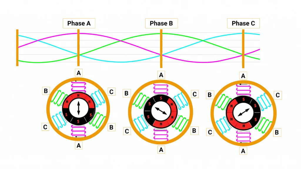
The speed of the rotating field, called synchronous speed, is fixed by just two things. It rises in direct proportion to supply frequency and falls in inverse proportion to the number of poles. The rotor of a three phase induction machine running as a motor always turns a little below this speed. How far below depends on load.
How the Number of Poles Sets Speed and Torque
More poles mean a slower field. For the same output power, a slower shaft must deliver proportionally more torque. That is why low-speed, many-pole motors are larger and heavier for a given power rating.
| Poles | Synchronous speed at 50 Hz (rpm) | Synchronous speed at 60 Hz (rpm) |
| 2 | 3,000 | 3,600 |
| 4 | 1,500 | 1,800 |
| 6 | 1,000 | 1,200 |
| 8 | 750 | 900 |
| 10 | 600 | 720 |
| 12 | 500 | 600 |
Two-pole and four-pole motors dominate the market. They give the most power from a given frame and the lowest cost per kilowatt, and pumps and fans are designed around these speeds. Six- and eight-pole motors are used for slower direct-drive loads.
Pole-changing motors, such as the Dahlander (consequent-pole) connection, reconnect a single winding to give two speeds in a 2:1 ratio, for example 1,500 and 750 rpm at 50 Hz. This gives two-speed operation without electronics.
What Is Slip and Why Is It Never Zero?
Slip is how far the rotor lags the field, expressed as a fraction or percentage of synchronous speed. If the rotor ever reached synchronous speed, the field would no longer move relative to the bars. No voltage would be induced, no current would flow, and there would be no torque. Friction alone would then slow the rotor down. So a three phase induction motor always runs with some slip.
Slip increases with load. At no load it is a fraction of a percent. As shaft torque rises, the rotor slows a little, the bars cut the field faster, and more current and torque result.
The frequency of the rotor currents equals slip times supply frequency. It is close to line frequency at standstill and only a hertz or two at full load.
Full-load slip depends on size and design. NEMA MG 1 caps Designs A, B and C below 5%, and Design B data span about 0.5–5%. Large, efficient machines often run below 1%. Fractional-kilowatt motors sit at the top of the range or above it. NEMA Design D motors deliberately run at about 5–13%.
Worked example: a 4-pole 3 phase induction motor on a 50 Hz supply has a synchronous speed of 1,500 rpm. If its nameplate full-load speed is 1,450 rpm, the rotor lags by 50 rpm. Fifty is one-thirtieth of 1,500, so the slip is about 3.3%. The rotor currents then alternate at about 3.3% of 50 Hz, or roughly 1.7 Hz.
Torque-Speed Characteristic of a Three Phase Induction Motor
The torque-speed curve is the most useful single picture of a three phase induction motor. Read it from standstill to synchronous speed:
- Locked-rotor (starting) torque: the torque at zero speed. For a NEMA Design B motor it is typically well above full-load torque; the standard range is about 70–275% depending on size and poles.
- Pull-up torque: the lowest point of the curve during acceleration. It must stay above load torque the whole way up, or the motor will hang at low speed.
- Breakdown (pull-out) torque: the peak of the curve, typically about 175–300% of full-load torque for Design B. If load torque exceeds it, the motor stalls.
- Stable operating region: between breakdown and synchronous speed the curve is steep and almost straight. Torque rises roughly in proportion to slip, so a small speed drop gives a large torque increase. This is why induction motors hold speed well.
Beyond normal motoring, the curve continues in both directions. Below zero speed, with the rotor turned against the field, is the braking (plugging) region. Swapping two phases on a running motor puts it here, and it stops quickly at the cost of heavy rotor heating. Above synchronous speed, torque reverses and the three phase induction machine enters the generating region, returning power to the supply.
Rotor resistance shapes the curve. Raising it moves breakdown torque toward standstill without changing its peak value. This is exactly what wound-rotor resistors and deep-bar or Design D cages exploit to get high starting torque.
The operating point is wherever the motor curve crosses the load curve:
- Centrifugal fans and pumps need little torque at low speed, with torque rising roughly with the square of speed. Almost any design accelerates them easily.
- Constant-torque loads such as conveyors, positive-displacement pumps and extruders need full torque from standstill. These need enough locked-rotor and pull-up torque margin.
The trade-off is fundamental. In a standard cage 3 phase induction machine, high starting current comes with modest starting torque. Designs that raise starting torque by adding rotor resistance pay for it in running slip and efficiency.
Losses, Power Flow and Efficiency of a 3 Phase AC Induction Motor
Follow the power through a 3 phase AC induction motor:
- Electrical input enters the stator.
- Stator copper loss is the heating in the stator winding resistance.
- Core loss is hysteresis and eddy-current loss in the laminations, mostly in the stator.
- What remains crosses the gap as air-gap power.
- Rotor copper loss takes a slice of the air-gap power equal to the slip fraction. At 3% slip, 3% of the air-gap power heats the rotor. This is why low slip and high efficiency go together.
- The rest becomes mechanical power, from which friction and windage (bearings and fan) and stray load losses (harmonic and leakage-flux effects) are subtracted.
- What is left is shaft output.
Engineering lecture material gives an average loss distribution for NEMA Design B motors:
| Loss component | Share of total losses |
| Stator copper | 37% |
| Core (iron) | 20% |
| Rotor copper | 18% |
| Stray load | 16% |
| Friction and windage | 9% |
The proportions shift with rating and efficiency class. For a specific machine, measure them rather than assuming them.
Efficiency rises with size. IEC 60034-30-1 sets minimum nominal efficiencies for each IE class. For 4-pole, 50 Hz motors:
| Rated output | IE3 minimum | IE4 minimum |
| 0.75 kW | 82.5% | 85.7% |
| 7.5 kW | 90.4% | 92.6% |
| 75 kW | 95.0% | 96.0% |
The second edition of IEC 60034-30-1, published in 2025, formally added IE5 (ultra-premium efficiency).The scheme now runs from IE1 to IE5.Regional minimum energy performance standards are built on these classes. In the European Union, three-phase motors from 0.75 kW to 1,000 kW must meet at least IE3.Since July 2023, 2-, 4- and 6-pole motors from 75 kW to 200 kW must meet IE4.North American rules use broadly comparable premium-efficiency levels tabulated in NEMA MG 1.
Part-load behavior matters as much as the nameplate. According to the U.S. Department of Energy fact sheet “Determining Electric Motor Load and Efficiency”, most electric motors are designed to run at 50–100% of rated load. Peak efficiency is usually near 75% load, and efficiency falls off sharply below about 50% load. Power factor drops earlier and more gradually as load falls, because the magnetizing current stays almost constant while the useful current shrinks. A typical induction motor runs at a power factor of about 0.8–0.9 at full load but only about 0.2–0.3 at very light load.Oversized, lightly loaded motors therefore waste energy and draw reactive current.
Starting Methods for 3 Phase Induction Motors
At standstill the motor looks like a transformer with its secondary short-circuited. Only the winding resistance and leakage reactance limit the current, and there is no back-EMF from rotation. A direct-on-line start therefore typically draws about six to eight times full-load current. That inrush causes voltage dips that can flicker lights, trip undervoltage relays and upset other loads on a weak supply
The governing rule of thumb is that starting current falls roughly in proportion to applied voltage, but starting torque falls roughly with the square of voltage. Halving the voltage halves the current but leaves only about a quarter of the torque.
| Method | Starting current (vs DOL) | Starting torque (vs DOL) | Notes |
| Direct-on-line (DOL) | 100% (about 6–8× full-load) | 100% | Simplest and cheapest; full mechanical and electrical shock |
| Star-delta | About one-third | About one-third | Motor must be delta-rated for line voltage; transition transient; light-start loads only |
| Autotransformer | Reduced roughly with the square of the tap (e.g., 50/65/80% taps) | Reduced with the square of the tap | Best torque per line amp of the voltage-reduction methods; bulky |
| Soft starter | Adjustable, typically 2–5× full-load | Adjustable, falls with voltage squared | Smooth ramp; no speed control; still a reduced-voltage method |
| Variable-frequency drive (VFD) | Near rated current | Up to rated torque or more from zero speed | Best start; adds speed control and cost |
| Rotor resistance (wound rotor) | Low | High, up to breakdown torque | Only for slip-ring motors |
Speed Control of Three Phase Induction Motors
Before power electronics, there were three classic speed-control methods:
- Pole changing: discrete speeds only.
- Rotor resistance (wound rotor): smooth control, but slip power is wasted as heat.
- Stator voltage control: limited range and high rotor losses, so it is only practical for fan loads.
Modern three phase induction motors are driven by inverter test :
- V/f (volts-per-hertz) control raises voltage in proportion to frequency. This keeps the air-gap flux roughly constant, so full torque is available across the speed range. It is simple, robust and ideal for pumps and fans.
- Field-oriented control (FOC) splits the stator current into a flux-producing part and a torque-producing part and controls each separately. This gives the induction motor DC-machine-like dynamic response.
- Sensorless control estimates rotor speed and flux from terminal voltages and currents, so no encoder is needed.
- Direct torque control (DTC) selects inverter switching states directly from torque and flux errors. It gives very fast torque response.
- Field weakening applies above base speed. The inverter’s voltage limit is reached, so frequency rises while voltage stays fixed and flux falls. The result is a constant-power region, where available torque falls as speed rises.
- Regenerative braking drives the machine slightly above the field speed. Power then flows back to the DC link and is absorbed by a braking resistor or returned to the grid or battery by an active front end.
Inverter drives are the reason the induction motor now handles variable-speed duty that once belonged to DC machines, from machine tools to traction.
Advantages and Disadvantages of 3 Phase Induction Motors
| Advantages | Disadvantages |
| Rugged, simple construction with no brushes (cage rotor) | High inrush current on direct-on-line start |
| Low cost per kilowatt; mature global supply chain | Lagging power factor, poor at light load |
| Self-starting on a three-phase supply | Speed fixed by line frequency without a drive |
| Near maintenance-free; tolerates harsh environments | Rotor copper loss lowers efficiency versus magnet machines |
| No permanent magnets; no rare-earth supply risk | Starting torque and efficiency trade off in fixed-cage designs |
| Can run as a generator; good overload capacity up to breakdown torque | Efficiency and power factor drop when oversized or lightly loaded |
A variable-frequency drive removes most of the classic drawbacks. It eliminates inrush, gives full torque from zero speed, makes speed adjustable and decouples power factor at the grid from the motor. But it adds cost, harmonic currents on the supply side, fast voltage edges that stress winding insulation and bearings, and a control system that needs proper validation.
Applications of Three Phase Induction Motors
- Centrifugal duty: pumps, fans, blowers, compressors, HVAC. Load torque is low at low speed, so a standard three phase induction motor starts them easily. VFDs cut energy use sharply at reduced flow because power demand falls steeply with speed.
- Constant-torque duty: conveyors, mixers, extruders, machine tools. The steep stable region holds speed under load. Vector-controlled drives give accurate torque down to standstill.
- Heavy-start duty: crushers, mills, hoists, cranes, punch presses. High-slip cage designs or wound-rotor motors provide high locked-rotor torque and ride through load shocks. Hoists also use the regenerative region when lowering loads.
- Traction: electric vehicles and rail. The rotor of a 3 phase AC induction motor has no magnets, so there is no rare-earth exposure and no magnet demagnetization risk. Its robustness at high speed and wide field-weakening range suit traction inverter test.
- Generation: wind and small hydro. Cage induction generators serve fixed-speed and small installations. Doubly fed induction generators account for roughly half of the wind power generation system market, according to one U.S. patent, because the rotor converter only needs to handle the slip power.
Three Phase Induction Motor vs Other Motor Types
| Motor type | Rotor, efficiency and cost | Control and typical use |
| Three phase induction motor | Induced rotor current; good efficiency, limited by rotor copper loss and magnetizing current; low cost, no magnets | Self-starts on the grid, VFD for variable speed; general industry, pumps, fans, some traction |
| Permanent magnet synchronous (PMSM) | Permanent magnets; highest efficiency at most operating points and compact; higher cost, often rare-earth magnets | Needs an inverter (except line-start variants); EV traction, servo, high-efficiency drives |
| Wound-field synchronous | DC field winding; high efficiency with adjustable power factor; higher cost from the exciter and brushes or a brushless exciter | Needs a starting cage or inverter; large compressors, mills, generators |
| Brushed DC | Field winding or magnets plus commutator; moderate efficiency; commutator and brush maintenance | Simple speed control from DC; legacy drives, small actuators |
| Switched reluctance (SRM) | Salient iron rotor with no excitation; good efficiency, but torque ripple and noise are challenges; very low cost, no magnets or rotor windings | Needs a dedicated converter and control; niche traction, appliances, harsh environments |
In EV traction, the choice comes down to priorities. Some designs use a three phase induction motor because it avoids rare-earth magnets and their supply risk. When it is de-energized there is no permanent-magnet field, so a coasting secondary-axle motor adds almost no electromagnetic drag. Bearing, gear and windage losses remain. Other designs pick a PMSM for its higher efficiency at the light-load, mid-speed points that dominate real driving cycles, and for its higher power density. The two are often combined: a widely analyzed dual-motor architecture pairs a permanent-magnet machine on the rear axle, which does most of the work, with a front-axle induction machine that adds power or regenerative braking when needed and simply free-spins when idle.
How Three Phase Induction Motors and Their Drives Are Tested
Motor testing starts with characterizing the 3 phase induction machine itself:
- No-load test: the motor runs uncoupled at rated voltage and frequency. Because slip is almost zero, the input power is mostly core loss plus friction and windage, and the current is mostly magnetizing current. This gives the magnetizing branch of the equivalent circuit.
- Locked-rotor test: the rotor is blocked and a reduced voltage is applied to drive about rated current. With slip at 100%, the magnetizing branch carries little current. Input power and current then reveal the winding resistances and leakage reactances. Together with a DC stator resistance measurement, the two tests give a working equivalent circuit.
- Load test on a dynamometer: the motor is loaded at several points while input power, torque and speed are measured. This gives efficiency, power factor and slip. Under IEEE 112 and IEC 60034-2-1, the most accurate methods separate the losses: they measure stator and rotor copper, core, friction and windage, and derive stray load loss from the remaining loss.
- Temperature-rise (heat-run) test: the motor runs at rated load until it reaches thermal equilibrium, which confirms that winding temperature stays within its insulation class. The IEC 60034 series covers rating, efficiency testing, starting performance (Part 12) and efficiency classes (Part 30-1).
Validating the drive is a separate problem. The traditional approach is a real motor coupled to a dynamometer. This is realistic, but it is slow to reconfigure, mechanically limited and risky to push into faults. Shorting a phase, losing an encoder or overspeeding a rotor on purpose can destroy hardware.
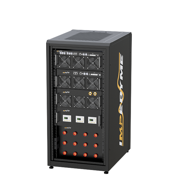
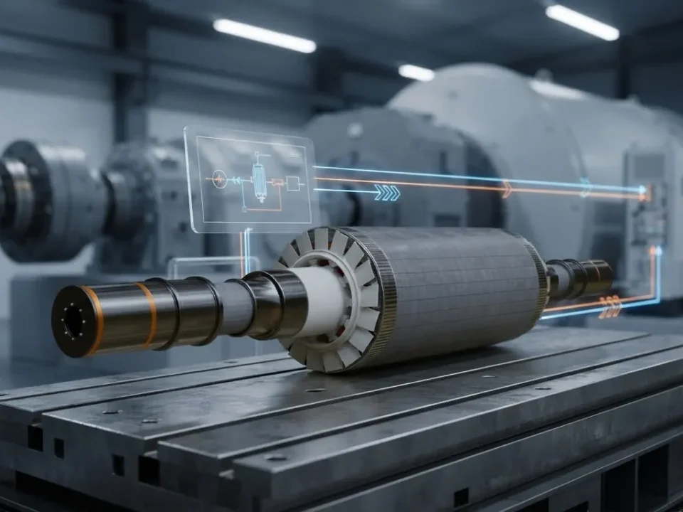
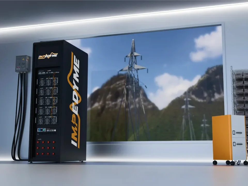
A Power Hardware in the Loop (P-HIL) motor emulator takes another route. It is a regenerative power converter controlled by a real-time induction machine model. It measures the voltages that the inverter under test applies to its terminals, solves the machine model in real time, and forces the matching currents back into the inverter.To the inverter it looks electrically like a spinning three phase induction machine, but nothing rotates.This lets teams:
- inject faults safely
- sweep extreme parameters such as rotor resistance, saturation and inertia
- switch between motor variants in software
- run repeatable regression tests at full power
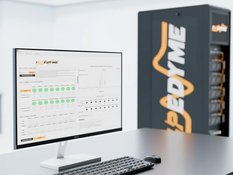
Impedyme’s motor emulator run induction machine (alongside PMSM and BLDC) models on an FPGA-based real-time platform with model time steps as low as 90 ns. They operate in four-quadrant, regenerative mode, with programmable fault injection that includes phase short circuits, open-phase faults and sensor failures.
Conclusion
A three phase induction motor is an asynchronous machine whose rotor current is induced rather than supplied, and it can also run as a generator. A 3 phase induction motor starts by itself because the three-phase stator creates a rotating field that cuts the stationary rotor and produces torque immediately. It always runs at some slip below synchronous speed, and the torque-speed curve, from locked-rotor through pull-up to breakdown torque, sets where it operates against any load. Its efficiency is governed by a predictable chain of losses and graded by IE classes, while inverter drives have turned the 3 phase AC induction motor into a precise variable-speed machine. Characterizing the three phase induction machine and validating its drive, on a dynamometer or a P-HIL emulator, are what turn those principles into reliable products.