overcurrent protection card

Application knowledgeGridMotorProduct knowledge

overcurrent protection header

Overcurrent Protection


Overcurrent protection detects current above the rating of a conductor or component and interrupts it before the released energy damages insulation, semiconductors or people. Every overcurrent protection device, from a fuse or breaker to an overcurrent relay, has to sense, decide and interrupt within the withstand limit of the weakest element in the circuit. This guide explains how each over current protection device works and how overload protection devices differ from short-circuit protection. It then covers phase overcurrent protection and overcurrent relay settings, sizing against maximum overcurrent protection ratings, transformer overcurrent protection, and overcurrent protection circuit design inside converters. It ends with the step most guides leave out: proving the scheme works before it meets a real fault.

What Is Overcurrent Protection?

Overcurrent is any current greater than a conductor’s ampacity or a piece of equipment’s continuous or short-time withstand rating, whatever the cause. Overcurrent protection is the function that detects it and interrupts it within the thermal and mechanical withstand of the weakest element in the current path.

Every scheme works in three stages:

  1. Sense. A bimetal, fuse element, current transformer, shunt or Hall sensor measures the current.
  2. Decide. The measured magnitude and duration are compared with a characteristic.
  3. Interrupt. An element melts, contacts open, or a semiconductor turns off.

All three stages together must finish inside the withstand limit of the weakest component. That component is often a cable termination, a busbar support or a semiconductor die, not the device the designer was focused on.

Three different jobs are routinely confused:

  • Conductor protection keeps insulation below its temperature limit.
  • Equipment protection limits damage to transformers, motor emulator and converters, each of which has its own withstand curve.
  • Personnel protection guards against shock and arc flash. It usually needs residual-current detection or very fast clearing, which a device sized for the conductor cannot provide.

Core vocabulary:

  • OCPD (overcurrent protective device): a fuse, circuit breaker, relay-plus-breaker combination or electronic switch that performs the overcurrent protection function.
  • Ampacity: the continuous current a conductor can carry under stated installation conditions without exceeding its temperature rating.
  • Pickup: the lowest current at which a device starts to operate.
  • Interrupting (breaking) rating: the highest prospective fault current the device can safely interrupt at rated voltage.
  • Clearing time: the time from fault inception to final current zero, arcing included.
  • Let-through I²t: the current-squared-time energy passed downstream while the device clears.
  • Time–current characteristic: the curve linking current magnitude to operating time.

During a short fault, conductor heating is adiabatic: there is no time for heat to escape. The energy a conductor can absorb before reaching its limiting temperature therefore rises with the square of its cross-sectional area, multiplied by a material constant that reflects conductor metal, insulation type and start and end temperatures. Damage follows energy, not instantaneous current. A very high peak that lasts a few milliseconds can be harmless, while a modest fault that lasts two seconds can destroy the same cable.

What Causes Overcurrent Conditions?

ConditionMagnitude and time to damageConsequences and typical causes
OverloadAbout 1.05–6× rating; damage over seconds to hoursCumulative heating, with insulation life roughly halving for every 10 °C of sustained rise. Caused by load aggregation, motor overload, or a stalled or locked rotor.
Short circuitSet by source impedance, often tens of kA; damage in millisecondsElectromagnetic forces and arc-flash energy. Caused by insulation breakdown, mechanical damage, moisture ingress or converter shoot-through.
Ground faultMilliamps up to full fault level, depending on grounding; damage in milliseconds to secondsShock hazard and fire. Caused by insulation failure to the enclosure, damaged cords or water.
Arc faultOften near or below load current and erratic; seconds to ignitionFire. Caused by loose terminations, crushed conductors or carbon tracking.

Short circuits. When a short circuit starts near voltage zero in an inductive circuit, a decaying DC offset adds to the symmetrical current. The first peak can then approach twice the symmetrical peak, and that first peak sets the mechanical forces and the breaker’s making duty. Any overcurrent protection device installed at that point must be rated for this asymmetrical peak, not just the symmetrical value.

Ground faults. These are current flowing outside the intended path. They are detected residually: the vector sum of the phase and neutral currents is zero unless some current returns by another route. This is why ground-fault elements sit alongside phase overcurrent protection rather than replacing it.

Arc faults. These are the blind spot of conventional overcurrent protection. A series arc at a loose terminal draws less current than the load itself. A parallel arc sputters in half-cycle bursts that a thermal element averages away and that never stay above an instantaneous threshold long enough to trip it. The arc’s signature is in its high-frequency content and irregular conduction, not its magnitude.

Legitimate transients. Several events are not faults but still must be ridden through: motor starting, locked-rotor tests, and inrush when capacitors or transformers are energized. Every overcurrent relay setting balances riding through these against tripping on real faults.

Overcurrent Protection vs Overload Protection Devices: Are They the Same?

No. Overload protection is the thermal subset of overcurrent protection; short-circuit protection is the other subset. Overload protection devices, such as thermal or electronic motor overload relays, model how the protected equipment heats up but have little or no ability to interrupt a fault. A motor overload relay only opens the contactor coil circuit. The contactor itself is rated to make and break locked-rotor current, not tens of kiloamps.

This is why IEC 60947-4-1 defines how a starter coordinates with its short-circuit protective device (SCPD):

  • Type 1 coordination: the contactor and overload relay may be damaged by a short circuit, provided nobody is endangered.
  • Type 2 coordination: only light, easily separated contact welding is allowed, and the starter stays serviceable. 

Each part of the combination has one job. The contactor switches the load, the overload relay protects the motor against sustained overcurrent, and the fuse or breaker clears short circuits.

Types of Overcurrent Protection Devices Compared

Selecting an overcurrent protection device comes down to four questions:

  1. How fast is it at the fault level that matters?
  2. Is its interrupting rating above the available fault current?
  3. Can it be reset, and how much maintenance does it need?
  4. How accurate and repeatable are its settings?

Over current protection deviceSpeed and interrupting capabilityReset, setting accuracy and typical use
Current-limiting fuseClears in under half a cycle; very high interrupting capability, commonly 100 kA or moreMust be replaced after operating. Fixed setting that can drift with ageing. Used at high fault levels and for semiconductors.
Thermal-magnetic breakerOne to a few cycles; interrupts up to its kA ratingResettable. Wide tolerance and ambient-sensitive. Used for branch and building circuits.
Electronic-trip breakerOne to a few cycles, adjustable; interrupts up to its kA ratingResettable. Tight, repeatable settings. Used for feeders and selective systems.
Relay plus breakerRelay time plus 3–5 cycles of breaker time; interrupting capability set by the breakerResettable. Precise, programmable settings. Used for medium voltage, large low-voltage systems and transformers.
Solid-state breaker / e-fuseMicroseconds; interrupting capability limited by the semiconductorReset electronically. Precise settings. Used for DC systems, converters and batteries.

Fuses: How Does This Over Current Protection Device Work?

Operation. A fuse element is a metal strip with notches: narrowed sections where resistive heating concentrates. Total clearing time is the pre-arcing (melting) time plus the arcing time. The arc lengthens across the notches and is quenched in silica sand filler, which absorbs its energy.

Current limitation. In its current-limiting range, a fuse melts within the first quarter-cycle and clears before the prospective first peak. One published peak let-through characteristic for a 30 A semiconductor fuse shows the peak held to about 3.25 kA with 100 kA rms available. Compared with a device that lets the first half-cycle through, let-through I²t falls by an order of magnitude or more. No other overcurrent protection device limits energy this effectively at high fault levels.

Fuse classes:

  • Fast-acting fuses suit resistive loads and semiconductors.
  • Time-delay fuses ride through motor inrush and are widely used for transformer overcurrent protection, where they must withstand energization inrush.
  • General-purpose fuses protect cables across the full overcurrent range.
  • Semiconductor fuses (partial-range aR and full-range types) exist because IGBT and SiC modules can withstand far less I²t than a general-purpose fuse lets through. The fuse’s total clearing I²t, at the real working voltage, must stay below the module’s I²t rating.

Limitations. Elements fatigue under cyclic loading and can drift. Every operation means a replacement, and fitting a wrong-class replacement silently changes the overcurrent protection. Fast clearing also cuts arc-flash incident energy, but only when the arcing current falls inside the fuse’s current-limiting range.

Circuit Breakers: Thermal-Magnetic and Electronic Trip Units

Thermal-magnetic breakers have two elements:

  • A bimetal gives the inverse-time overload response, the same principle used in many overload protection devices. It is sensitive to ambient temperature and must be derated in hot enclosures.
  • A magnetic armature gives instantaneous tripping.

Electronic trip units measure current through internal current transformers and provide four functions, with repeatable settings that do not depend on ambient temperature:

  • Long-time (L): overload.
  • Short-time (S): delayed fault tripping, used for selectivity.
  • Instantaneous (I).
  • Ground fault (G).

Curve classes. IEC 60898-1 fixes the instantaneous trip bands for miniature breakers:

  • Type B: 3–5 times rated current.
  • Type C: 5–10 times rated current.
  • Type D: 10–20 times rated current.

North American practice describes the same idea as a fixed or adjustable instantaneous pickup, expressed as a multiple of the rating.

Interrupting ratings. These are stated in kA. IEC 60947-2 separates two values:

  • Icu (ultimate breaking capacity): the breaker interrupts the fault but may not be fit for further service.
  • Ics (service breaking capacity): stated as 25, 50, 75 or 100% of Icu; the breaker remains serviceable afterwards.

Never install a breaker where the available fault current exceeds its rating. Series ratings let a lower-rated downstream breaker be protected by a tested upstream device, but only for the exact combination that was tested and listed. A series rating cannot be created by calculation, and it usually gives up selectivity.

Overcurrent Relays: 50, 51 and Inverse-Time Phase Overcurrent Protection

An overcurrent relay separates sensing and decision from interruption. That separation is why relays dominate medium-voltage and large low-voltage systems.

The trip chain. Primary current passes through a current transformer (CT) with a 1 A or 5 A secondary. The CT feeds the overcurrent protection relay element, whose trip contact energizes the breaker trip coil, which opens the breaker. Trip-circuit supervision monitors the coil and its wiring continuously, because a relay that operates into an open trip circuit protects nothing.

ANSI device numbers that matter:

  • 50: instantaneous phase overcurrent.
  • 51: time-delayed (inverse or definite) phase overcurrent.
  • 50N/51N: residual ground overcurrent, calculated from the summed phase CTs.
  • 51G: ground overcurrent from a CT in the neutral or ground connection.
  • 46/50Q: negative-sequence overcurrent, for unbalance and phase-to-phase faults.
  • 67: directional overcurrent.

Phase overcurrent protection uses 50/51 elements on every phase to detect three-phase and phase-to-phase faults. On solidly grounded systems it also backs up ground-fault protection.

Definite-time and inverse-time elements. A definite-time over current relay trips after a fixed delay once current exceeds pickup. An inverse-time element operates faster as current rises. Pickup is set in primary amps and converted to secondary amps through the CT ratio. The time multiplier setting (TMS, in IEC terms) or time dial (in IEEE terms) moves the curve up or down.

The standard inverse curves. In the IEC 60255-151 inverse characteristic, operating time equals the TMS multiplied by a curve constant, divided by one less than the multiple of pickup raised to a curve exponent. IEEE C37.112 uses the same structure plus an added constant.

Curve (standard)Constant and exponentAdded constant
Standard inverse (A), IEC 60255-151Constant 0.14; exponent 0.02None
Very inverse (B), IEC 60255-151Constant 13.5; exponent 1None
Extremely inverse (C), IEC 60255-151Constant 80; exponent 2None
Moderately inverse, IEEE C37.112Constant 0.0515; exponent 0.020.114
Very inverse, IEEE C37.112Constant 19.61; exponent 20.491
Extremely inverse, IEEE C37.112Constant 28.2; exponent 20.1217

Worked example. A 400 A feeder has a 600:5 CT and a standard-inverse element with pickup at 500 A primary, which is 4.17 A secondary. A 3,000 A fault is 6 times pickup (25 A secondary). At that multiple the standard-inverse curve gives a base time of about 3.85 s, which the TMS then scales:

SettingOperating time at 3,000 A
Standard inverse, TMS 0.10.38 s
Standard inverse, TMS 0.31.15 s
Very inverse, TMS 0.10.27 s
Extremely inverse, TMS 0.10.23 s

Time scales linearly with TMS. The roughly 0.77 s gap between TMS 0.1 and TMS 0.3 is far more than any coordination interval requires, so in practice the upstream relay can be made faster.

Directional elements. On feeders with distributed energy resources (DER), and in ring or parallel networks, fault current can flow in either direction. A 67 element uses a voltage polarizing quantity so that it trips only for forward faults. This prevents a healthy feeder from tripping on its own backfeed into a neighbouring fault.

CT saturation. High current with DC offset, or excessive burden, saturates the CT core and collapses part of each secondary cycle. The relay then measures less current, inverse-time elements slow down, and coordination margins shrink exactly at the highest fault levels. Check the CT accuracy class and knee-point voltage against the maximum asymmetrical fault current and the real burden of the leads plus the relay.

Overcurrent Protection Circuit Design Inside Converters and Power Supplies

An overcurrent protection circuit inside a converter has to act in microseconds, far faster than any external overcurrent protection device can respond.

Current sensing options:

  • Shunts: accurate and cheap, but lossy and not isolated.
  • Hall-effect sensors: isolated, but limited in bandwidth and subject to offset.
  • Rogowski coils: wide bandwidth, but AC-only and in need of an integrator.
  • Integrated sensing: built into power modules and gate drivers.

Detection and turn-off:

  • A fast comparator trips against a reference. Leading-edge blanking masks the turn-on spike caused by diode recovery and capacitance charging, so it is not mistaken for a fault.
  • Cycle-by-cycle limiting in peak current-mode control ends each switching pulse when current reaches the limit.
  • Desaturation (DESAT) detection in IGBT and SiC gate drivers watches the on-state voltage. If the device leaves saturation while commanded on, the driver turns it off with a soft shutdown, slowing the turn-off to keep overvoltage within the device rating.

Protective components:

  • E-fuses combine a switch, a current limit and a fault timer.
  • PPTC devices trip thermally, and are slow but resettable, which makes them compact overload protection devices for low-power rails.
  • Solid-state circuit breakers interrupt DC in microseconds without an arc, making them a fully electronic over current protection device.

Fault-response policies:

  • Constant-current limiting holds current at the limit. It suits chargers and bench supplies, where a laboratory supply crosses over from constant voltage to constant current at the set limit.
  • Foldback reduces the current limit as output voltage collapses, which cuts dissipation in linear pass devices.
  • Hiccup shuts down and retries periodically. It suits transient faults in DC/DC converters.
  • Latch-off stays off until reset. It is the right policy wherever a repeated fault is hazardous.

Why the layers are not interchangeable. A SemiEngineering technical analysis of SiC short-circuit ruggedness puts the SiC MOSFET short-circuit time and resulting power loss “in the range of 2–3 μs”, and a 2023 IET Power Electronics paper notes that gate-driver short-circuit protection for SiC MOSFETs must act “within 3 µs, while for Si IGBT it is less than 10 µs.” The fastest mechanical device needs milliseconds. The upstream breaker protects the cable; only the gate driver protects the die.

The same layered approach applies inside Impedyme real-time Hardware in the loop  platforms:

  1. Analog inputs are filtered by low-pass filters before the ADCs on an UltraScale+ FPGA/SoC.
  2. In parallel, the inputs feed hardware comparators with high (L.HIGH) and low (L.LOW) thresholds. Any violation is ORed into a fault manager.
  3. The fault manager gates the PWM outputs through AND logic, independently of the CPU running the user application.
  4. A watchdog covers a stalled real-time execution.
  5. A separate safety FPGA, with its own power supply and an interlock connector, adds a final independent layer.

Impedyme describes this as a dual-layer architecture. A configurable, time-delayed software overcurrent protection algorithm sits on top of factory-defined, non-configurable analog comparators and hardware logic gates, which act as the last line of defense.

GFCI, RCD and AFCI: Protection an Overcurrent Device Cannot Provide

A 20 A breaker will never trip on a 30 mA shock current, because overcurrent protection is sized for conductors, not people. Residual-current devices fill that gap by passing all live conductors through a core-balance CT; any imbalance means current is returning by another path.

Thresholds. Personnel protection uses 30 mA in IEC practice, and North American GFCIs trip at 4–6 mA. A general-type 30 mA RCD must trip within 300 ms at rated residual current and within 40 ms at five times rated.

RCD types:

  • Type AC detects sinusoidal AC only.
  • Type A adds pulsating DC and tolerates up to 6 mA of smooth DC.
  • Type F adds mixed-frequency residual currents and tolerates up to 10 mA of smooth DC.
  • Type B also detects smooth DC.

Type B matters for EV chargers, solar inverter test and three-phase variable frequency drives (VFDs). In that equipment a fault behind a rectifier can produce smooth DC residual current, which saturates the core of a Type A device and blinds it. IEC 62955 defines a 6 mA DC detecting device (RDC-DD) built into Mode 3 chargers, which allows Type A protection to be used upstream.

AFCIs detect arcing by analysing the current waveform’s high-frequency content and irregular conduction intervals. This lets them separate real arcs from the normal switching signatures of loads such as brushed motors and dimmers, and catch faults that never cross the pickup of a conventional over current protection device.


Time–Current Curves: How to Read and Use Them

Reading the curves. Time–current curves use log-log axes, with current on the horizontal axis and time on the vertical, because both quantities span several decades. Every overcurrent protection device plots as a band, not a line. The lower edge is the minimum melting or trip time, the upper edge is the total clearing time, and the width reflects manufacturing tolerance. Breaker curves have three regions:

  • Long-time: overload.
  • Short-time: delayed fault tripping.
  • Instantaneous: a vertical drop to the minimum clearing time.

What a coordination sheet shows. Alongside the device bands, a complete coordination sheet plots:

  • The conductor damage curve.
  • The transformer through-fault damage curve and its inrush point, the two limits that bound transformer overcurrent protection.
  • The motor starting curve and locked-rotor point.
  • A vertical line at the maximum available fault current, where every curve ends.

Acceptance test. Each band must sit below and to the left of every damage curve it protects. It must also sit above and to the right of every legitimate inrush or starting point. For devices in series, the downstream band must lie entirely below and to the left of the upstream band, with a time margin between them.

Worked reading. Take a 1,000 kVA, 13.8 kV/480 V transformer with 5.75% impedance:

  • Ratings. Primary full-load current is about 42 A. Taking the inrush point at 12 times for 0.1 s gives about 500 A at 0.1 s.
  • Damage curve. On an infinite bus, the maximum through-fault current is about 17 times rating, or about 730 A primary. The IEEE C57.109 frequent-fault curve puts that point at 2 s.
  • Relay setting. A primary overcurrent relay with 63 A pickup, standard inverse at TMS 0.2, operates in about 0.66 s at 500 A and about 0.56 s at 730 A.
  • Result. The band clears the inrush point and stays about 1.4 s below the damage curve.

How to Size and Set Overcurrent Protection, and What Maximum Overcurrent Protection Means

Step 1: Load. Under the North American convention, a continuous load (three hours or more) needs a device rated at no less than 125% of the continuous load plus 100% of the non-continuous load, unless the assembly is listed for 100% duty. IEC 60364-4-43 sets two conditions:

  • The circuit’s design current must not exceed the device’s rated current, and the rated current must not exceed the conductor’s current-carrying capacity.
  • The current that ensures the device operates within its conventional time must not exceed 1.45 times the conductor’s capacity.

That conventional current is 1.45 times rating for IEC 60898 breakers and 1.3 times for IEC 60947-2 breakers, so for breakers the second condition is met automatically. For general-purpose fuses it is about 1.6 times rating, so a fuse needs more margin to the cable.

Step 2: Correct ampacity for ambient temperature and grouping.

Step 3: Calculate available fault current, and choose an interrupting rating with margin for future source changes.

Step 4: Confirm clearing before conductor damage at both maximum and minimum fault current. The minimum case is the one usually forgotten in overcurrent protection studies. Long cables, impedance-grounded systems, and generator- or inverter-fed sources can leave the fault current below the instantaneous pickup. The device then falls into its long-time region and may take seconds to trip, or never trip.

Step 5: Translate the results into settings: pickup, curve and time dial for an overcurrent protection relay, or L-S-I settings for a breaker.

End-to-end example (400 V feeder, 80 A continuous load):

  • Device. Choose a 100 A device; the North American 125% rule would also require at least 100 A.
  • Conductor. A 50 mm² copper PVC cable with a tabulated capacity of 160 A, derated by 0.87 for ambient and 0.80 for grouping, carries about 111 A, which is above the 100 A requirement.
  • Interrupting rating. Available fault current is 25 kA, so select a 36 kA breaker.
  • Short-circuit withstand. The conductor can absorb about 33 million A²s, which at 25 kA is about 53 ms. The breaker’s let-through I²t must stay below that figure.
  • Minimum fault. The fault at the remote end is 1.8 kA, so set the instantaneous pickup at 1.5 kA (15 times rating) so the minimum fault still clears instantaneously.
  • Settings. Long-time pickup 100 A; short-time pickup 600 A with a 0.1 s delay, for selectivity with downstream breakers.

Maximum overcurrent protection on nameplates. HVAC units, inverters and combiner boxes often state “maximum overcurrent protection” (MOCP) or “maximum overcurrent protective device rating”. This is the largest fuse or breaker the manufacturer’s listing permits, based on the withstand of the equipment’s internal conductors and components. It is a ceiling, not a recommended size. HVAC nameplates pair it with a minimum circuit ampacity, and the device chosen must fall between the two values and be of the type specified.

Selectivity and Coordination: Tripping Only the Right Device

Selectivity means that the overcurrent protection device closest to the fault clears it while upstream devices stay closed. There are four main ways to achieve it:

  • Time grading. Keep a coordination time interval (CTI) between successive overcurrent relay curves at the maximum fault current both relays see. Typical values are 0.3–0.4 s for electromechanical relays, which must allow for disc overtravel, and 0.2–0.3 s for numerical relays.
  • Current grading. Use the difference in fault levels where impedance separates the devices, for example across a transformer.
  • Energy (I²t) selectivity for fuses. The upstream fuse’s pre-arcing I²t must exceed the downstream fuse’s total clearing I²t. Fuses of the same family typically achieve this at about a 2:1 rating ratio.
  • Zone-selective interlocking. A downstream device that sees the fault sends a restraint signal upstream. An upstream device that receives no restraint trips with minimal delay, giving fast bus-fault clearing without losing selectivity.

The cost of selectivity. Every added time step raises arc-flash incident energy at upstream buses. Maintenance-mode switches address this by temporarily enabling low instantaneous pickups while people are working on the equipment. Full selectivity is sometimes impossible, so document the compromise and the residual risk.

Transformer Overcurrent Protection

Transformer overcurrent protection has to fit a band between magnetizing inrush and the transformer’s damage curve.

Inrush. Magnetizing inrush typically peaks at 8–12 times rated current and decays over roughly 0.1 s to a few seconds, depending on transformer size and residual flux. It is rich in second harmonic, and differential relays traditionally restrain on the second-harmonic ratio: one published relay application note uses a 15% default threshold, and the paper “Practical Experience in Setting Transformer Differential Inrush Restraint” describes a 20% second-harmonic ratio as “the historical setting.” Low-loss modern cores can produce less second harmonic, which weakens that restraint.

Damage curves. IEEE C57.109 defines through-fault duration curves for four size categories. Categories II and III add a mechanical-duty curve for transformers that see frequent through-faults. The protection band must sit below the applicable damage curve and above the inrush point.

Maximum ratings. For transformers of 1000 V and below, NEC Table 450.3(B) limits:

  • Primary-only protection: up to 125% of rated primary current (167% below 9 A; 300% below 2 A).
  • Primary and secondary protection: up to 250% on the primary, and 125% on the secondary (167% below 9 A).

Table 450.3(A) covers transformers above 1000 V. For example, at 6% impedance or less, it allows primary fuses up to 300% and primary breakers up to 600%. 

Delta-wye transformers. A phase-to-phase fault on the secondary appears on the delta primary as 1.0 per unit in one line, against 0.866 per unit on the secondary side, so coordination margins must be checked for that case. A secondary ground fault reaches the primary at about 58% of its per-unit value, and zero-sequence current does not pass through the delta. Primary ground elements therefore cannot see secondary ground faults.

Differential protection. Differential protection (87T) is the primary protection for internal faults, with overcurrent as backup. Overcurrent alone cannot protect a transformer against internal winding faults: a turn-to-turn fault may raise the terminal current only slightly.

Motor, Drive, Battery and Inverter-Dominated Systems

Motors. Starting current is typically 6–8 times full-load amps (FLA) for several seconds, and a locked rotor draws that current indefinitely.

  • Short-circuit protection is set well above the starting current.
  • Overload trip classes for motor overload protection devices under IEC 60947-4-1 are tested at 7.2 times the setting: Class 10 trips in 4–10 s, Class 20 in 6–20 s, and Class 30 in 9–30 s.
  • Service factor. A service factor of 1.15 or more allows the overload setting to rise from 115% to 125% of FLA.
  • The arrangement is the contactor, overload relay and SCPD combination described earlier.

Drives. The drive’s own electronic current limit acts first, within microseconds. Input fuses protect the rectifier and the supply cabling. Conventional overcurrent devices on the drive output are ineffective because output frequency varies and the drive limits current first, so motor overload protection comes from the drive’s electronic thermal model.

Battery and DC systems. DC has no natural current zero, so every device must be DC-rated.

  • Prospective fault current is set by internal resistance and can reach many kiloamps.
  • Contactors may weld if asked to break currents beyond their capability.
  • Pyrofuses, often triggered by the battery management system (BMS), and solid-state DC breakers separate the circuit in under a millisecond.

Inverter-dominated systems. A 2019 CIGRE-US Grid of the Future paper on the impact of inverter-based systems on grid protection notes that inverter-based resources “generally produce low fault current between 1.1 to 1.5 times the rated output current of the inverter.” Phase overcurrent protection pickups set above load current may therefore never operate. Fault current also barely changes with fault location, which defeats time grading. The alternatives are:

  • Voltage-based elements, including voltage-restrained overcurrent.
  • Differential protection.
  • Negative-sequence elements.
  • Communications-assisted schemes.

Standards That Govern Overcurrent Protection

GroupStandards
Installation rulesNFPA 70 (NEC) Articles 240, 430 and 450; IEC 60364-4-43
Device construction and ratingsIEC 60269 and UL 248 (fuses); IEC 60898-1; IEC 60947-2; UL 489; IEC 60947-4-1
Relay characteristics and testingIEC 60255-151; IEEE C37.112; IEEE C37.2 (device numbers); IEEE C37.90
Transformer protectionIEEE C57.109; IEEE C37.91
Coordination and incident energyIEEE 242; IEEE 1584; NFPA 70E
Residual-current and arc-fault devicesIEC 61008-1; IEC 61009-1; IEC 62423; IEC 62955; UL 943; UL 1699

Editions and clause numbers change, so always confirm the edition adopted in your jurisdiction.

How Overcurrent Protection Is Tested and Validated

Each rung of the validation ladder catches errors the rung below cannot:

RungWhat it provesWhat it cannot reveal
1. Secondary injectionPickup, timing against the curve, reset ratio, trip contactsCT ratio errors, polarity, wiring
2. Primary injectionReal current through the CT and the full trip chain; wiring and polaritySource dynamics; it is still open-loop
3. Breaker timing and contact resistanceMechanical opening time, contact healthRelay logic
4. Closed-loop PHIL fault emulationReal fault waveforms with DC offset, CT saturation effects, inverter-limited contribution, post-fault recoveryCertified interrupting ratings

Validating an Overcurrent Protection Relay or Converter in Closed Loop

In closed-loop Power hardware in the loop testing, a real-time network model drives a four-quadrant power amplifier. The amplifier reproduces the fault waveform into the over current relay or converter under test, and the measured current is fed back into the model.

Open-loop injection plays a precomputed waveform no matter what the device does, and that is its blind spot. In reality a converter’s current limiter changes the current, the changed current alters the network voltage, and the altered voltage changes how the limiter responds. Only closing the loop shows whether the converter’s limiter and the upstream protection cooperate. It shows, for example, whether an inverter holding 1.2 per unit leaves the feeder’s phase overcurrent protection unable to pick up, or whether a ride-through sequence triggers a re-trip.

Recommended test matrix:

TestPointsPass criterion
Pickup accuracyRamp from 90% to 110% of settingWithin declared tolerance
Timing2×, 5× and 10× pickupWithin the curve’s tolerance class
Minimum operating currentMinimum fault caseOperates
Instantaneous threshold0.9× and 1.1× settingDoes not operate / operates
Reset ratioRamp downMeets declared ratio
Directional polarityForward and reverse faultsTrips for forward faults only
Harmonic restraintInrush with a second-harmonic sweepBlocks and releases at the setting
Repeatability10 or more repeatsSpread within tolerance

Where emulators fit. A grid emulator with a programmable source impedance reproduces both stiff and weak sources. A battery emulator lets engineers apply battery-level prospective fault scenarios without staging real cells. A PHIL amplifier runs repeatable, programmed fault profiles without a short-circuit bay.

Impedyme publishes the following figures for its platform:

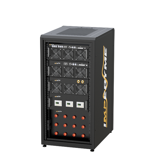
  • CHP Series: a combined HIL and PHIL platform with a regenerative power stage that sources and sinks current up to 100% of rated power. It parallels up to 550 kVA/kW, and custom configurations of 1.3 MW and above are available.
  • Grid emulator: real-time grid-impedance models (R, L, C, RL, RC and RLC). Its PHIL interface is designed for direct connection of inverters, relays and any other overcurrent protection device for closed-loop testing.
  • Real-Time Battery Emulator with BatterySim Studio: model steps as low as 90 ns and bandwidths up to 20 kHz. It scripts internal-short, over-charge and ground-fault scenarios.
  • HIL Protection application: a time-delayed overcurrent algorithm implemented in Stateflow, backed by a hardware optical overcurrent layer with a factory-defined trip threshold.

Certified interrupting-rating tests remain the job of accredited short-circuit laboratories.

Common Overcurrent Protection Problems and How to Avoid Them

ProblemSymptomRoot causeConfirming check
Nuisance trippingTrips on energization or when distorted load is runningInrush, harmonics, peak-sensing rather than true-RMS measurementWaveform capture; compare against the instantaneous setting
Underrated deviceDevice damaged or failing to clearAvailable fault current above rating; misapplied series ratingFault study against listed ratings
Lost selectivityUpstream trips on downstream faultsFault level increased after a source upgradeUpdated coordination study
CT saturationSlow or failed tripping at high currentBurden or DC offset beyond the CT’s knee pointKnee-point and burden calculation
Thermal driftSeasonal tripsAmbient effect on the bimetalMeasure enclosure temperature; derate
Fuse ageing or wrong classUnexplained opening or failure to protectElement fatigue; wrong-class replacementAudit fuse classes and ratings
Settings not reverifiedBehaviour differs from the studyUndocumented changesCompare relay files with the study
Protection blindingFeeder relay under-reachesDG infeed reducing the current seen by the relayFault study with DG modelled

Conclusion

Reliable overcurrent protection is a layered system. Overload protection devices guard against slow heating, fuses and breakers clear short circuits, and an overcurrent relay with graded phase overcurrent protection confines faults to the smallest possible zone. Inside converters, the overcurrent protection circuit must act in microseconds, before any mechanical over current protection device can respond.

Every overcurrent protection device must also stay within the maximum overcurrent protection rating on the nameplate. Transformer overcurrent protection must sit between inrush and the damage curve, and each overcurrent protection relay setting must be re-verified whenever the system changes. With Impedyme’s real-time HIL and PHIL platforms, grid emulation and battery emulation, teams can prove these settings against realistic faults in the lab before a real fault does.

Frequently Asked Questions 

What is the difference between overcurrent and overload protection?

Overload protection is the thermal subset of overcurrent protection, covering moderate, sustained overcurrent that heats equipment over seconds to hours. Overcurrent protection also includes short-circuit protection. Overload relays usually cannot interrupt fault current, so they need a fuse or breaker as backup.

What does maximum overcurrent protection mean on a nameplate?

It is the largest fuse or breaker rating the manufacturer’s listing permits for that equipment, based on internal conductor and component withstand. It is a ceiling, not a recommended size; choose a device between the minimum circuit ampacity and this maximum.

What is phase overcurrent protection?

Phase overcurrent protection uses overcurrent elements on each phase conductor, typically ANSI 50 and 51, to detect three-phase and phase-to-phase faults. On solidly grounded systems it also backs up ground-fault protection, while separate residual or neutral elements provide sensitive ground detection.

How does transformer overcurrent protection work?

Transformer overcurrent protection sets fuses or relays so their operating band sits above magnetizing inrush and below the transformer’s through-fault damage curve. Code tables cap primary and secondary ratings. Differential protection handles internal faults, with overcurrent acting as backup.

How is an overcurrent protection device tested?

Secondary injection verifies pickup and timing, primary injection checks CTs and wiring, and breaker timing confirms mechanical operation. Closed-loop power hardware-in-the-loop testing adds realistic fault waveforms and interaction with converter current limiters, which open-loop methods cannot reproduce.