DC motor controller card

Application knowledgeGridMotorProduct knowledge

DC motor controller header

DC Motor Controller

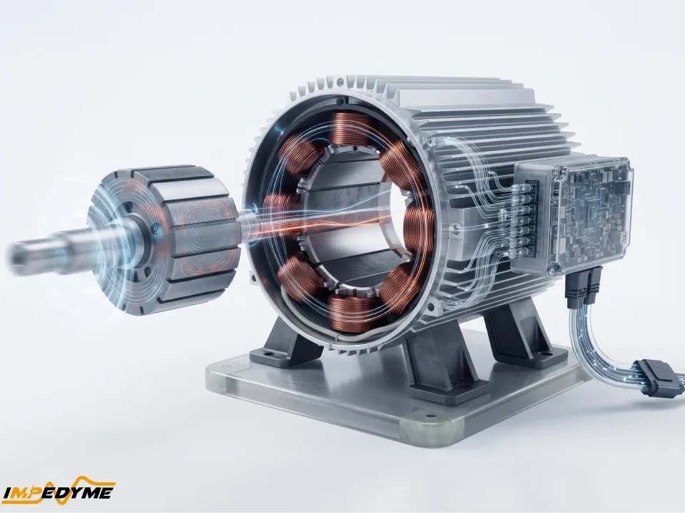
DC motor controller is the electronic device that stands between a command and a spinning shaft, and it decides almost everything about how that shaft behaves. Modern DC motor controllers regulate speed, torque, and direction, protect the motor and the power stage from faults, and hold performance steady as the load changes underneath them. The term covers an enormous range of hardware, from a single DC motor controller IC driving a small brushed motor on a hobby board to a multi-kilowatt cabinet driving an industrial servo axis. What unites them is the same underlying job: take a reference, compare it to what the motor is actually doing, and adjust the power delivered until the two agree.

This guide covers what a DC motor controller is, how a DC motor controller circuit is built block by block, the main controller types and topologies, how DC motor control differs from AC drive control, how to choose a controller for a given application, and the design challenges that catch teams late. It closes with the part almost no one covers: how to prove a controller actually works before it is ever connected to a real motor.

What Is a DC Motor Controller?

A DC motor controller is an electronic system that manages the operation of a DC motor by regulating the voltage and current delivered to it. Left connected directly to a supply, a DC motor will simply run at whatever speed the load and the supply voltage happen to produce. There is no way to slow it down, reverse it, limit its inrush current, or stop it in a controlled way. A DC motor controller adds all of that.

The core functions of any DC motor controller are consistent across power levels:

  • Start and stop the motor in a controlled manner, limiting inrush current on startup
  • Regulate speed by adjusting the effective voltage applied to the motor
  • Regulate torque by controlling the current flowing through the windings
  • Reverse direction by reversing the polarity applied to the motor
  • Protect the motor and the power stage against overcurrent, overvoltage, overtemperature, and stall
  • Report and react to faults, either by derating, disabling the output, or signalling a supervisory system

The reason DC motor control is so widely used is that DC motors respond in a predictable way to applied voltage. Speed and load torque trade off against each other along a downward-sloping curve, and raising the applied voltage shifts that whole curve upward. In practical terms, this means a DC motor can be made to hold a target speed at almost any load torque simply by adjusting the drive voltage appropriately. That predictability is what makes DC motor controllers comparatively simple to design and tune, and it is why the architecture has survived alongside far newer motor technologies.

How a DC Motor Controller Works

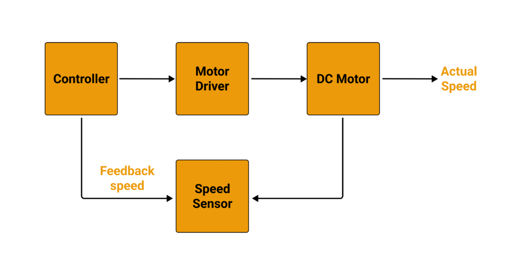
Every DC motor controller, regardless of scale, is built from the same chain of functional blocks. Understanding this chain makes both the design choices and the failure modes much easier to reason about.

Control core. A microcontroller, DSP, or FPGA holds the control algorithm. It receives the speed, torque, or position reference, compares it against measured feedback, and calculates what the output should be. On a small controller this may be a simple proportional loop running at a few kilohertz. On a high-performance axis it may be nested current, speed, and position loops running at tens of kilohertz.

Modulator. The control core’s output is a demand, not a switching pattern. The modulator translates that demand into gate signals, most commonly by pulse-width modulation. It also inserts dead time so that the upper and lower switches in a leg are never commanded on simultaneously.

Gate drivers and isolation. Logic-level signals cannot switch power devices directly. Gate drivers amplify those signals to the voltage and current the power switches need, and provide isolation between the low-voltage control domain and the high-voltage power domain.

Power switches. The switching stage does the actual work of chopping the DC supply into a controlled average. Its configuration determines whether the controller can reverse the motor, brake it, or return energy to the source.

Current and position sensing. Measured phase or armature current is what closes the torque loop and enables current limiting. Measured shaft position or speed is what closes the velocity and position loops.

Feedback loop. The comparison between reference and measurement produces an error, and the controller acts on that error continuously. This is what allows a motor to hold a constant speed while the load, temperature, and supply voltage all drift.

Protection layer. Sitting across all of the above is a set of fast protective functions: desaturation detection, overcurrent trip, DC-link overvoltage clamping, thermal derating, and watchdog supervision. On well-designed controllers, protection acts in hardware, faster than the control loop can respond.

Types of DC Motor Controllers

DC motor controllers are classified along several independent axes. A given controller sits somewhere on all of them at once, so it is more useful to understand the axes than to memorise categories.

By Motor Type

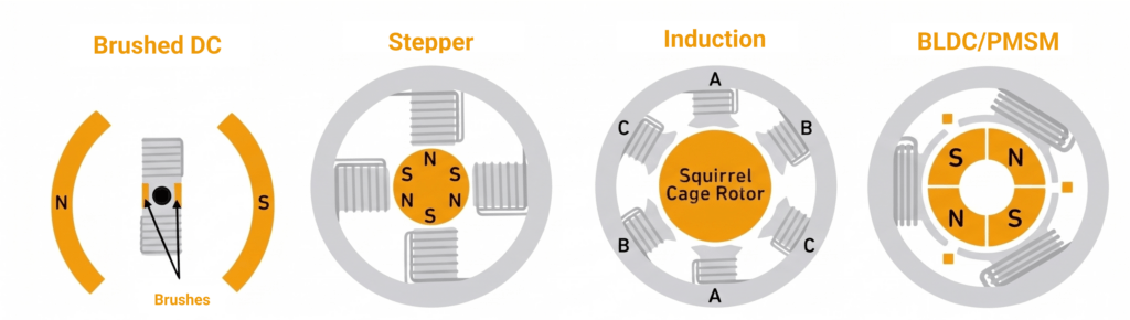
Brushed DC. The simplest case. Commutation is mechanical, handled by brushes and a commutator, so the controller only has to manage voltage magnitude and polarity.

Brushless DC (BLDC). A brushless DC motor controller must perform commutation electronically, switching current between windings based on rotor position. This adds complexity but removes the wearing parts and the electrical noise that brushes generate.

Permanent magnet synchronous (PMSM). Electrically similar to BLDC but driven with sinusoidal rather than trapezoidal currents, giving smoother torque and lower acoustic noise at the cost of a more demanding control algorithm.

Induction. Driven from an AC waveform synthesised by an inverter. Robust and inexpensive, but harder to control precisely at low speed without feedback.

Switched reluctance. No magnets and no rotor windings, making the motor extremely rugged, but the controller must manage strongly non-linear torque production and significant torque ripple.

Stepper. Driven in discrete steps by energising windings in sequence. Positioning without feedback is possible, at the cost of losing position silently if the motor stalls.

Servo. Any of the above operated in a closed position loop with a dedicated feedback device, tuned for accuracy and dynamic response rather than efficiency.

dc motor controllers

DC Motor Drive Controllers: H-Bridge, PWM, and Armature/Field Control

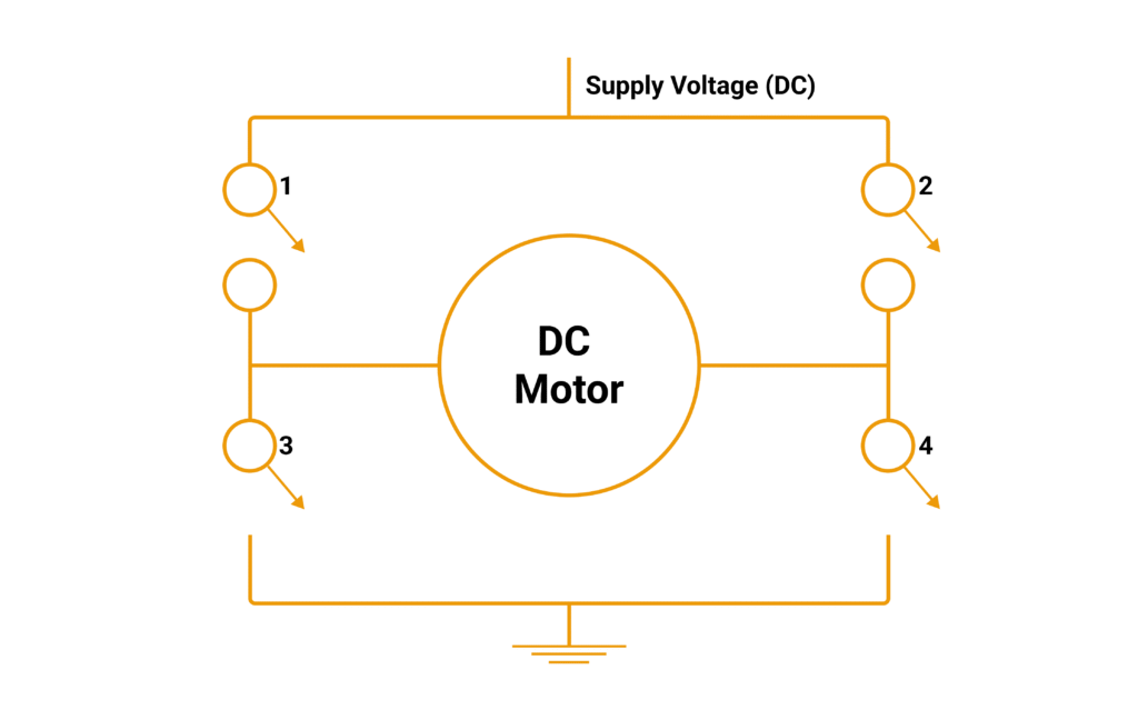
The classic DC motor controller circuit is the H-bridge: four switches arranged so that closing one diagonal pair applies the supply across the motor in one polarity, and closing the opposite pair reverses it. It is the standard approach for bidirectional brushed DC control, and it is available both as a discrete design and as an integrated DC motor controller IC. Where only one direction of rotation is required, a single switch in series with the motor is sufficient and considerably cheaper.

PWM is how speed is regulated within that topology. Rather than dissipating excess voltage, the controller switches the supply on and off rapidly and varies the proportion of time it spends on. The motor’s inductance smooths this into an effective average voltage. Because the switch is either fully on or fully off, very little energy is wasted as heat, which is why PWM has displaced older approaches almost everywhere.

Armature and field control are the legacy methods. Inserting variable resistance in the armature circuit reduces current and slows the motor; weakening the field circuit raises speed above base speed. Both work, and field weakening remains genuinely useful for extending the high-speed range of a wound-field machine. Resistive armature control, however, wastes the difference as heat and is now confined to simple or cost-driven designs.

dc motor controller circuit

AC Motor Drive Controllers: Three-Phase Inverter, VFD, V/f and Vector Control

Many systems described as DC drives are in fact DC-fed AC drives: the DC-link is DC, but the motor sees a synthesised three-phase waveform. Here the power stage is a three-phase inverter, three switching legs sharing a common DC-link.

A variable frequency drive controls an induction motor by varying both the frequency and the voltage of that waveform. The simplest scheme, V/f control, holds the ratio between them roughly constant to keep magnetic flux in the right range. It is easy to implement and adequate for pumps and fans, but torque control at low speed is poor.

Vector control, also called field-oriented control, mathematically separates the current that magnetises the machine from the current that produces torque, then regulates each independently. The result is torque control at zero speed and dynamic response comparable to a brushed DC machine, which is exactly why the technique was developed. It demands accurate rotor position or flux estimation and considerably more processing power than V/f.

By Control Method

  • On/off control. The output is either fully applied or fully removed. Adequate where speed regulation does not matter.
  • Voltage control. Speed is set by the applied voltage without any feedback correction.
  • PWM control. The dominant method for setting effective voltage efficiently.
  • PI and PID control. Proportional action responds to present error, integral action eliminates steady-state offset, derivative action anticipates. Almost every closed-loop DC motor control scheme is built on some combination of these.
  • Six-step commutation. Energises two of three windings at a time based on coarse rotor position. Simple and robust, with characteristic torque ripple at the commutation points.
  • Field-oriented control. Sinusoidal current control with decoupled flux and torque axes, giving smooth torque and full performance across the speed range.
  • Direct torque control. Selects switching states to drive torque and flux directly toward their targets rather than going through a modulator. Extremely fast response with a more variable switching frequency.

Open-Loop vs Closed-Loop DC Motor Control

An open-loop controller applies an output and assumes the motor complies. It has no way of knowing whether the shaft is turning at the commanded speed, or turning at all. Open-loop control is perfectly acceptable where the load is predictable and modest errors are tolerable.

A closed-loop controller measures what the motor is actually doing and corrects continuously. It holds speed against load changes, detects stall, and enables accurate positioning. The measurement can come from Hall sensors, an incremental encoder, or a resolver.

Sensorless control sits between the two. The controller infers rotor position from the electrical behaviour of the windings, avoiding the cost and cabling of a feedback device. It works well at moderate and high speed, where the machine’s back-EMF is strong enough to observe. Near standstill, that signal disappears, and sensorless schemes must fall back on injection techniques or accept degraded performance. This low-speed region is where sensorless designs most often disappoint in the field.

dc motor controller ic

Single-Quadrant, Four-Quadrant, and Regenerative Drives

A motor’s operating state can be described by the sign of its torque and the sign of its speed, giving four quadrants of operation.

A single-quadrant controller drives the motor in one direction only, and stops it by removing power and letting friction and load do the rest. A two-quadrant controller adds the opposite direction of rotation but still cannot actively brake.

A four-quadrant controller can drive and brake in both directions. When torque opposes rotation, the motor acts as a generator, and the kinetic energy of the load has to go somewhere. In a regenerative drive, it is returned to the DC-link and either fed back to the supply or absorbed by a battery. Where the supply cannot accept it, a braking resistor dissipates it as heat instead.

Four-quadrant capability matters far more than it is usually given credit for. Hoists, lifts, traction systems, centrifuges, and any high-inertia load spend a meaningful fraction of their duty cycle regenerating. Handling that energy well improves efficiency; handling it badly produces DC-link overvoltage trips, nuisance faults, and in the worst case destroyed capacitors and switches. It is also the operating region least likely to have been thoroughly tested before deployment, for reasons covered later in this guide.

Inside a DC Motor Controller Circuit: The Hardware Blocks

Opening up a DC motor controller circuit reveals a consistent set of building blocks, sized differently at different power levels.

Control core. A microcontroller is the usual choice for cost-sensitive designs. A DSP adds the arithmetic throughput needed for field-oriented control at high switching frequencies. An FPGA is chosen where deterministic timing at very high update rates matters, or where multiple axes must be coordinated with no jitter.

Gate drivers and isolation. These translate control signals into device-level drive. At higher voltages, galvanic isolation between the control and power domains stops a power-stage failure from propagating into the logic, and protects anyone working on the low-voltage side.

Power switches. Selection is driven mainly by voltage and switching frequency. MOSFETs dominate low-voltage designs, where their fast switching and low on-resistance suit high PWM frequencies. IGBTs take over at higher voltages and currents, where their conduction behaviour is more favourable. Silicon carbide devices allow much higher switching frequencies and blocking voltages with lower losses, at higher device cost. Gallium nitride offers exceptionally fast switching in lower-voltage, high-density applications, though it demands very careful layout to avoid oscillation.

Current sensing. Shunt resistors are inexpensive and accurate but sit in the current path. Hall-effect and fluxgate sensors provide isolation and handle large currents without insertion loss. Whatever the method, sensing bandwidth is what sets the ceiling on how fast the torque loop can be.

Position feedback. Hall sensors give coarse commutation information sufficient for six-step control. Incremental encoders give fine resolution for velocity and position loops. Resolvers are rugged, tolerant of heat and vibration, and preferred in traction and aerospace environments.

DC-link capacitance. The capacitor bank stabilises the supply against switching transients and absorbs regenerated energy. It is also one of the most life-limited components in the whole assembly, degrading with temperature and ripple current over time.

Protection circuits. Desaturation detection, overcurrent comparators, overvoltage clamps, thermal sensors, and watchdogs. These are deliberately kept fast and simple so they act before software can.

Communications and fieldbus. Analogue and step/direction interfaces remain common on simple axes. Industrial systems use CAN, industrial Ethernet, or a real-time fieldbus so that a supervisory controller can command, monitor, and diagnose the drive.

Integration level varies enormously. A DC motor controller IC may combine gate drivers, power switches, current sensing, and protection into one package, which is fast to design in and reliable within its rating. Discrete implementations cost more engineering effort but allow arbitrary voltage and current ranges, custom protection behaviour, and freedom from the risk that a single sourced part is discontinued mid-programme.

What Is the Difference Between a Motor Driver and a Motor Controller?

The two terms are used interchangeably far more often than they should be, and the distinction genuinely matters when specifying hardware.

Motor driverDC motor controller
Primary rolePower amplificationDecision-making plus power delivery
ContainsGate drive and power switchesControl core, modulator, gate drive, power switches, sensing, protection
Where the intelligence sitsExternal — an MCU or PLC supplies the switching commandsInternal — the controller runs its own control loops
Feedback handlingNone, or passed throughProcessed internally to close the loop
Typical interfaceDirection and PWM pinsSpeed/torque/position reference over analogue or fieldbus
Typical useSmall motors under external supervisionStandalone axes and systems requiring regulated performance

A motor driver takes low-power logic signals and turns them into the voltage and current a motor needs. The decisions about how fast to run, when to reverse, and how hard to accelerate are made somewhere else. A DC motor controller makes those decisions itself, using feedback from the motor, and typically includes a driver stage within it.

In practice the line blurs. Many products marketed as drivers include current limiting and thermal shutdown, which are control functions. Many products marketed as controllers still expect a supervisory system to set the reference. The useful question when specifying is not what the datasheet calls it, but where the control loop closes.

Why Use a Motor Driver for a DC Motor?

Even when a full controller is planned, the driver stage exists for concrete reasons.

Power amplification. A microcontroller pin can source a few tens of milliamps. Even a small DC motor needs orders of magnitude more, and connecting one directly will damage the pin without turning the shaft.

Protection. Driver stages typically include overcurrent limiting, thermal shutdown, and undervoltage lockout. These catch stalls, short circuits, and brownouts before they destroy anything.

Inductive energy handling. A motor is an inductive load, and interrupting current through an inductance produces a voltage spike. Freewheeling paths within the driver give that energy somewhere safe to go.

Isolation and noise containment. Motor switching generates substantial electrical noise. A properly designed driver stage keeps that noise in the power domain rather than letting it corrupt logic and sensor signals.

Simplified integration. A driver presents a clean, documented interface, which shortens development considerably compared with designing a switching stage from first principles.

DC Motor Controller Applications

DC motor controllers appear anywhere motion has to be regulated rather than merely switched on.

Robotics and automation. Joint actuators, grippers, mobile platforms, and autonomous vehicles rely on precise coordinated speed and torque control across multiple axes.

Manufacturing. Conveyors, assembly lines, machine tools, and CNC axes need repeatable speed regulation and controlled acceleration to maintain product quality and cycle time.

Automotive and electric vehicles. Traction, pumps, fans, power windows, seat actuators, and steering assist all sit behind motor controllers, with traction controllers being among the most demanding designs in the industry.

Lifts and material handling. Hoists, cranes, and lift systems combine high inertia with a safety-critical duty cycle and spend substantial time in regenerative operation.

HVAC, pumps, and fans. Variable-speed operation replaces throttling and damping, delivering large energy savings across a building or plant.

Aerospace and defence. Actuation, control surfaces, unmanned platforms, and radar positioners demand high reliability under wide temperature and vibration extremes.

Consumer and medical products. Appliances, power tools, and medical devices use controllers for smooth starting, quiet operation, and safe torque limiting.

Choosing the Best DC Motor Controller

Selection is a matching exercise between the motor, the load, the environment, and the control requirement. The following checklist covers what actually determines whether a controller works in service.

SpecificationWhat to defineWhy it matters
Supply / DC-link voltageNominal, minimum, and maximum including transientsUndersized voltage rating fails on the first transient, not on the bench
Continuous currentMotor’s continuous current under worst-case loadSustained overload is the most common cause of thermal failure
Peak current and durationStartup, acceleration, and stall current, with time limitsA controller sized to continuous current alone will trip on startup
Motor typeBrushed, brushless, PMSM, induction, stepperDetermines whether commutation must be handled by the controller
Control modeSpeed, torque, position, or a combinationSets the loop structure and feedback requirement
Feedback interfaceHall, incremental encoder, resolver, or sensorlessMust match the motor’s fitted device
Switching frequencyAcoustic, efficiency, and control bandwidth targetsHigher frequency means quieter operation but greater switching losses
Four-quadrant capabilityWhether the load regenerates, and how muchDetermines the need for regenerative return or a braking resistor
Protection functionsOvercurrent, overvoltage, overtemperature, stall detectionDetermines what the controller survives and what it reports
CommunicationsAnalogue, step/direction, CAN, industrial EthernetDetermines how the controller integrates with supervisory systems
Thermal envelopeAmbient range, cooling method, derating curveNameplate ratings assume conditions the installation may not provide
EnvironmentIngress protection, vibration, altitude, contaminationField failures often trace back to environment rather than electrical stress

Two points are worth emphasising. First, rate the controller for the peak, not the average. Startup, acceleration, and stall currents are usually several times continuous current, and a controller chosen on continuous ratings alone will nuisance-trip in normal use. Second, check the derating curve rather than the headline rating. A controller rated for a given current at 25 °C in free air may deliver considerably less inside a sealed enclosure at 55 °C.

DC Motor Control Methods in Practice

Beyond the theoretical categories, a working DC motor controller offers a set of practical operating modes.

Velocity control regulates shaft speed against a reference, correcting continuously for load variation. Position control commands the shaft to a target angle or count, typically with a velocity loop nested inside it. Current or torque control regulates winding current directly and is the innermost loop in any high-performance scheme; it is also what makes force-limited operation possible.

Acceleration and deceleration ramping limits how quickly the reference changes, protecting mechanical couplings from shock loading and preventing current spikes that would otherwise trip protection.

Braking modes differ meaningfully. Coasting removes drive and lets friction stop the load. Dynamic braking shorts the windings so the motor’s own generated current opposes rotation. Regenerative braking returns the energy to the supply. Each has different stopping distances, thermal consequences, and DC-link behaviour.

Stall detection and current limiting protect both motor and mechanism. When current rises without corresponding motion, the controller can fold back torque, disable the output, or raise a fault, depending on what the application demands.

Deadband and offset handling matter more than they appear. Small command offsets around zero can cause slow drift in position systems, and a properly configured deadband prevents it.

DC Motor Controller Design Challenges

The chain from concept to reliable hardware runs through a consistent set of problems.

Dead time and shoot-through. The two switches in a bridge leg must never conduct simultaneously, or the supply is shorted through them. Dead time inserts a small gap between turning one off and the other on. Too little risks destruction; too much distorts the output waveform and introduces torque ripple that becomes audible and degrades low-speed smoothness.

PWM frequency trade-offs. Raising the switching frequency reduces current ripple, improves control bandwidth, and pushes acoustic noise above the audible range. It also increases switching losses and heat, and eventually exceeds what the gate drivers and control core can service. There is no universally correct value, only a balance appropriate to the device technology and the thermal design.

Electromagnetic interference. Fast switching edges produce broadband noise that couples into sensor lines, feedback cables, and neighbouring equipment. Layout, filtering, cable screening, and grounding strategy determine whether the resulting system passes compliance testing or fails it late and expensively.

Current-sense bandwidth. The torque loop cannot be faster than the measurement feeding it. Sensors with insufficient bandwidth or excessive filtering delay force the loop to be detuned, which shows up as sluggish response and poor disturbance rejection.

Thermal management and derating. Losses in the switches and the DC-link capacitors turn into heat, and heat shortens life. Thermal design has to consider not only steady-state dissipation but repetitive duty cycles, where average power looks acceptable while peak junction temperature quietly exceeds limits.

Sensorless performance at low speed. As discussed, position estimation degrades as speed approaches zero. Startup behaviour under load is where sensorless designs most commonly fail acceptance.

Regenerative energy and DC-link overvoltage. When a load drives the motor, energy flows back into the DC-link and raises its voltage. If the supply cannot absorb it and no braking resistor is fitted, voltage climbs until protection trips or something fails. Sizing this correctly requires knowing the worst-case regenerative event, which is exactly the case least likely to be exercised in ordinary testing.

Fault detection latency. A short circuit can destroy a power device within microseconds. Protection that responds in milliseconds is not protection. The response chain from detection to gate shutdown must be verified as a whole, under real fault conditions, not assumed from datasheet figures.

Why DC Motor Controllers Fail Late: The Validation Gap

Here is the pattern that plays out repeatedly across motor control programmes. The control algorithm is correct in simulation. The firmware is correct in code review. The controller runs correctly on the bench with a small test motor. And then it fails on the first real load, or the first genuine fault, or the first hard regenerative event in the field.

The reason is not carelessness. It is that the conditions which break motor controllers are precisely the conditions that are hardest to create deliberately.

Faults cannot be reproduced on demand. Losing a motor phase, losing encoder feedback, collapsing the DC-link, or failing a gate driver are all events that destroy hardware when induced physically. Teams therefore test them once, if at all, and rarely repeat them after firmware changes.

Bench testing is slow and narrow. Swapping motors, reconfiguring loads, and instrumenting a dynamometer takes hours per configuration. In practice, controllers get validated across a handful of operating points rather than the full envelope they will actually see.

Extreme operating points are avoided. Full-torque stall, maximum-speed field weakening, and worst-case regeneration all risk equipment. Understandably, engineers step around them, and those are exactly the corners where failures hide.

Regression coverage does not exist. Every firmware revision ideally re-runs the full test set. With physical hardware that is impractical, so most changes are validated against a narrow subset, and a regression introduced in one corner of the envelope goes unnoticed until a customer finds it.

The result is a validation gap: the space between what was tested and what the controller will actually encounter. Failures do not appear because the design was wrong, but because nobody was able to explore that space safely and repeatedly.

How to Test and Validate a DC Motor Controller

Closing that gap requires a staged workflow, where each stage catches a distinct class of defect.

Model-in-the-loop. The control algorithm runs against a simulated motor and load in a modelling environment. This catches algorithmic errors, poor loop structure, and unstable tuning while changes still cost minutes. It cannot catch anything related to implementation.

Software-in-the-loop. The actual control code, compiled for a host machine, replaces the model. This catches coding errors, fixed-point scaling problems, and logic defects introduced during implementation. It still runs faster or slower than real time, so timing behaviour remains unverified.

Processor-in-the-loop. The code runs on the real target processor against a simulated plant. This catches compiler behaviour, execution timing, resource contention, and arithmetic differences specific to the target. The power stage is still absent.

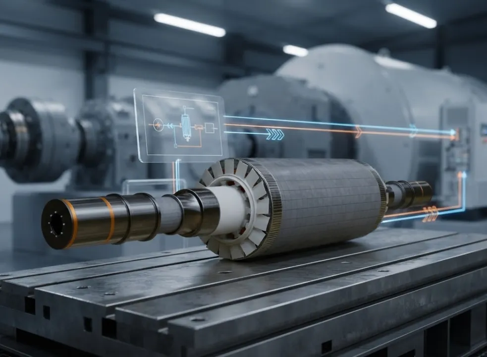
hardware-in-the-loop. The complete controller, including its firmware and its interfaces, is connected to a real-time simulation of the motor, inverter, and load. The controller believes it is driving a real machine: it issues PWM, reads back simulated current and position, and responds to simulated faults. This catches integration defects, interface errors, fault-handling behaviour, and control performance across the whole envelope, with no hardware at risk.

Power hardware-in-the-loop and motor emulator. The controller now drives real power through a real power stage, but the load on the other side is an emulated motor rather than a physical one. This validates the actual switching hardware, thermal behaviour, current sensing, and protection response under real electrical stress, while still allowing arbitrary load profiles and fault injection.

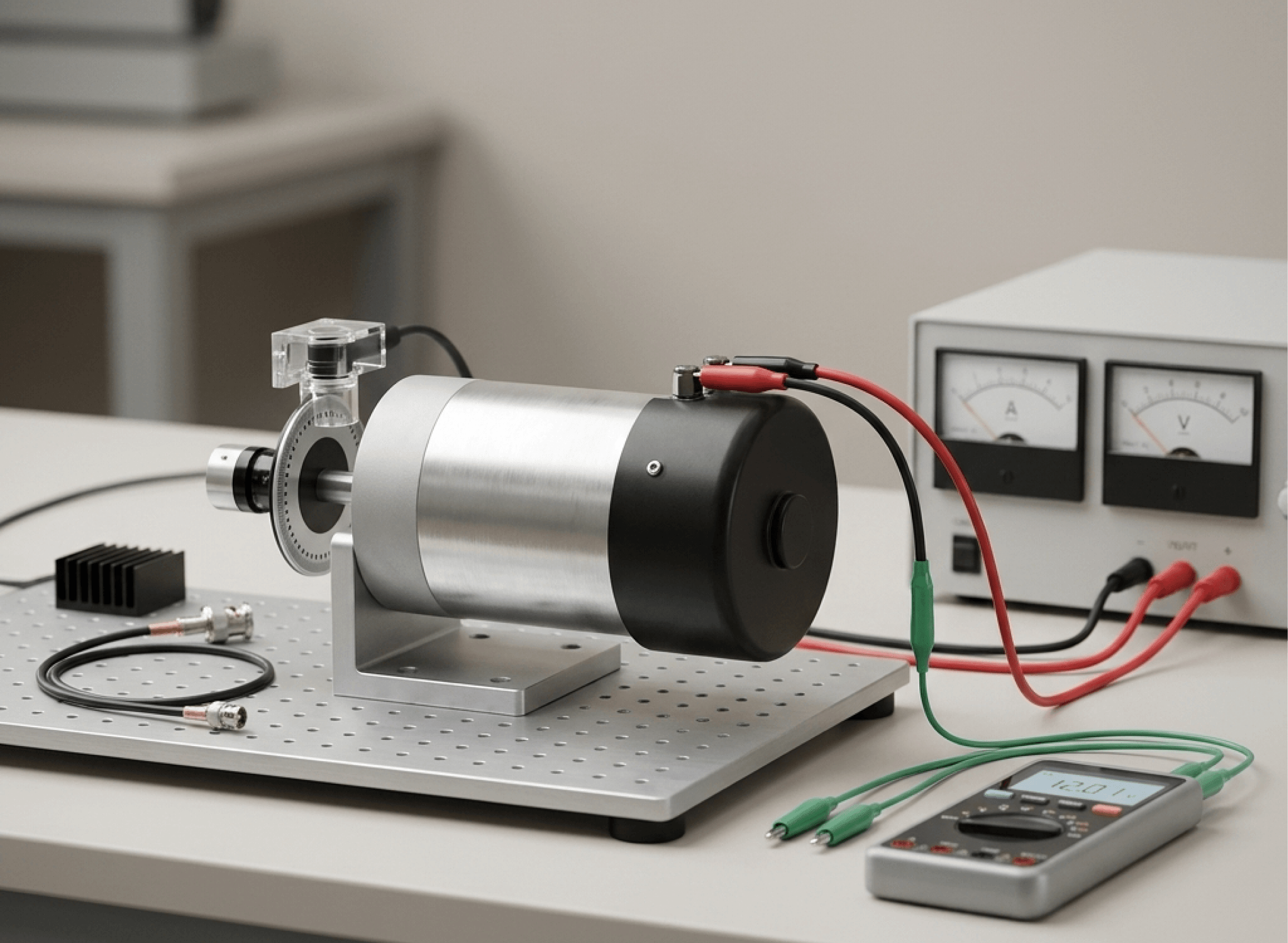
Dynamometer testing. The controller drives a real motor against a real mechanical load. This confirms end-to-end behaviour and captures effects no model reproduces perfectly. It is also slow, expensive, and unsuitable for exploring destructive corners.

Field validation. Final confirmation under real duty cycles and real environments, catching integration and environmental issues no laboratory reproduces.

The critical insight is that each stage is cheap to fix at and expensive to skip. A defect found in model-in-the-loop costs an afternoon. The same defect found on a dynamometer costs a motor, a controller, and a schedule slip. Found in the field, it costs a recall.

HIL and Power HIL for DC Motor Controllers

The two hardware-in-the-loop stages deserve closer attention, because they are where the validation gap actually closes.

Switching-edge resolution is the whole game. A DC motor controller switching at high frequency produces gate edges separated by fractions of a microsecond. A real-time simulator that samples those edges too coarsely will quantise them, and the resulting current waveform will not match what the real inverter produces. Duty cycle errors appear as current ripple that does not exist, or fails to appear when it should. FPGA-based simulation exists precisely to solve this: by running the power-stage model on reconfigurable hardware at nanosecond-scale time steps, the simulated inverter responds to gate edges with the fidelity the controller expects.

Motor and load emulation. The simulated machine can be any motor the programme needs, changed in software rather than by physically swapping hardware. The load can be constant torque, fan-law, inertial, or a recorded field duty cycle. Testing a controller against ten motor variants becomes a configuration change rather than ten procurement cycles.

Fault injection. This is the capability with no physical equivalent. Open phase, phase-to-phase short, phase-to-ground fault, DC-link collapse, DC-link overvoltage, encoder loss, encoder noise, Hall sensor failure, gate-driver failure, and thermal runaway can all be injected on command, at any point in the operating cycle, repeatedly, without destroying anything. Fault-handling firmware can finally be tested as thoroughly as normal operation.

Regenerative and four-quadrant testing without a dynamometer. Because the emulated load can absorb and return energy under model control, the controller can be exercised through every quadrant, including the hard regenerative transitions that cause DC-link overvoltage trips in service.

Automated regression across the full envelope. Once the test set is scripted, it can run unattended overnight against every firmware build. Coverage that was impractical with physical hardware becomes routine, and regressions surface in hours rather than after deployment.

How Impedyme Supports DC Motor Controller Development and Testing

Impedyme builds FPGA-based real-time simulation and testing platforms specifically for teams developing power electronics and motor control systems.

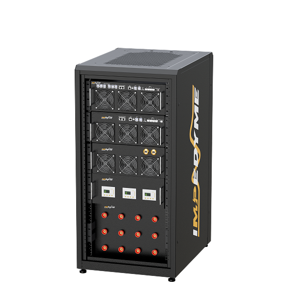
The CHP Series is the hardware platform underneath the workflow, providing the FPGA-based real-time computation and the high-bandwidth interfaces a motor controller needs to believe it is connected to a real machine.

MotorSim Studio provides the machine and drivetrain models: brushed DC, brushless DC, PMSM, induction, and switched reluctance machines, with configurable load profiles and mechanical dynamics, so a controller can be validated against the full range of motors it may drive.

PowerHIL Studio extends the same environment into Power HIL, where real power flows through the controller under test while the load remains emulated, enabling realistic electrical stress testing with full fault-injection control.

HIL/RCP-Box supports rapid control prototyping, letting teams run new control algorithms on real-time hardware against emulated plant before committing anything to a target processor.

Impedyme-RT provides the real-time execution environment tying models, I/O, and test automation together, including scripted regression across the operating envelope.

FPGA Scope gives visibility into signals inside the simulation at the resolution the switching behaviour demands, so that anomalies can be diagnosed rather than merely observed.

The Impedyme Simulink Blockset connects existing model-based design work directly into the real-time environment, so models developed during algorithm design carry through to hardware validation without being rewritten.

Together these shorten the path from control concept to validated hardware, and they move the discovery of faults from the field back into the laboratory, where fixing them is affordable.

Conclusion

A DC motor controller looks straightforward from the outside: apply a voltage, get a speed. The reality is a layered system in which a control core, a modulator, gate drivers, power switches, sensing, and protection all have to cooperate correctly across every operating point the machine will encounter. Choosing between DC motor controllers means matching peak as well as continuous ratings, understanding whether the load regenerates, and knowing where the control loop actually closes. Designing a DC motor controller circuit means confronting dead time, switching frequency, interference, thermal derating, and fault-response latency, whether the implementation is built around a compact DC motor controller IC or a fully discrete power stage.

What separates a controller that works from one that works reliably is not the sophistication of its DC motor control algorithm. It is how thoroughly that algorithm and its hardware have been exercised against real loads, real faults, and real regenerative events before anything reaches a customer. Whether the target is a small brushed axis or a high-power brushless DC motor controller, the operating envelope is far larger than any bench test practically covers. Real-time simulation, controller HIL, and Power HIL close that gap by making the difficult cases repeatable, safe, and automatable, and that is what turns a working DC motor controller into a dependable one.

Frequently Asked Questions 

Do all DC motors need a controller?

No. A DC motor can run connected directly to a supply, but it will run at whatever speed the load and supply voltage dictate, with no speed regulation, no reversing, no controlled stopping, and no protection against overcurrent or stall. Any application requiring regulated speed, controlled torque, reversing, or protection needs a DC motor controller.

What are the main types of DC motor controllers?

DC motor controllers are classified by the motor they drive (brushed, brushless, PMSM, induction, stepper, servo), by topology (H-bridge, three-phase inverter), by control method (on/off, voltage, PWM, PI/PID, six-step, field-oriented, direct torque), by loop type (open-loop, closed-loop, sensored, sensorless), and by operating quadrants (single-quadrant, two-quadrant, four-quadrant regenerative).

What is a brushless DC motor controller?

A brushless DC motor controller performs commutation electronically instead of mechanically. Because a brushless motor has no brushes or commutator, the controller must determine rotor position, either from Hall sensors, an encoder, or a sensorless estimation algorithm, and switch current between the windings accordingly. This adds control complexity but removes the wearing parts, reduces electrical noise, and extends motor life.

Can a DC motor controller recover energy during braking?

A four-quadrant regenerative controller can. When the load drives the motor rather than the other way around, the machine acts as a generator and energy flows back into the DC-link. A regenerative drive returns that energy to the supply or a battery. Where the supply cannot absorb it, a braking resistor dissipates it as heat instead. Handling this correctly is essential in lifts, hoists, traction systems, and high-inertia loads.

How is a DC motor controller tested before it drives a real motor?

Through a staged workflow: model-in-the-loop for the algorithm, software-in-the-loop for the code, processor-in-the-loop for target timing, then controller hardware-in-the-loop, where the real controller drives a real-time simulated motor and inverter. Power HIL follows, with real power flowing into an emulated motor. This allows fault injection, regenerative testing, and full-envelope regression without risking hardware, before any physical motor or dynamometer is involved.