Black start is the procedure for restarting a power grid after a total blackout, without drawing any electricity from outside. Most large plants need power to make power, so a black start system relies on a few self-starting sources: a black start generator, a hydro black start power plant, or a grid-forming black start battery running on stored black start energy. This guide explains what black start is, how a power grid black start up works step by step, and how engineers prove black start capability before the grid ever goes dark.
Black start is the process of restoring an electric power system, or part of one, from a total or partial shutdown without drawing energy from the external transmission network. A self-starting resource starts on stored energy alone. It energizes a pre-defined path of lines and transformers and uses that path to supply other plants and loads, until the system can be stabilized and reconnected.
The scope varies. A black start can restart an entire interconnection, a region separated from its neighbors, a single generating station, an industrial plant with its own generation, or a microgrid. A total shutdown means every generator and network element in the area is de-energized. A partial shutdown leaves some of the system alive, so restoration can usually lean on the live parts.
Three terms are often confused:
“Black start up”, “black start system” and “power grid black start” all describe the same concept. What matters most is that black start is the last-resort restoration plan, and it is a planned, drilled procedure, not an improvisation.
At bulk-system level, a power grid black start is run from the control room of the transmission system operator or ISO, in coordination with generator operators and distribution utilities. Every control area keeps a pre-approved restoration plan. The plan names the designated black start resources, the cranking paths to the next-start units, those next-start units themselves, and the substations where islands will be synchronized. In North America, NERC EOP-005-3 requires the transmission operator to verify its restoration plan by analysis or test at least once every five years and to give field and control-room personnel recurring restoration training. Generator operators with a power grid Blackstart Resource must give their operating personnel at least two hours of training every two calendar years. Drills and simulator sessions are how operators build the muscle memory for an event most of them will never see live.
Operators face three problems at once:
There is also a dependency chain outside the power sector. Gas pipeline compressors, water pumping, telecom sites and SCADA links all need electricity, and their backup supplies run out. The EU network code on electricity emergency and restoration requires critical tools and facilities used in the restoration plan to stay available for at least 24 hours after loss of primary power supply. Restored load is therefore prioritized: hospitals, water and wastewater treatment, fuel terminals, and data and telecom nodes come before general demand.
Every large plant consumes part of its own output. A thermal plant’s auxiliary or station-service load includes boiler feedwater and condensate pumps, circulating-water pumps, forced- and induced-draft fans, coal mills, lube-oil and seal-oil systems, fuel-gas compressors, control and protection systems, and excitation. A peer-reviewed study of Indian coal-fired stations (Bhatt and Mandi, 1999, “Performance enhancement in coal-fired thermal power plants. Part III: auxiliary power”) reports that auxiliary power accounts for 7% of gross generated power for 500 MW units and 12% for 30 MW units at full plant load. Combined-cycle plants are generally lower, and hydro plants need only a small fleet of auxiliaries, mainly oil pumps, cooling and controls.
The hard part is not the megawatts. It is motor starting on a weak, dead bus. A large induction motor started direct-on-line draws a starting current several times its rated current at poor power factor. On a bus fed by one small generator, that reactive surge pulls the voltage down deeply, which can stall other motors or trip undervoltage protection.
For the same reason, large coal, combined-cycle steam and nuclear units are next-start units, not black start units. Their thermal start times are long, their auxiliary demand is large, and nuclear units in particular operate under strict safety constraints on off-site power. They are the destinations of cranking paths, not the origins.
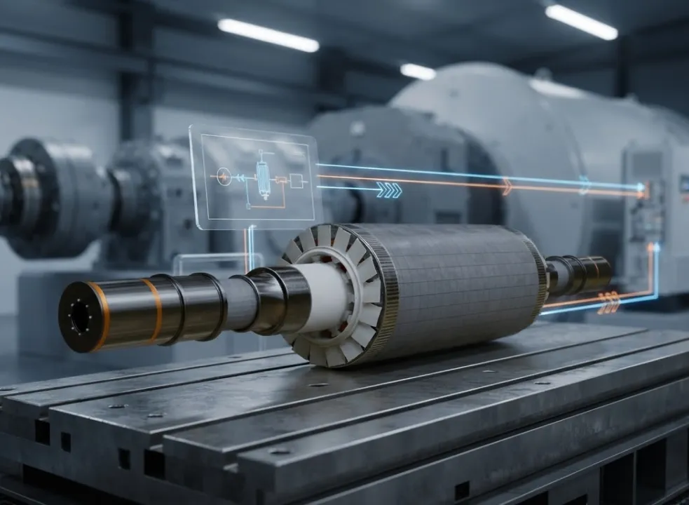
A synchronousreluctance motor generator has a rotor carrying a DC-excited field winding. As the rotor turns, its magnetic field sweeps the three-phase stator windings and induces a voltage. The induced voltage rises in proportion to both rotor speed and field flux, so at fixed speed the field current sets the terminal voltage.
That field current comes from an exciter. A static exciter rectifies power taken from the generator terminals or the station bus. On a dead machine there is no terminal voltage to rectify, so it needs an external or stored source to begin. Field flashing solves this: the station battery briefly drives DC into the field until terminal voltage builds enough for the exciter to sustain itself. A brushless exciter, especially one with a permanent-magnet pilot exciter, carries its own magnetic source on the shaft and can build voltage without external power. Some small machines rely on residual magnetism in the rotor iron alone.
During restoration, the AVR runs in voltage-control mode to hold the island bus voltage. The under-excitation limiter must stay active, because a generator energizing lightly loaded lines will be pushed to absorb reactive power. A well-designed black start system must coordinate excitation, voltage regulation, protection, switching and load pickup to prevent the recovering system from collapsing again.
Black start becomes necessary when an area loses all supply and cannot be re-energized from a neighbor. Typical triggers include:
Most outages, even large ones, are restored by back-feeding from neighboring live areas. A true black start from on-site stored energy is rare. The available black start energy source depends on the facility and its design. A black start battery may provide control power, protection power, field flashing or selected starting loads, while other systems use diesel generators, small hydro units or other independent sources. Battery capacity and duration must match the actual starting requirements.
Three wide-area events show the range:
The terms are worth keeping apart: a blackout is the loss of supply, and black start is the restart procedure.
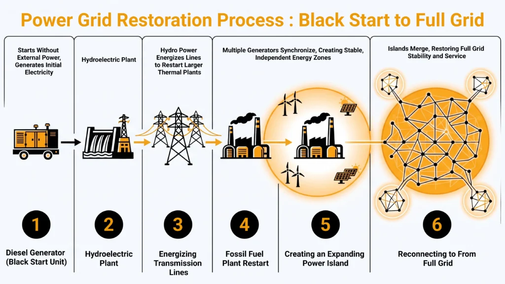
Every black start follows four stages: start the self-starting unit, energize the cranking path, pick up load, and build and synchronize islands. Each stage is pre-planned, with breaker positions, voltage targets and frequency targets defined before the event. Operators execute the plan; they do not design it under pressure. The table below summarizes the stages.
| Stage and objective | Key risks | Typical mitigations |
|---|---|---|
| 1. Start the black start unit: bring a self-starting source to rated speed, voltage and frequency on stored energy | DC battery or UPS depletion, failed field flash, fuel or water unavailability, control-mode errors | Tested DC systems, redundant start sources, isochronous governor and voltage-control AVR presets, restoration protection groups |
| 2. Energize the cranking path: build a dead-bus path to the next-start plant without picking up stray load | Line-charging overvoltage, Ferranti rise, under-excitation or self-excitation, transformer and sympathetic inrush, resonance overvoltage | Staged energization, shunt reactors, point-on-wave closing, voltage ramping (soft energization), pre-opened intermediate breakers |
| 3. Pick up load: add load in blocks while keeping frequency and voltage in bounds | Frequency nadir below protection thresholds, motor-start voltage dips, cold load pickup | Small feeder blocks, staged reconnection, tap-changer and protection coordination, temporarily disabled auto-reclose and selected UFLS stages |
| 4. Build and synchronize islands: merge live islands into one stable system | Out-of-sync closing, large standing phase angle, shaft torque impact, unit trips | Synchro-check relays, automatic synchronizers, redispatch to reduce angle, alternative closing points, PMU monitoring |
The self-starting source draws on stored energy. A diesel engine cranks from batteries or compressed air. A gas turbine is started by a diesel, a battery system or a static starter fed from one. At a hydro unit, the wicket gates are opened with stored hydraulic pressure and DC control power, and the field is flashed from the station battery. An inverter-based resource starts by forming AC voltage from its DC bus.
Once running, the unit switches control modes. The governor moves from droop to isochronous mode so that it holds frequency on its own. The AVR runs in voltage-control mode. Overcurrent Protection settings switch to restoration groups suited to low fault levels. None of this works without healthy DC station batteries, UPS units and black start panels. A depleted battery bank or a failed control-power supply is among the most common ways a black start fails before the first breaker closes.
The cranking path is a pre-defined, isolated route from the black start unit to the next-start plant. Intermediate breakers are opened beforehand so that no load is picked up unintentionally. Energizing it raises five physical problems:
Illustrative worked example (assumptions stated, not design data). Take a 400 kV, 50 Hz overhead line, 100 km long, with an assumed positive-sequence capacitance of about 12 nanofarads per kilometre. Its charging reactive power works out to roughly 60 MVAr. Now suppose the black start unit is a 100 MVA hydro generator that can absorb, say, about one-third of its rating in under-excited operation, roughly 33 MVAr (an assumed figure; the real limit comes from the machine’s capability curve). That machine cannot hold the line open-ended on its own. The plan would need a shunt reactor switched in first, a second unit in parallel, or a shorter first section.
Mitigations include staged energization (one section at a time), shunt reactors connected before or with the line, controlled or point-on-wave closing to limit transformer inrush, and voltage ramping, where the source energizes line and transformer together from low voltage so that charging and inrush build gradually.
Load is restored in blocks. Each block opens a gap between electrical demand and mechanical power, and frequency starts to fall. The initial rate of fall is proportional to the size of the load step and to nominal frequency, and inversely proportional to the inertia constant and the MVA rating of the machines online. The lowest point frequency reaches is the nadir. It depends on how fast the governor and prime mover respond, after which frequency recovers to a settling frequency (or back to nominal under isochronous control). Motor loads add a voltage dip from their starting current.
Illustrative worked example (assumptions stated). Consider a 100 MVA unit with an inertia constant of 4 seconds, running at 50.0 Hz, and an assumed under-frequency protection threshold of 49.0 Hz. As a deliberately conservative bound, assume the governor adds nothing useful during the first two seconds, when the nadir would otherwise form. The 1 Hz margin then allows an initial rate of fall of about 0.5 Hz per second. With this inertia and rating, that corresponds to a load block of roughly 8 MW, or 8% of unit rating. Real governor response allows more; motor starting and protection margins allow less. Plans typically confirm block sizes by dynamic simulation.
Cold load pickup compounds the problem. After a long outage, thermostatically controlled loads (heating, air conditioning, refrigeration) and motor loads lose their normal diversity, so when a feeder is re-energized they all draw power at once. An IEEE Power System Relaying Committee report documents a cold-load event in which restored current reached 6.7 times the pre-outage current. Peer-reviewed studies describe elevated demand persisting for minutes to tens of minutes until diversity returns.Mitigations include small feeder blocks, staged reconnection, coordination of load-tap-changers and protection, and temporarily disabling auto-reclose and selected under-frequency load-shedding (UFLS) stages so they do not drop the loads just restored.
Each black start unit grows an island around itself. To merge two live islands, operators close a substation breaker through a synchro-check relay or automatic synchronizer, which permits closing only when voltage magnitude, frequency (slip) and phase angle are matched within set limits.For synchronizing generators, IEEE C50.12 and C50.13 give the machine design limits as a phase angle within ±10 degrees, voltage within 0 to +5 percent, and slip within ±0.067 Hz. Synchro-check settings for line closures between islands are set by the operator from studies.
Closing out of synchronism produces a torque impact on nearby generator shafts, adds to shaft fatigue, causes high transient currents, and can trip units, collapsing one or both islands. In hardware tests on a microgrid testbed, two grid-forming batteries were deliberately closed together at a 15-degree angle difference. They rode through, but with about twice the peak current of a synchronized close.
A further issue is the standing phase angle across a line that closes a loop between islands, caused by power flowing on other paths. Operators reduce it by redispatching generation, shifting load between islands, or choosing a different closing point. Time-synchronized phasor measurement units (PMUs) give both sides of the breaker a common time reference, so angle and slip can be seen accurately before closing.
Top-down (backbone-first) restoration energizes the high-voltage backbone from a large source, often a neighboring system or a major hydro station, and then feeds plant auxiliaries and load downward. It needs few synchronizing events but depends on the backbone source being available.
Bottom-up restoration builds several islands in parallel around distributed black start units and merges them. It is faster because islands grow at the same time, but coordination is more complex: more synchronizing events, more protection changes, more communications. Microgrids and distributed energy resources (DER) fit naturally into bottom-up schemes as island seeds and load supports.In top-down schemes they can provide local support once the backbone voltage arrives. Great Britain’s Distributed ReStart innovation project (final findings, October 2023) trialled bottom-up restoration from distributed resources on live networks; as summarized in an Idaho National Laboratory paper, a “wind farm successfully energized 132kV and 275kV transmission system assets with grid-forming inverters,” using a 69 MW Scottish wind farm running virtual synchronous machine control.
Realistic black start power plant options include:
Gas plants carry a fuel interdependency. Pipeline compressors and on-site fuel-gas boosters need electricity, so a blacked-out region can starve its own gas units. During the February 2021 cold-weather event in Texas and the south-central U.S., the joint FERC–NERC inquiry found that 1,045 generating units experienced 4,124 outages, derates or failures to start. It also found that 87% of fuel-related outages and derates were due to natural gas supply, partly because power was lost at gas production facilities. Black start plans therefore specify on-site fuel inventory or dual-fuel capability.
Combined-cycle steam sections, large coal units and nuclear plants remain next-start units for the reasons covered above. The direction of travel is toward technology-neutral qualification: defining black start by required performance rather than by plant type.
A black start generator is a generating set that can start and reach stable voltage and frequency with no external electricity supply, meeting its own starting needs from stored energy: a battery, compressed air, a hydraulic accumulator or hydro head. The term covers three scales:
Selection criteria are start time, load acceptance per step, reactive range (especially absorbing capability), fuel autonomy, reliability, and the periodic test record.
A qualified black start resource must be able to:
The main standards documents:
Some jurisdictions now also set restoration-time targets. Under Great Britain’s Electricity System Restoration Standard, as set out in Ofgem’s code-modification decision, the system operator “must be capable of restoring 60% of Demand on the Transmission System in all regions within 24 hours, and of restoring 100% of Demand nationally within 5 days,” with the requirements to be met by 31 December 2026.
Procurement follows three broad models: cost-of-service recovery in regulated tariffs, flat-rate compensation for designated units, and competitive tenders that increasingly accept non-traditional and distributed resources.
A black start battery suits restoration well. It starts almost instantly, needs no fuel, has no large auxiliary motors, offers full four-quadrant reactive capability, and can ramp voltage smoothly from zero. The essential condition is that only grid-forming control can energize a dead bus. A grid-following inverter cannot.
Energy sizing logic. A black start battery must supply the power and energy to (a) crank a gas turbine’s auxiliaries and starting package through to synchronization, (b) hold a charged line or cable within its reactive limits, and (c) ride through load blocks until the turbine takes over. On top of that, the operator reserves a state-of-charge band that normal market operation may not use.
Illustrative sizing example (all assumptions stated, not design data). Assume a gas turbine whose starting package and essential auxiliaries draw a peak of 5 MW and an average of 3 MW over a 30-minute start-to-synchronization window. That is 1.5 MWh. Add one hour of island support at an average of 2 MW (2 MWh), for 3.5 MWh. Add a 25% margin for conversion losses, ageing and temperature, giving about 4.4 MWh. Reserving enough for a second start attempt pushes the reserved energy toward about 6 MWh. On the power side, the inverter must cover the 5 MW peak plus reactive demand and inrush headroom, so its MVA rating would sit well above 5 MW.
Documented demonstrations support this role. Imperial Irrigation District, a California utility, reported that on 10 May 2017 its 33 MW / 20 MWh battery supplied the power to start a 44 MW combined-cycle gas turbine at its El Centro Generating Station, then switched to absorbing the generator’s output while the plant stabilized.In February 2020 the turbine manufacturer announced the first battery-assisted black start of a 150 MW heavy-duty simple-cycle gas turbine at Entergy Louisiana’s Perryville Power Station, using a 7.4 MW battery system; the utility told POWER magazine that the test used the battery “to successfully start the 150-MW gas turbine two times on the same charge.”
A grid-following inverter behaves as a controlled current source. A phase-locked loop (PLL) tracks the existing grid voltage angle, and the inverter injects current synchronized to it. A grid-forming inverter behaves as a voltage source behind an impedance. It holds an internal voltage reference (magnitude and angle) and lets current follow the load. Common grid-forming methods include:
These behaviors are important when designing a black start system, where an inverter must establish and maintain a stable voltage reference without an energized grid.
A grid-following inverter cannot start on a dead bus for a concrete reason: its PLL has no voltage to lock to. Its anti-islanding protection is also designed to trip it, since IEEE 1547-2018 requires DER to detect an unintentional island, cease to energize and trip within 2 seconds. In weak grids with a low short-circuit ratio, grid-following controls can become unstable, while grid-forming controls help stabilize the voltage. Multiple grid-forming inverters in one island share load through their droop characteristics, with no fast communications needed. Reliable black start capability therefore depends on grid-forming control, adequate current headroom and coordinated protection.
Inverters are current-limited. Industry analysis presented in a NERC webinar puts the short-circuit current of inverter-based resources typically at 1.1 to 1.5 per unit of rated current. Synchronous machines, by contrast, deliver several times rated current for seconds; a peer-reviewed review cites five to ten times rated current for a period.
This has several consequences:
Hardware testing at U.S. national laboratories quantified this. Using soft start, a 110 kW / 140 kVA grid-forming battery black-started a microgrid whose transformer capacity exceeded its own rating by more than 3:1, with peak current under 70 A, compared with over 200 A for a diesel generator energizing the same system. When the battery instead closed onto the dead network almost instantly (“hard switch”), peak current rose to about 350 A. The battery could take load steps up to its rated power once the island was formed, but could black start only about one-third of its rated power at 0.8 power factor. A black start battery must therefore be evaluated for both energy requirements and the current limits imposed during network energization.
Mitigations follow from this: soft energization (ramping voltage from zero so transformers and lines are energized with negligible inrush), sequential energization, current-limit strategies that preserve voltage-source behavior (virtual impedance, for example), and restoration-specific protection based on voltage or direction rather than current magnitude. A power grid black start sequence should account for these factors to help maintain voltage stability and prevent inverter current limits from interrupting restoration.
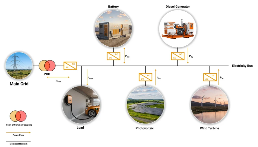
Conventional PV and wind plants cannot black start a grid. Their inverters are grid-following, their output depends on the weather, and their own auxiliaries (pitch systems, yaw drives, cooling, SCADA) need power. They can contribute in three ways: when paired with grid-forming storage, when wind converters are grid-forming and have an onboard auxiliary supply, or through an offshore VSC-HVDC link operating in grid-forming mode. In national-lab hardware tests, grid-following rooftop PV inverters joined a battery-formed island and supported restoration, but whether they rode through a large load step depended on their trip settings.
Homes are a separate case. A home solar inverter test battery with a transfer switch can island and restart the house’s own circuits. That is backup power, not a grid black start, and many residential systems still need a start signal or a minimum state of charge to re-form their microgrid after shutting down.
A microgrid black start follows a short, scripted sequence:
This pattern applies to island power systems and to critical facilities such as hospitals, water treatment plants, data centers and military bases. Several microgrids can also be coordinated to support bulk-system restoration, energizing feeders and substations from the bottom up. The main design choice is between master/slave control, where one grid-forming unit sets voltage and frequency and the others follow, and droop sharing, where several grid-forming units share load autonomously. Droop sharing is more resilient to losing a single unit; master/slave is simpler to tune.
Field black start tests are rare. They require de-energizing real assets, put equipment and customers at risk, and are scheduled infrequently: the minimum is once every three years under both NERC EOP-005-3 and the EU emergency and restoration code. Great Britain’s system operator states in its Electricity System Restoration Assurance Framework 2023/24 that “a Total System Shutdown event has never occurred in Great Britain; this makes it very difficult to test the performance of our restoration capability and arrangement in real time,” and its probabilistic modelling put the average time to restore 60% of national demand in 2023 at 32.1 hours. Capability is therefore proven in layers:
Sample black start test sequence for a grid-forming inverter (PHIL):
| Test step | Emulated condition | Quantities measured |
|---|---|---|
| Dead-bus start | Grid emulator presents a de-energized bus with transformer and line impedance | Voltage build-up time, voltage overshoot, waveform distortion |
| Transformer energization | Saturable transformer model, soft-ramp vs hard-close | Inrush peak, current-limit engagement, voltage sag depth |
| Line charging | Programmable capacitive line section | Reactive absorption, steady-state overvoltage, control stability |
| Load blocks | Stepped resistive, motor and constant-power loads | Frequency nadir and settling time per block, voltage dip, recovery |
| Current-limit stress | Motor start or fault beyond rating | Current-limit behavior, retained synchronism, recovery time |
| Cold load pickup | Load model with lost diversity | Sustained overload handling, SOC draw from battery emulator |
| Island resynchronization | Second source with controlled slip, voltage and angle offset | Synchronizing angle at closure, closing transient current and power swing |
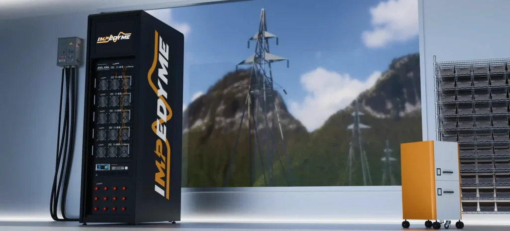
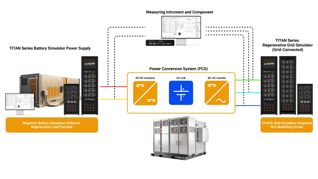
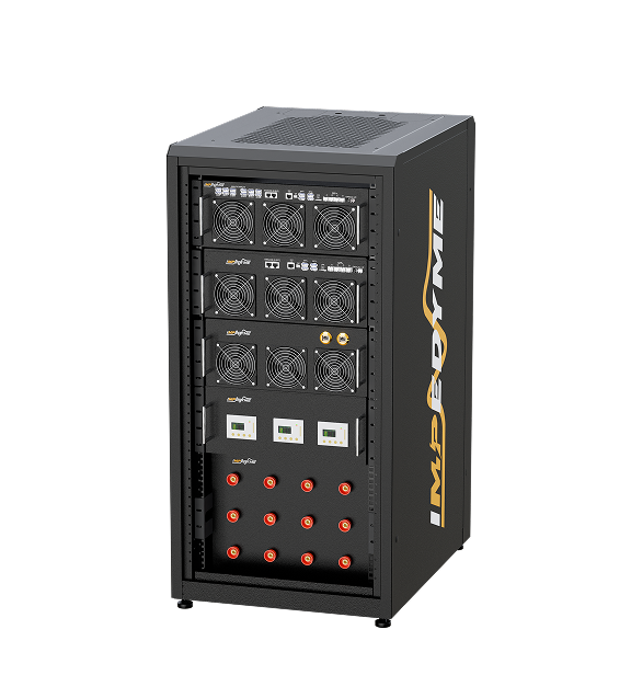
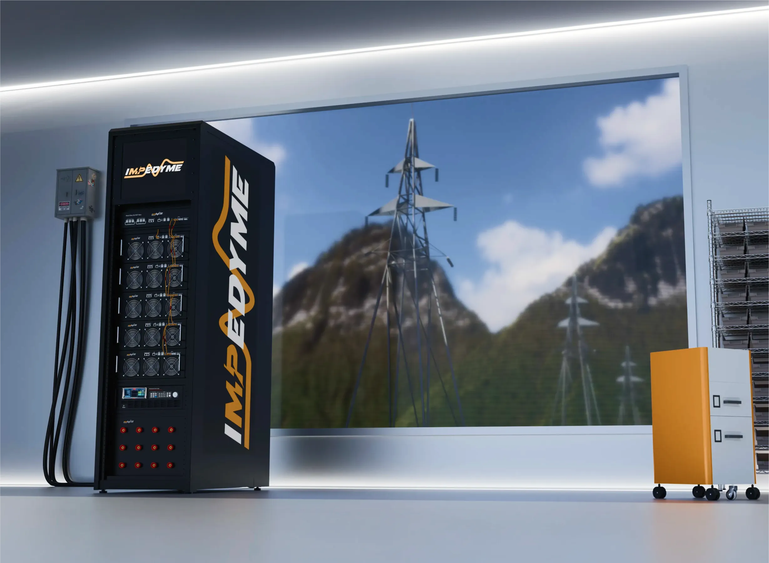
Impedyme’s role. Impedyme’s CHP Series Grid Emulator is a regenerative grid simulation platform built for HIL and PHIL. It sources and sinks up to 100% of rated power, delivers up to 110 kVA/kW per cabinet, parallels up to 550 kVA/kW, and is available in custom three-phase configurations of 1.3 MW and above on request. Through GridSim Studio it offers independent per-phase voltage and frequency control, phase-shift and harmonic injection, a real-time R, L, C, RL, RC or RLC grid-impedance model, configurable soft-start ramping, and automated IEEE 1547 ride-through sequences. On the DC side, BatterySim Studio and the Real-Time Battery Emulator run battery models on the FPGA-based CHP platform with model steps as low as 90 ns. Together with Impedyme-RT, PowerHIL Studio, FPGA Scope, the HIL/RCP-Box and the Impedyme Simulink Blockset, this lets one bench move a grid-forming controller from Simulink model to CHIL to full-power PHIL black start testing.
PHIL stability depends on the interface algorithm (ideal transformer method, damping impedance and similar) and on total loop latency. Both must be selected and verified for the impedance range under test, or the test rig rather than the device will set the result.
A black start begins with a simple paradox: power plants need power to make power, so every power grid black start depends on a few self-starting sources, such as a hydro black start power plant, a battery-started black start generator, or a grid-forming black start battery running on stored black start energy. Restoration is never improvised. A black start system follows a pre-planned, four-stage sequence: start the unit, energize the cranking path, pick up load, and synchronize islands. At each stage the main dangers are electromagnetic and dynamic: line-charging overvoltage, transformer inrush, frequency nadir and out-of-sync closing. As synchronous plants retire, black start capability is moving to inverter-based resources, which behave very differently under fault and inrush conditions. A real black start up cannot be rehearsed at will on a live network, so simulation, CHIL and PHIL testing with platforms such as Impedyme’s grid and battery emulators have become part of how a resource qualifies. The answer to “what is black start?” is shifting from a list of approved plant types to a set of performance requirements, and any technology that can prove that performance before the grid goes dark can meet them.
How long does a black start take?
It depends on system size and strategy. After the 28 April 2025 Iberian blackout, transmission restoration took about 12 hours in Portugal and 16 hours in Spain. After the 2003 North American blackout, some U.S. areas waited four days. Great Britain’s restoration standard targets 60% of demand in every region within 24 hours and 100% within five days.
Can batteries provide black start?
Yes, if they use grid-forming inverters. Imperial Irrigation District reported in 2017 that its 33 MW / 20 MWh battery started a 44 MW combined-cycle gas turbine.National-lab hardware tests showed a grid-forming battery energizing transformers rated more than three times its own capacity by soft start.
Why can’t solar black start the grid?
Most solar inverters are grid-following. They need an existing voltage to lock onto, and IEEE 1547-2018 requires them to trip within 2 seconds of an unintentional island Solar output also depends on weather. PV can support restoration once a grid-forming source has re-established voltage.
How is black start capability tested?
Through simulation, controller and power hardware-in-the-loop testing, and periodic field tests. NERC EOP-005-3 and the EU emergency and restoration code both require black start resources to be tested at least once every three years.PHIL testing with a grid emulator lets engineers rehearse dead-bus starts, inrush, load blocks and resynchronization at full power without de-energizing a real network.
Why is hydropower the most common black start resource?
Hydro plants have minimal auxiliary load, start and ramp quickly, and can absorb the reactive power of long unloaded lines. Oak Ridge National Laboratory found that hydro supplies about 40% of U.S. black start resources despite being about 10% of capacity.
What is cold load pickup?
Cold load pickup is the surge in demand when a feeder is re-energized after a long outage, because heating, cooling and motor loads all restart together instead of cycling with their usual diversity. An IEEE relaying committee report documents restored current reaching 6.7 times pre-outage current in one event.