
Electric motor control has quietly become one of the most important disciplines in modern engineering. According to the IEA 4E Electric Motor Systems Platform (EMSA) Policy Brief, “In 2023, electric motor systems were responsible for 53% of global electricity consumption.” This guide explains how HIL testing for electric motor control lets engineers validate PMSM controllers safely, earlier, and faster using FPGA-based real-time simulation — and how Impedyme’s ecosystem of hardware and software brings the entire workflow into one platform.
Electric motors are the invisible workhorses of the modern world. They move vehicles, drive factory lines, circulate air in buildings, pump water on farms, and spin the compressors inside nearly every appliance. As electrification accelerates across transportation, industry, and energy, the software and power electronics that control these motors have become the decisive factor in efficiency, reliability, and safety.
Two forces are pushing motor control engineering harder than ever. The first is the relentless drive for energy-efficient power electronics. The IEA 4E EMSA Policy Brief breaks the picture down by sector: “Their share in electricity consumption varies widely across sectors: 72% in industry, 36% in buildings, 87% in agriculture and 86% in the transportation sector.” When motors dominate electricity use to that degree, even small gains in inverter and controller efficiency scale into enormous energy and emissions savings.
The second force is the rise of smart controller software. A modern permanent magnet synchronous motor (PMSM) drive runs sophisticated field-oriented control (FOC) algorithms, manages thermal limits, coordinates regenerative braking, and executes safety functions — all in real time, on an embedded controller, at switching frequencies that keep climbing as wide-bandgap semiconductors (SiC and GaN) become mainstream.
The problem is that testing this software the old way — on a physical motor, a dynamometer, or in the field — is slow, expensive, and often dangerous. That is where hardware-in-the-loop (HIL) testing for electric motor control transforms the development process.
Hardware-in-the-loop testing is a real-time simulation approach in which the actual controller hardware runs production or production-intent software while interacting with a simulated physical system. Instead of connecting your motor controller to a real motor and inverter, you connect it to a real-time target that mathematically emulates the motor, the inverter, and the sensors — reproducing the electrical and timing behavior the controller expects.
The controller under test — the device under test, or DUT — cannot tell the difference. It sends PWM switching commands to what it believes is a real inverter, and it receives back motor currents, DC-link voltage, and rotor position exactly as a physical machine would produce them. The result is a closed loop that behaves like a bench or field test but without exposing expensive equipment or people to harm.
For electric motor control specifically, there are two closely related techniques:
Impedyme builds its entire platform around this progression — from signal to power — using FPGA-based real-time targets that eliminate the latency bottlenecks of traditional processor-based systems.
The motivation for adopting HIL testing for electric motor control comes down to six concrete advantages.
Shorting an inverter leg, forcing an overcurrent, or spinning a motor past its rated speed on a real bench can destroy hardware and injure people. In simulation, these events are just numbers. A simulated short circuit repeats exactly, so you can verify trip handling and recovery logic as many times as you want with zero risk to physical motors, inverters, or batteries.
With HIL, you can begin validating control firmware and protection logic as soon as a controller exists — long before a full power prototype, a motor sample, or a dyno cell is available. This catches the cheapest-to-fix defects first, when they are inexpensive to correct.
Every physical test cycle — build, wire, instrument, run, tear down — costs days. HIL collapses those loops into minutes. Because the plant is software-defined, engineers change a motor parameter or a fault scenario with a mouse click rather than a rewiring job.
Motor drives must satisfy functional requirements, EMC limits, and functional-safety standards. HIL provides a repeatable, traceable environment where each requirement can be linked to a test case and verified automatically, generating the documentation that certification demands.
HIL reduces the test to just the controller and its software, simulating the complete environment around it. The test becomes a clean black-box test at the controller’s pins, so a failure points unambiguously at the controller rather than at a noisy, uncontrolled physical rig.
Because the plant is deterministic and the bench is safe, tests can run unsupervised, overnight, and around the clock. Engineers can sweep the entire torque-speed map and inject rare faults that would be impractical or dangerous to reproduce physically — dramatically expanding coverage.
Impedyme structures motor control validation as a continuous workflow with three stages. The power of the approach is that the same models and test assets carry forward at every stage, so engineers never have to rewrite their work when they move from simulation to hardware.
| Stage | What It Validates | Impedyme Platform |
|---|---|---|
| Desktop simulation | Control algorithm logic and model behavior — offline, no power, no physical motor | Model-based design tools + Impedyme Simulink Blockset |
| Controller HIL (signal-level) | Embedded controller firmware against a virtual PMSM and inverter — low-voltage signals only, no physical motor | CHP Series / RCP-Box + MotorSim Studio |
| Power HIL (PHIL) | Controller and power stage at full traction power via motor emulation — real power flows, but the motor is emulated | CHP Series motor emulator + PowerHIL Studio |
| Dynamometer / mechanical | Final system under real mechanical load — full power plus mechanical, physical motor required | Dynamometer testbench |
Engineers first build high-fidelity models of the controller and the plant — the PMSM and inverter — in a desktop simulation environment. Here the control algorithm is developed and refined virtually, before any hardware is involved. This is where a reference behavior is established that later HIL tests will be compared against.
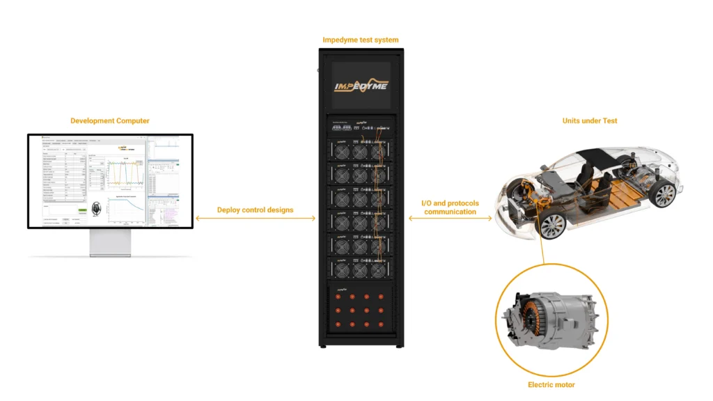
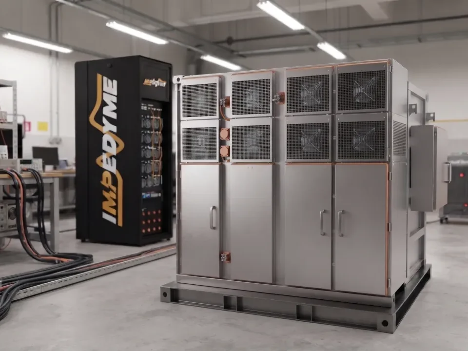
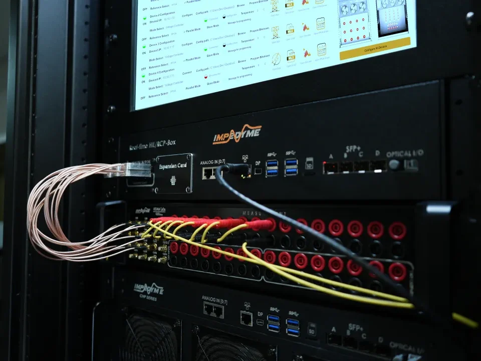
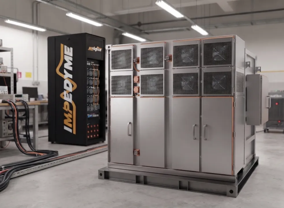
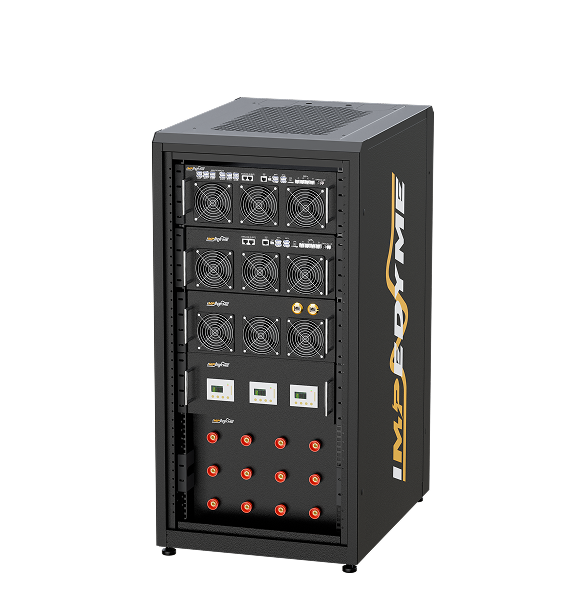
Next, the embedded controller becomes the device under test. The motor and inverter models are deployed to an FPGA-based real-time target — an Impedyme CHP Series system or HIL/RCP-Box — running MotorSim Studio. The controller runs its real firmware and interacts with the virtual motor in a closed loop at microsecond time steps.
Finally, testing moves into the power domain. Impedyme’s PHIL capability adds a regenerative power interface — a high-bandwidth power amplifier co-designed with the FPGA real-time core — that turns the simulated motor into real current and voltage. A physical inverter is now driven by an emulated motor that sources and sinks genuine power, with no physical machine or dynamometer required. This is where component stress, thermal behavior, and full-power protection are validated.
To make the concept concrete, consider a representative controller HIL test of a PMSM drive, genericized to the Impedyme ecosystem.
The device under test is an embedded motor controller running a field-oriented control algorithm. It is wired to an Impedyme CHP Series real-time target instead of a real motor and inverter. The closed loop works like this:
From the controller’s perspective, a real motor is spinning. Engineers watch it command a speed, see the virtual motor accelerate, and observe balanced three-phase currents develop — all on screen, with no rotating mass anywhere in the lab.
A disciplined HIL test starts from named requirements and ends with numeric checks. In this walkthrough, two example requirements illustrate the idea:
Each requirement maps to a test case with defined initial conditions, stimulus, and pass criteria. When the automated test runs, it verifies the requirement and records the result, creating the traceable evidence chain that validation and certification teams need.
One of the most important decisions in motor control HIL is how to model the inverter. There are two fundamentally different approaches, and choosing correctly determines whether your test reveals real behavior or hides it.
An averaged (ideal) inverter model represents the inverter using controlled voltage sources that reproduce the average behavior over a PWM period. It is computationally cheap and runs comfortably on a CPU at relatively coarse time steps. It is excellent for validating slow dynamics — speed loops, DC-bus energy balance, system-level coordination — where the fine detail of switching is irrelevant.
A switching-level inverter model represents each semiconductor switch explicitly. It reproduces the actual on/off transitions, and therefore the current ripple, torque ripple, dead-time distortion, and switching harmonics that a real inverter produces. This detail is essential when you are developing the control for the inverter itself, or when protection logic trips on instantaneous peak currents rather than filtered averages. The catch is that it demands a very small time step — which is exactly why an FPGA is required.
| Attribute | Averaged (Ideal) Inverter Model | FPGA Switching-Level Inverter Model |
|---|---|---|
| Switch representation | Controlled voltage sources (averaged) | Each semiconductor modeled explicitly |
| Typical execution | CPU, coarse time step | FPGA, sub-microsecond time step |
| Current ripple visible? | No — muted by averaging | Yes — reproduced faithfully |
| Torque ripple visible? | No | Yes |
| Switching harmonics / EMC insight | No | Yes |
| Instantaneous peak-current faults | Missed | Captured |
| Best for | Speed loops, system-level dynamics | Inverter control, protection, ripple, EMC |
| Computational cost | Low | High (requires FPGA parallelism) |
An averaged model on a CPU will slow down until ripple and peak currents are muted, and hardware protection that would trip on a real bench misses the same trigger in simulation — leaving teams tuning around a simulator artifact instead of a real control issue. The FPGA solves this because it co-locates computation and I/O on the same chip, eliminating bus-transfer latency.
In an Impedyme FPGA-based real-time target, PWM gate edges are captured at nanosecond-scale resolution — on the order of a few nanoseconds — while the motor and inverter model updates at approximately one microsecond, driven by an FPGA clock running at roughly 200 MHz. Impedyme’s CHP platform pushes model updates as fast as 90 nanoseconds, performing hundreds to over a thousand updates per electrical period. That temporal resolution is what allows the emulated motor to reproduce saturation, cross-coupling, torque ripple, and back-EMF harmonics faithfully.
The stakes are quantitative. Impedyme notes that a 25-microsecond simulation loop reproducing an 8 kHz PWM can introduce up to 20% error, while sub-microsecond time steps cut that error to under 1%. In motor control, that difference is the line between a test you can trust and one you cannot.
Once the switching-level model is running, engineers can use Impedyme FPGA Scope to observe the signals that matter. FPGA Scope is a built-in, high-speed visualization tool embedded directly in the real-time signal path, capable of monitoring up to 16 simultaneous channels — phase currents, dq-axis currents, phase voltages, PWM edges, and internal controller states — at sub-microsecond resolution, without any external oscilloscope or DAQ hardware.
With the switching model, current ripple appears as the small high-frequency oscillation superimposed on the fundamental current waveform. This ripple is a direct consequence of the PWM switching acting on the motor’s winding inductance. It drives torque ripple, which in turn causes noise, vibration, and additional losses.
Engineers can run harmonic analysis on the captured waveforms to quantify the distortion and understand its spectral content — critical for anticipating electromagnetic compatibility (EMC) problems before they show up in an EMC lab. The high-frequency content that a switching-level model reveals is precisely the content that averaged models delete by construction, and precisely the content that determines EMI behavior.
A classic mitigation is to raise the PWM switching frequency. Current ripple is inversely proportional to switching frequency: increasing the frequency shortens the interval over which current can drift between switching events, so the ripple shrinks. This inverse relationship is well established — as an illustrative example, a CERN technical report on high-precision power converters notes that raising switching frequency “from 5kHz that is currently used, up to 60kHz and beyond … gives an increase in accuracy by an order of magnitude or more.” Raising a drive’s PWM frequency to 20 kHz — above the audible range — reduces current ripple, smooths torque, lowers audible whine, and cuts harmonic content, at the cost of higher switching losses.
Because HIL makes this a software change rather than a hardware rebuild, engineers can sweep the PWM frequency, observe the improvement in ripple and harmonics in real time on FPGA Scope, and find the optimal trade-off between ripple, losses, and thermal stress — all in a single afternoon.
Some of the most valuable HIL tests are the ones you could never safely run on real hardware. Fault-injection HIL is built to answer one question: what does the controller do when conditions break normal limits?
For a PMSM drive, the critical fault scenarios include short circuits in the inverter legs, phase loss, DC-link collapse, overcurrent events, over-speed, and sensor failures. On a physical bench, forcing a short circuit through an inverter leg stresses devices, varies run to run, and risks catastrophic damage. In HIL, the same fault is a scripted, perfectly repeatable event.
| Fault Scenario | What It Tests | Why HIL Is Superior |
|---|---|---|
| Inverter leg short circuit | Overcurrent protection, shoot-through response | Destroys real hardware; safe and repeatable in HIL |
| Overcurrent event | Current-limit and trip thresholds | Precise, timed injection without device stress |
| Phase loss / open circuit | Fallback and ride-through logic | Hard to stage physically; trivial in simulation |
| DC-link voltage sag | Low-voltage restart and control margin | Dangerous at power; deterministic in HIL |
| Over-speed | Speed-limit enforcement | Risk of mechanical failure on real motor |
| Sensor / resolver fault | Fault detection and safe-state entry | Repeatable at exact timestamps |
A typical scripted scenario shows the power of the approach: the test runs normally, then at exactly 5 seconds a short-circuit fault is injected. The controller’s protection logic should detect the overcurrent and shut off the PWM within its specified response time. Because the fault triggers on a timestamp and the plant is deterministic, the test verifies not only that protection fires, but that it fires fast enough and recovers cleanly — every single run.
This is impossible or prohibitively dangerous with real hardware, but straightforward and safe with HIL. It is one of the strongest arguments for adopting HIL testing for electric motor control.
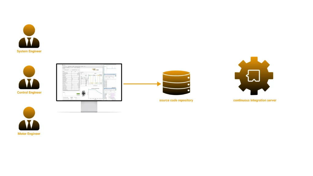
The final piece of the workflow is automation. Once a HIL bench is safe and deterministic, motor control testing can join the same continuous-integration (CI) practices that software teams have used for decades — something that was traditionally impossible for power electronics because lab testing was too slow and expensive to run on every code commit.
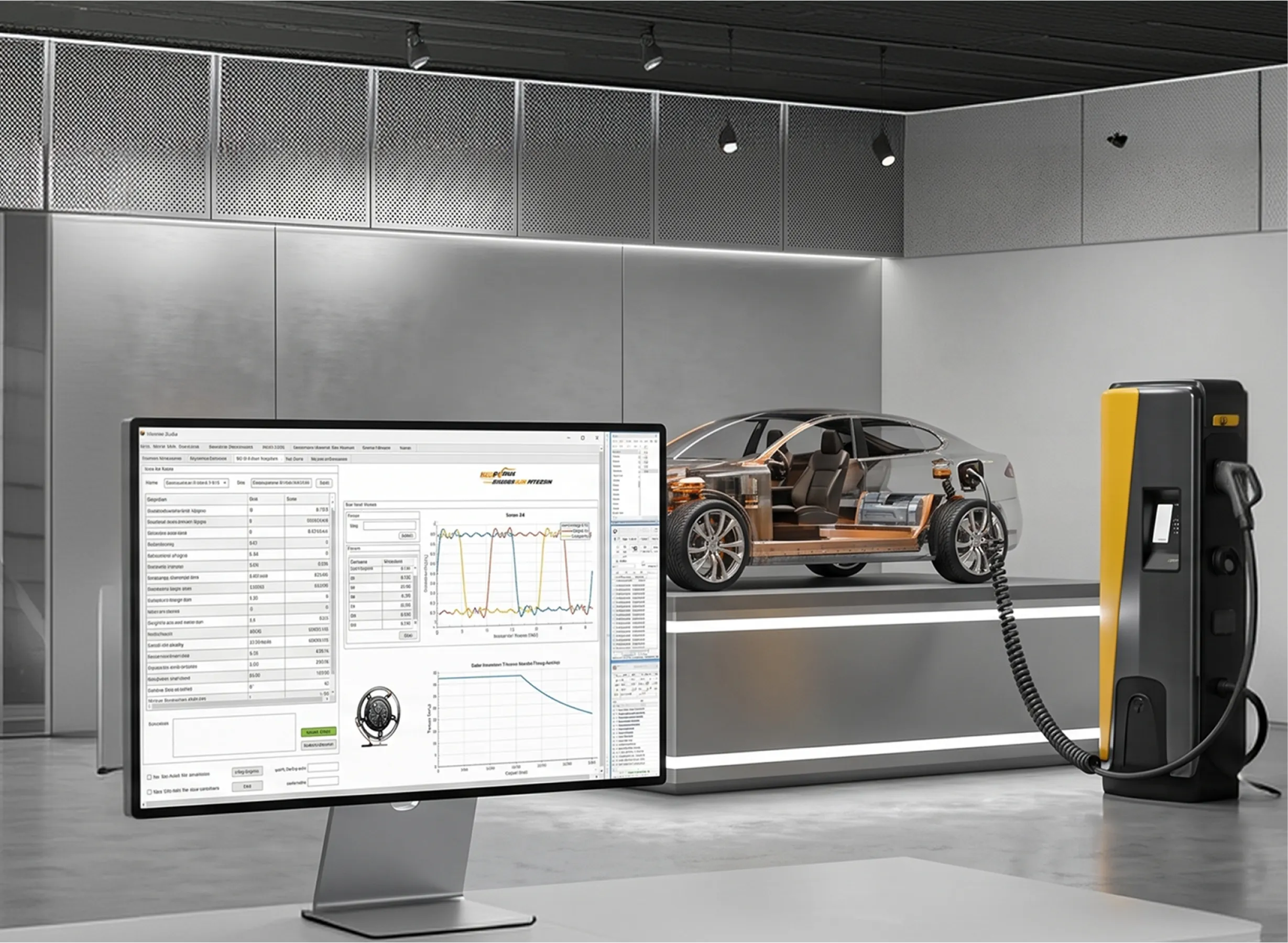
With Impedyme PowerHIL Studio orchestrating the bench, engineers can build automated test campaigns using a scenario and sequence editor: drive cycles, ramps, step changes, and fault scenarios, with automated pass/fail criteria and reporting of key metrics such as current ripple, torque ripple, efficiency, and protection response. PowerHIL Studio also enforces built-in safety and limit management with configurable current, voltage, and power limits and controlled shutdown.
A mature motor control CI workflow looks like this:
Because the tests are scripted and the bench is safe, the whole suite runs unsupervised. Test execution that once took weeks in a power lab can complete in under an hour, and the same test assets remain valid from the earliest signal-level testing through full-power PHIL validation.
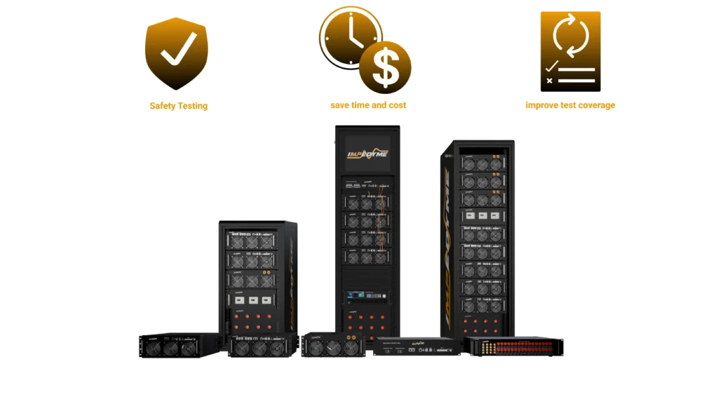
What makes this workflow seamless is that Impedyme delivers every piece as an integrated ecosystem, so models and test assets flow from desktop simulation to full power without being rewritten.
Together these components enable Combined Hardware-in-the-Loop and Power (CHP) testing, letting engineers validate control logic and power electronics simultaneously.
This same platform extends naturally to adjacent validation challenges. Teams working on motor control HIL often also need BMS HIL testing for battery management systems, full EV powertrain HIL for system-level validation, and inverter testing at full traction power — all of which run on the same CHP Series hardware and software ecosystem.
A common question is when to use each testing stage. The answer is that they are complementary, not competing, and the right program uses all of them in sequence.
| Method | Fidelity | Cost & Safety | Best Use |
|---|---|---|---|
| Desktop simulation | Model-level only | Lowest cost, no risk | Algorithm design, early logic checks |
| Controller HIL (signal) | High timing fidelity, no power | Low cost, very safe | Firmware, protection logic, fault injection |
| Power HIL (PHIL) | Full electrical fidelity at power | Moderate cost, safe (emulated) | Power-stage stress, thermal, full-power protection |
| Dynamometer | Full mechanical fidelity | High cost, real hazards | Final system validation, efficiency mapping |
The guiding principle is to start at the signal level early, move to PHIL for power-stage and envelope coverage once the power stage is available, and reserve the dynamometer for final mechanical validation. Making FPGA-based, microsecond-or-faster time-step fidelity a hard requirement ensures that coarse simulation never misrepresents switching behavior along the way.
Based on the workflow above, here is a staged, actionable path — and the benchmarks that should govern each decision.
HIL testing for electric motor control has evolved from a nice-to-have into the central gate for validating PMSM drives. It lets engineers test safely, test earlier, iterate faster, ensure compliance, isolate the controller, and automate coverage of edge cases that no physical bench could safely reproduce. The key enabler is FPGA-based real-time simulation, which alone can reproduce the switching-level ripple, torque ripple, and fault behavior that determine whether a drive is genuinely ready for production.
Impedyme brings the entire workflow — desktop simulation, controller HIL, and full-power PHIL — into one integrated ecosystem built around the CHP Series, MotorSim Studio, PowerHIL Studio, FPGA Scope, RCP-Box, and Impedyme-RT. The result is faster development, safer validation, and higher-fidelity results from the first line of control code to the final full-power test.
What is HIL testing for electric motor control?
HIL (hardware-in-the-loop) testing for electric motor control is a real-time simulation method in which an embedded motor controller runs its real software while interacting with a virtual PMSM and inverter running on a real-time target. The controller sends PWM commands and receives simulated currents and rotor position, forming a closed loop that behaves like a real motor drive without any physical motor.
What is the difference between an averaged and a switching-level inverter model?
An averaged inverter model represents the inverter with controlled voltage sources and captures only average behavior, making it cheap to run but blind to ripple and switching harmonics. A switching-level model represents each semiconductor switch explicitly, reproducing current ripple, torque ripple, and harmonics — essential for inverter control development, protection testing, and EMC analysis. Switching-level models require FPGA execution.
How does HIL testing handle inverter fault injection?
HIL lets engineers inject faults such as inverter-leg short circuits, phase loss, overcurrent, DC-link sag, and over-speed as scripted, perfectly repeatable events. For example, a short circuit can be triggered at exactly 5 seconds to verify that the controller’s overcurrent protection shuts off the PWM within its specified time. These tests are dangerous or impossible on real hardware but safe and repeatable in HIL.
Can motor control HIL testing be automated for continuous integration?
Yes. With PowerHIL Studio, test campaigns can be scripted with automated pass/fail criteria, compared against desktop simulation baselines within defined tolerances (such as 10%), and triggered automatically when developers commit new firmware. This brings continuous integration and regression testing to power electronics, reducing test cycles from weeks to under an hour.
What is the difference between HIL and Power HIL (PHIL) for motor drives?
Controller HIL tests the embedded controller at the signal level against a virtual motor, with no real power flowing. Power HIL (PHIL) adds a regenerative power interface so real voltage and current flow between an emulated motor and a physical inverter, enabling full-power validation of the power stage without a physical motor or dynamometer.
Which Impedyme products are used for PMSM controller HIL testing?
PMSM controller HIL testing on the Impedyme platform uses the CHP Series or RCP-Box FPGA-based real-time targets, MotorSim Studio for high-fidelity motor emulation, PowerHIL Studio for test orchestration and automation, FPGA Scope for sub-microsecond signal monitoring, and Impedyme-RT to connect model-based design tools to the hardware.