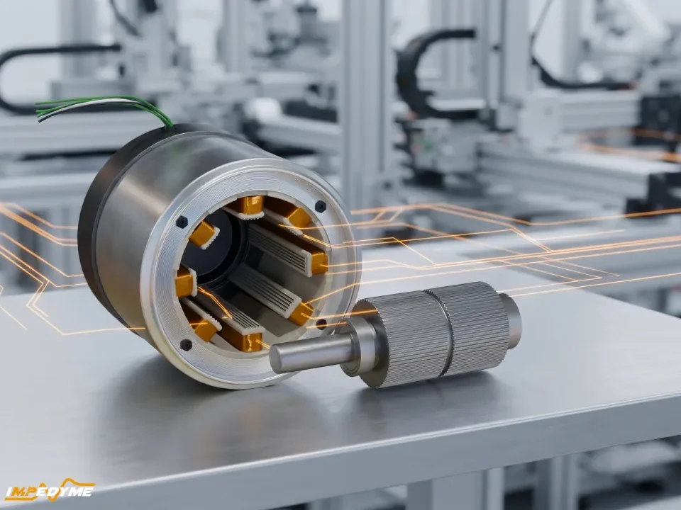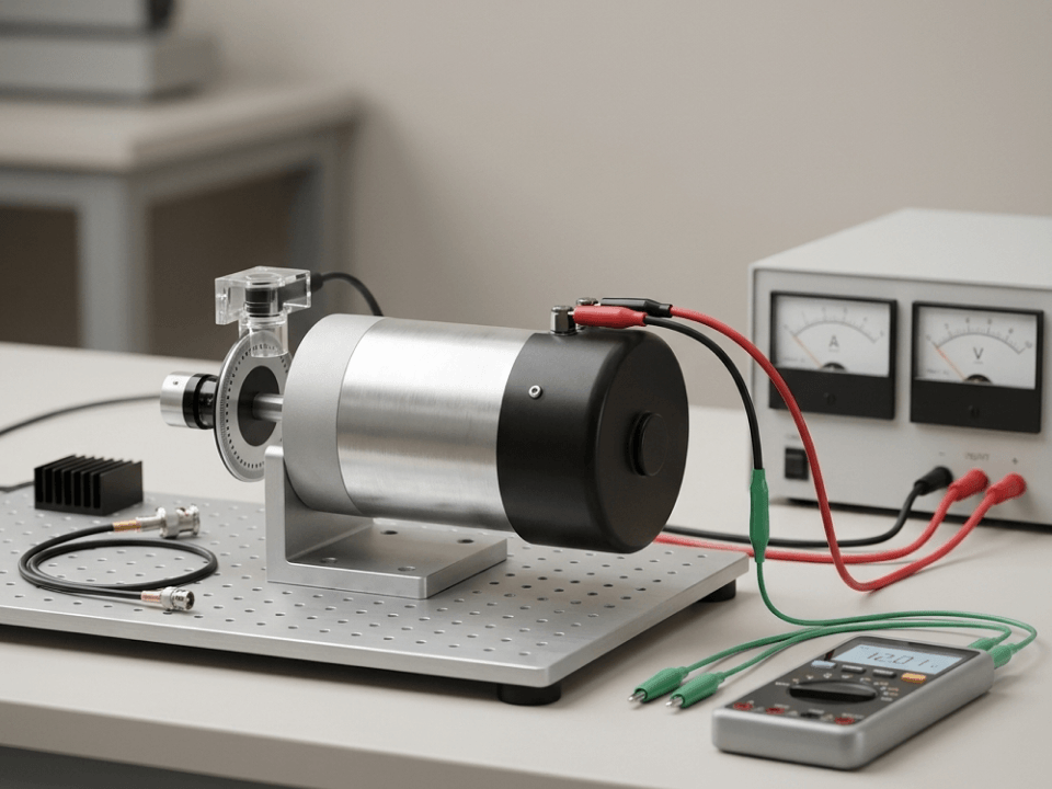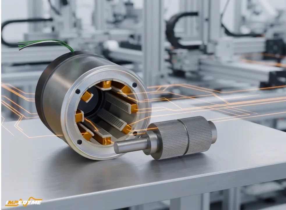
电机控制已悄然成为现代工程中最重要的学科之一。根据 IEA 4E 电机系统平台(EMSA)政策简报,“2023 年,电机系统占全球用电量的 53%。”本指南将阐述电机控制的 HIL 测试 如何让工程师借助基于 FPGA 的实时仿真,更安全、更早、更快地验证 PMSM 控制器,以及 Impedyme 的软硬件生态系统如何将整个工作流程整合到一个平台中。
电机是现代世界中无形的主力军。它们驱动车辆、带动工厂生产线、在建筑物内循环空气、在农场抽水,并驱动几乎每一种电器内部的压缩机。随着交通、工业和能源领域的电气化加速推进,控制这些电机的软件与电力电子设备已成为决定效率、可靠性和安全性的关键因素。
有两股力量正以前所未有的强度推动着电机控制工程的发展。第一股是对高能效电力电子设备的不懈追求。IEA 4E EMSA 政策简报按行业对这一情况进行了细分:“电机在各行业的用电占比差异很大:工业为 72%,建筑为 36%,农业为 87%,交通运输业为 86%。”当电机的用电占比达到如此程度时,逆变器和控制器效率即便是微小的提升,也能带来巨大的能源和减排效益。
第二股力量是智能控制器软件的兴起。现代 永磁同步电机(PMSM) 驱动器运行着复杂的 磁场定向控制(FOC) 算法,管理热限值,协调再生制动,并执行安全功能——所有这些都在嵌入式控制器上实时完成,而且随着宽禁带半导体(SiC 与 GaN)逐渐成为主流,开关频率还在不断攀升。
问题在于,用老办法测试这些软件——在实体电机、测功机上或现场进行——既缓慢、昂贵,往往还很危险。而这正是电机控制的硬件在环(HIL)测试彻底改变开发流程之处。
硬件在环测试是一种实时仿真方法,其中真实的控制器硬件运行量产或量产级软件,同时与被仿真的物理系统交互。你不是把电机控制器连接到真实的电机和逆变器上,而是把它连接到一个实时目标机上,由后者以数学方式仿真电机、逆变器和传感器——重现控制器所预期的电气与时序行为。
被测控制器——即被测设备(DUT)——无法分辨其中的差别。它向自以为真实的逆变器发送 PWM 开关指令,并接收电机电流、直流母线电压和转子位置,就像真实电机所产生的一样。其结果是一个闭环,表现得如同台架或现场测试,却不会让昂贵的设备或人员面临危险。
具体到电机控制,有两种密切相关的技术:
Impedyme 围绕这一从信号到功率的演进构建了整个平台,采用基于 FPGA 的实时目标机,消除了传统处理器系统的时延瓶颈。
采用电机控制 HIL 测试的动机,可归结为六项具体优势。
在真实台架上使逆变器桥臂短路、强制过流或让电机超过额定转速,可能会毁坏硬件并伤及人员。在仿真中,这些事件只是一组数字。仿真短路可以精确重复,因此你可以随心所欲地多次验证跳闸处理和恢复逻辑,而对实体电机、逆变器或电池毫无风险。
借助 HIL,只要控制器一旦存在,你就可以开始验证控制固件和保护逻辑——远早于全功率样机、电机样品或测功机试验台就绪之前。这能最先捕获修复成本最低的缺陷,此时纠正它们最为廉价。
每一次物理测试循环——搭建、接线、加装仪表、运行、拆除——都要耗费数天。HIL 将这些循环压缩到几分钟。由于被控对象是软件定义的,工程师只需点击鼠标即可更改电机参数或故障场景,而无需重新接线。
电机驱动器必须满足功能需求、EMC 限值和功能安全标准。HIL 提供了一个可重复、可追溯的环境,每项需求都能与一个测试用例关联并自动验证,从而生成认证所需的文档。
HIL 将测试范围缩小到仅剩控制器及其软件,并对其周围的完整环境进行仿真。测试因而成为控制器引脚处一个干净的黑盒测试,因此故障能明确无误地指向控制器,而非嘈杂、不可控的物理试验台。
由于被控对象是确定性的,且试验台是安全的,测试可以在无人值守下昼夜不间断地运行。工程师可以扫描整个转矩—转速图谱,并注入那些在物理上难以或危险到无法重现的罕见故障——从而大幅扩展覆盖率。
Impedyme 将电机控制验证构建为一个包含三个阶段的连续工作流程。这一方法的强大之处在于,相同的模型和测试资产在每个阶段都能向前延续,因此工程师从仿真过渡到硬件时无需重写工作。
| 阶段 | 验证内容 | Impedyme 平台 |
|---|---|---|
| Desktop simulation | 控制算法逻辑与模型行为——离线、无功率、无实体电机 | 基于模型的设计工具 + Impedyme Simulink Blockset |
| 控制器 HIL(信号级) | 嵌入式控制器固件针对虚拟 PMSM 和逆变器进行测试——仅低压信号,无实体电机 | CHP 系列 / RCP-Box + MotorSim Studio |
| 功率 HIL(PHIL) | 通过电机仿真在全牵引功率下验证控制器与功率级——有真实功率流动,但电机为仿真 | CHP 系列电机仿真器 + PowerHIL Studio |
| 测功机 / 机械 | 在真实机械负载下验证最终系统——全功率加机械,需要实体电机 | 测功机试验台 |
工程师首先在桌面仿真环境中构建控制器和被控对象(PMSM 与逆变器)的高保真模型。在这里,控制算法在任何硬件介入之前先以虚拟方式开发和完善。这里建立起一个参考行为,供后续 HIL 测试进行对比。
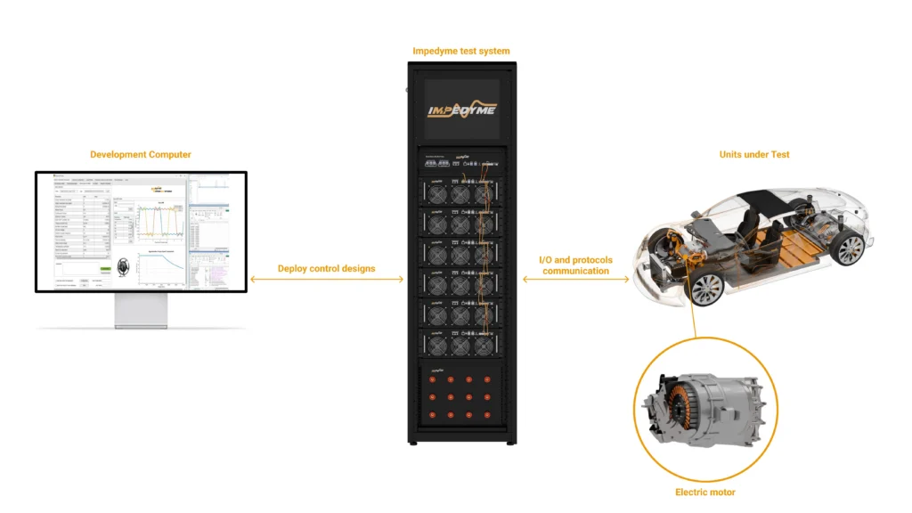
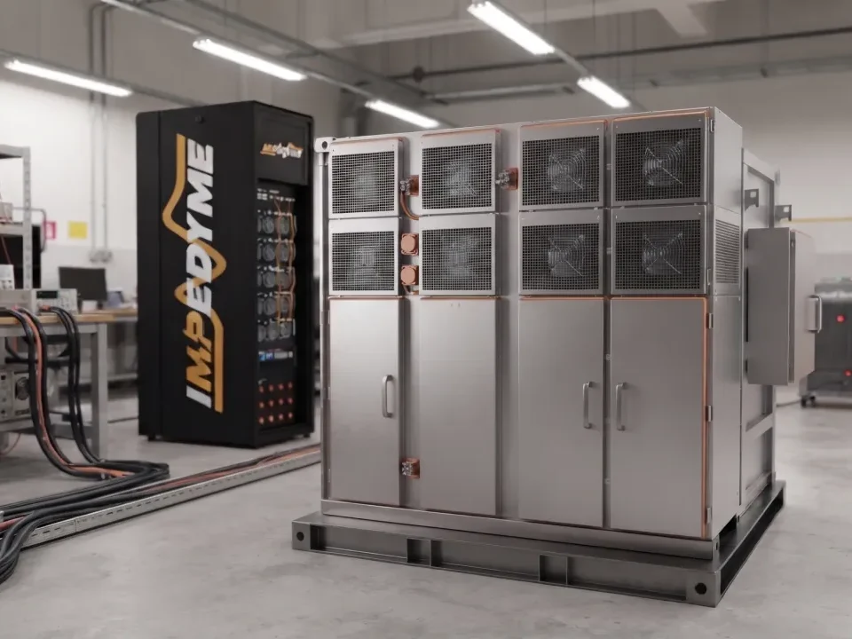
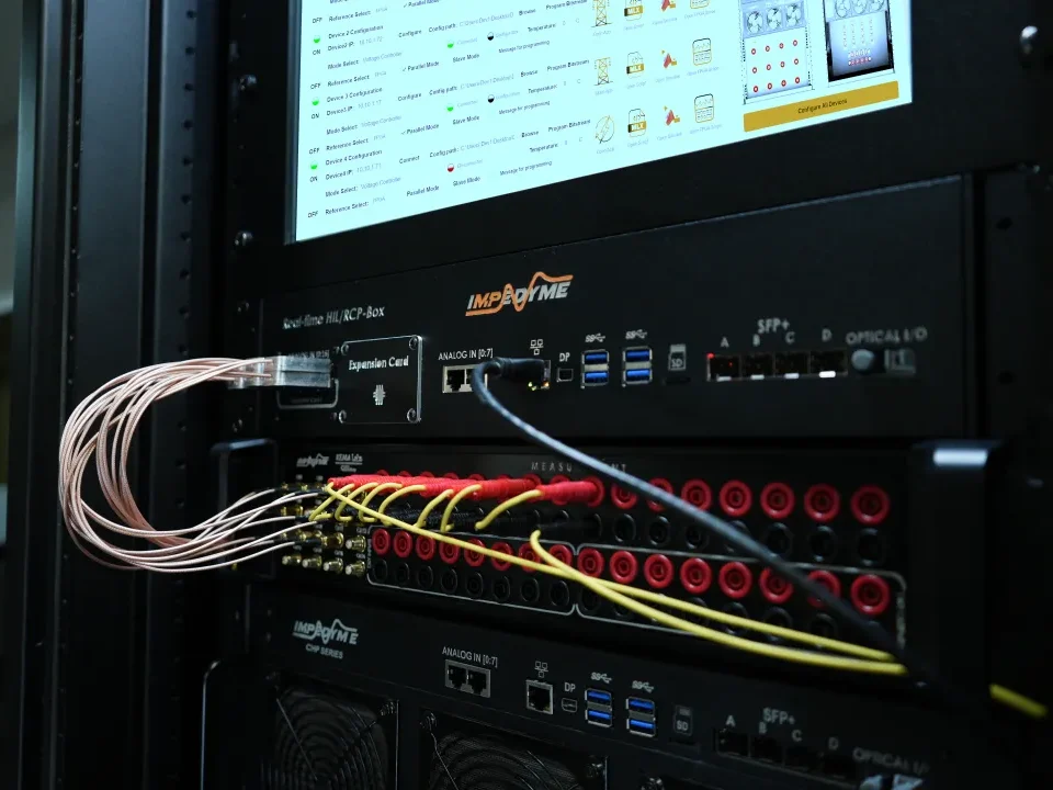
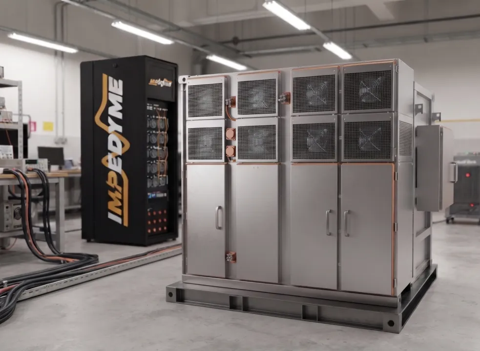
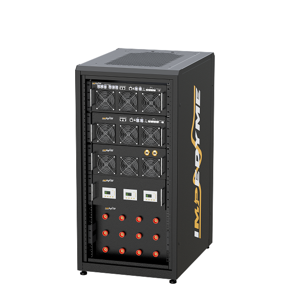
接下来,嵌入式控制器成为被测设备。电机和逆变器模型被部署到基于 FPGA 的实时目标机上——一台 Impedyme CHP 系列系统 率/限 HIL/RCP-Box ——运行 MotorSim Studio。控制器运行其真实固件,并以微秒级时间步长与虚拟电机进行闭环交互。
最后,测试进入功率领域。 Impedyme 的 PHIL 能力增加了一个再生功率接口——一个与 FPGA 实时内核协同设计的高带宽功率放大器——它将被仿真的电机转化为真实的电流和电压。此时,一台实体逆变器由一个提供并吸收真实功率的仿真电机驱动,无需任何实体电机或测功机。这里正是验证元件应力、热特性和全功率保护之处。
为使概念具体化,来看一个具有代表性的 PMSM 驱动器控制器 HIL 测试,并将其一般化到 Impedyme 生态系统中。
被测设备是一台运行磁场定向控制算法的嵌入式电机控制器。它连接到一台 Impedyme CHP 系列实时目标机,而非真实的电机和逆变器。闭环的工作方式如下:
From the controller’s perspective, a real motor is spinning. Engineers watch it command a speed, see the virtual motor accelerate, and observe balanced three-phase currents develop — all on screen, with no rotating mass anywhere in the lab.
A disciplined HIL test starts from named requirements and ends with numeric checks. In this walkthrough, two example requirements illustrate the idea:
Each requirement maps to a test case with defined initial conditions, stimulus, and pass criteria. When the automated test runs, it verifies the requirement and records the result, creating the traceable evidence chain that validation and certification teams need.
One of the most important decisions in motor control HIL is how to model the inverter. There are two fundamentally different approaches, and choosing correctly determines whether your test reveals real behavior or hides it.
车 averaged (ideal) inverter model represents the inverter using controlled voltage sources that reproduce the average behavior over a PWM period. It is computationally cheap and runs comfortably on a CPU at relatively coarse time steps. It is excellent for validating slow dynamics — speed loops, DC-bus energy balance, system-level coordination — where the fine detail of switching is irrelevant.
功 switching-level inverter model represents each semiconductor switch explicitly. It reproduces the actual on/off transitions, and therefore the current ripple, torque ripple, dead-time distortion, and switching harmonics that a real inverter produces. This detail is essential when you are developing the control for the inverter itself, or when protection logic trips on instantaneous peak currents rather than filtered averages. The catch is that it demands a very small time step — which is exactly why an FPGA is required.
| Attribute | Averaged (Ideal) Inverter Model | FPGA Switching-Level Inverter Model |
|---|---|---|
| Switch representation | Controlled voltage sources (averaged) | Each semiconductor modeled explicitly |
| Typical execution | CPU, coarse time step | FPGA, sub-microsecond time step |
| Current ripple visible? | No — muted by averaging | Yes — reproduced faithfully |
| Torque ripple visible? | No | Yes |
| Switching harmonics / EMC insight | No | Yes |
| Instantaneous peak-current faults | Missed | Captured |
| Best for | Speed loops, system-level dynamics | Inverter control, protection, ripple, EMC |
| Computational cost | Low | High (requires FPGA parallelism) |
An averaged model on a CPU will slow down until ripple and peak currents are muted, and hardware protection that would trip on a real bench misses the same trigger in simulation — leaving teams tuning around a simulator artifact instead of a real control issue. The FPGA solves this because it co-locates computation and I/O on the same chip, eliminating bus-transfer latency.
In an Impedyme FPGA-based real-time target, PWM gate edges are captured at nanosecond-scale resolution — on the order of a few nanoseconds — while the motor and inverter model updates at approximately one microsecond, driven by an FPGA clock running at roughly 200 MHz. Impedyme’s CHP platform pushes model updates as fast as 90 nanoseconds, performing hundreds to over a thousand updates per electrical period. That temporal resolution is what allows the emulated motor to reproduce saturation, cross-coupling, torque ripple, and back-EMF harmonics faithfully.
The stakes are quantitative. Impedyme notes that a 25-microsecond simulation loop reproducing an 8 kHz PWM can introduce up to 20% error, while sub-microsecond time steps cut that error to under 1%. In motor control, that difference is the line between a test you can trust and one you cannot.
Once the switching-level model is running, engineers can use Impedyme FPGA Scope to observe the signals that matter. FPGA Scope is a built-in, high-speed visualization tool embedded directly in the real-time signal path, capable of monitoring up to 16 simultaneous channels — phase currents, dq-axis currents, phase voltages, PWM edges, and internal controller states — at sub-microsecond resolution, without any external oscilloscope or DAQ hardware.
With the switching model, current ripple appears as the small high-frequency oscillation superimposed on the fundamental current waveform. This ripple is a direct consequence of the PWM switching acting on the motor’s winding inductance. It drives torque ripple, which in turn causes noise, vibration, and additional losses.
Engineers can run harmonic analysis on the captured waveforms to quantify the distortion and understand its spectral content — critical for anticipating electromagnetic compatibility (EMC) problems before they show up in an EMC lab. The high-frequency content that a switching-level model reveals is precisely the content that averaged models delete by construction, and precisely the content that determines EMI behavior.
A classic mitigation is to raise the PWM switching frequency. Current ripple is inversely proportional to switching frequency: increasing the frequency shortens the interval over which current can drift between switching events, so the ripple shrinks. This inverse relationship is well established — as an illustrative example, a CERN technical report on high-precision power converters notes that raising switching frequency “from 5kHz that is currently used, up to 60kHz and beyond … gives an increase in accuracy by an order of magnitude or more.” Raising a drive’s PWM frequency to 20 kHz — above the audible range — reduces current ripple, smooths torque, lowers audible whine, and cuts harmonic content, at the cost of higher switching losses.
Because HIL makes this a software change rather than a hardware rebuild, engineers can sweep the PWM frequency, observe the improvement in ripple and harmonics in real time on FPGA Scope, and find the optimal trade-off between ripple, losses, and thermal stress — all in a single afternoon.
Some of the most valuable HIL tests are the ones you could never safely run on real hardware. Fault-injection HIL is built to answer one question: what does the controller do when conditions break normal limits?
For a PMSM drive, the critical fault scenarios include short circuits in the inverter legs, phase loss, DC-link collapse, overcurrent events, over-speed, and sensor failures. On a physical bench, forcing a short circuit through an inverter leg stresses devices, varies run to run, and risks catastrophic damage. In HIL, the same fault is a scripted, perfectly repeatable event.
| Fault Scenario | What It Tests | Why HIL Is Superior |
|---|---|---|
| Inverter leg short circuit | Overcurrent protection, shoot-through response | Destroys real hardware; safe and repeatable in HIL |
| Overcurrent event | Current-limit and trip thresholds | Precise, timed injection without device stress |
| Phase loss / open circuit | Fallback and ride-through logic | Hard to stage physically; trivial in simulation |
| DC-link voltage sag | Low-voltage restart and control margin | Dangerous at power; deterministic in HIL |
| Over-speed | Speed-limit enforcement | Risk of mechanical failure on real motor |
| Sensor / resolver fault | Fault detection and safe-state entry | Repeatable at exact timestamps |
A typical scripted scenario shows the power of the approach: the test runs normally, then at exactly 5 seconds a short-circuit fault is injected. The controller’s protection logic should detect the overcurrent and shut off the PWM within its specified response time. Because the fault triggers on a timestamp and the plant is deterministic, the test verifies not only that protection fires, but that it fires fast enough and recovers cleanly — every single run.
This is impossible or prohibitively dangerous with real hardware, but straightforward and safe with HIL. It is one of the strongest arguments for adopting HIL testing for electric motor control.
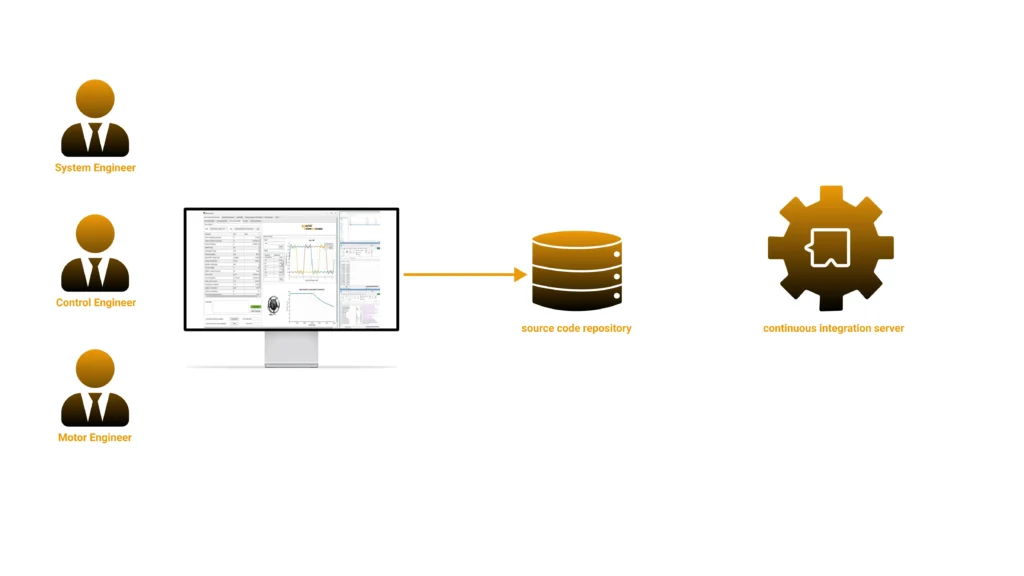
The final piece of the workflow is automation. Once a HIL bench is safe and deterministic, motor control testing can join the same continuous-integration (CI) practices that software teams have used for decades — something that was traditionally impossible for power electronics because lab testing was too slow and expensive to run on every code commit.
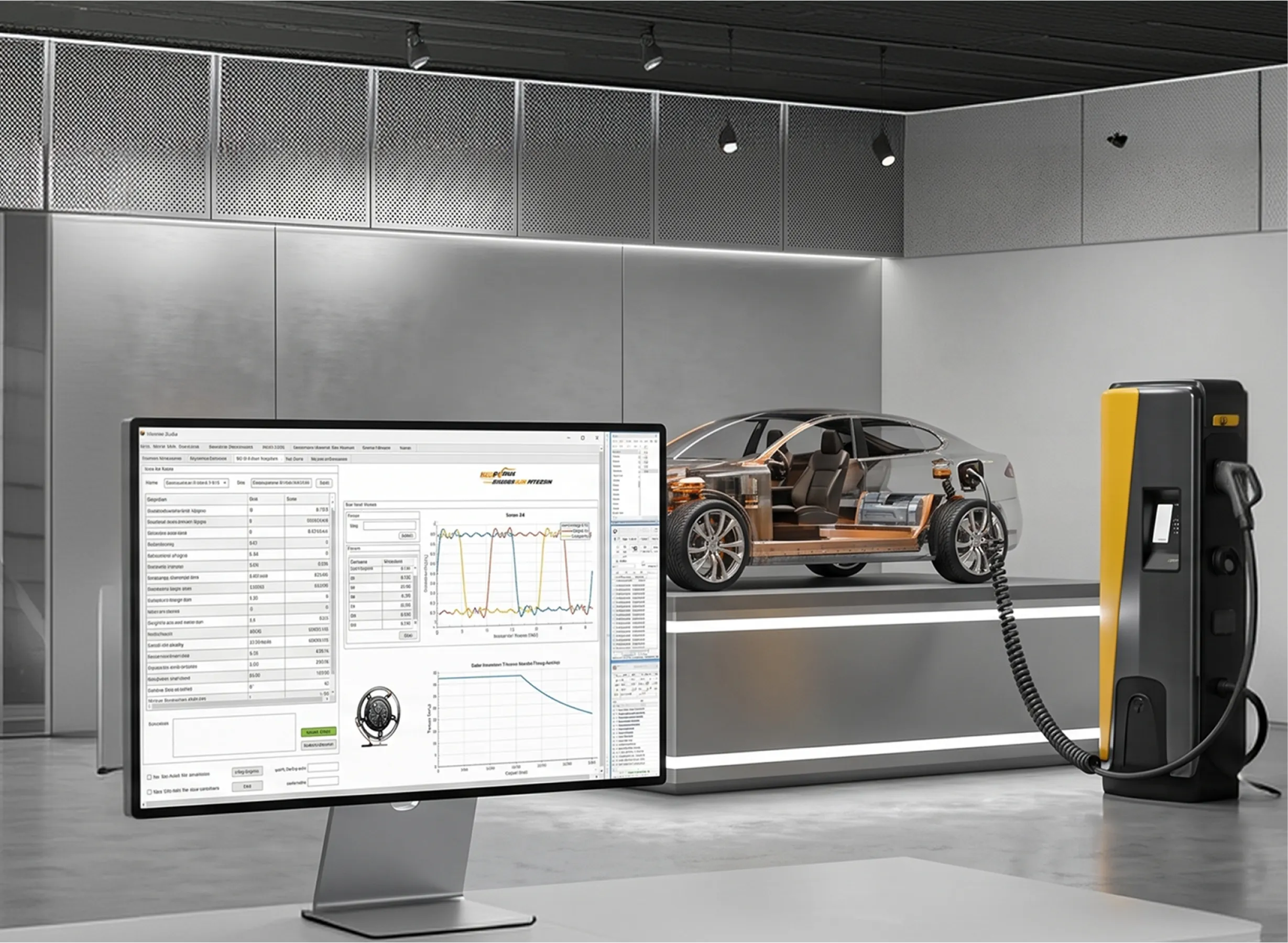
借助 Impedyme PowerHIL Studio orchestrating the bench, engineers can build automated test campaigns using a scenario and sequence editor: drive cycles, ramps, step changes, and fault scenarios, with automated pass/fail criteria and reporting of key metrics such as current ripple, torque ripple, efficiency, and protection response. PowerHIL Studio also enforces built-in safety and limit management with configurable current, voltage, and power limits and controlled shutdown.
A mature motor control CI workflow looks like this:
Because the tests are scripted and the bench is safe, the whole suite runs unsupervised. Test execution that once took weeks in a power lab can complete in under an hour, and the same test assets remain valid from the earliest signal-level testing through full-power PHIL validation.
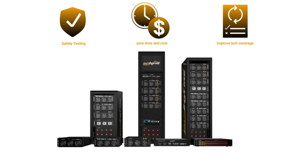
What makes this workflow seamless is that Impedyme delivers every piece as an integrated ecosystem, so models and test assets flow from desktop simulation to full power without being rewritten.
Together these components enable Combined Hardware-in-the-Loop and Power (CHP) testing, letting engineers validate control logic and power electronics simultaneously.
This same platform extends naturally to adjacent validation challenges. Teams working on motor control HIL often also need BMS HIL testing for battery management systems, full EV powertrain HIL for system-level validation, and inverter testing at full traction power — all of which run on the same CHP Series hardware and software ecosystem.
A common question is when to use each testing stage. The answer is that they are complementary, not competing, and the right program uses all of them in sequence.
| Method | Fidelity | Cost & Safety | Best Use |
|---|---|---|---|
| Desktop simulation | Model-level only | Lowest cost, no risk | Algorithm design, early logic checks |
| Controller HIL (signal) | High timing fidelity, no power | Low cost, very safe | Firmware, protection logic, fault injection |
| 功率 HIL(PHIL) | Full electrical fidelity at power | Moderate cost, safe (emulated) | Power-stage stress, thermal, full-power protection |
| 测功机 | Full mechanical fidelity | High cost, real hazards | Final system validation, efficiency mapping |
The guiding principle is to start at the signal level early, move to PHIL for power-stage and envelope coverage once the power stage is available, and reserve the dynamometer for final mechanical validation. Making FPGA-based, microsecond-or-faster time-step fidelity a hard requirement ensures that coarse simulation never misrepresents switching behavior along the way.
Based on the workflow above, here is a staged, actionable path — and the benchmarks that should govern each decision.
HIL testing for electric motor control has evolved from a nice-to-have into the central gate for validating PMSM drives. It lets engineers test safely, test earlier, iterate faster, ensure compliance, isolate the controller, and automate coverage of edge cases that no physical bench could safely reproduce. The key enabler is FPGA-based real-time simulation, which alone can reproduce the switching-level ripple, torque ripple, and fault behavior that determine whether a drive is genuinely ready for production.
Impedyme brings the entire workflow — desktop simulation, controller HIL, and full-power PHIL — into one integrated ecosystem built around the CHP Series, MotorSim Studio, PowerHIL Studio, FPGA Scope, RCP-Box, and Impedyme-RT. The result is faster development, safer validation, and higher-fidelity results from the first line of control code to the final full-power test.
What is HIL testing for electric motor control?
HIL (hardware-in-the-loop) testing for electric motor control is a real-time simulation method in which an embedded motor controller runs its real software while interacting with a virtual PMSM and inverter running on a real-time target. The controller sends PWM commands and receives simulated currents and rotor position, forming a closed loop that behaves like a real motor drive without any physical motor.
What is the difference between an averaged and a switching-level inverter model?
An averaged inverter model represents the inverter with controlled voltage sources and captures only average behavior, making it cheap to run but blind to ripple and switching harmonics. A switching-level model represents each semiconductor switch explicitly, reproducing current ripple, torque ripple, and harmonics — essential for inverter control development, protection testing, and EMC analysis. Switching-level models require FPGA execution.
How does HIL testing handle inverter fault injection?
HIL lets engineers inject faults such as inverter-leg short circuits, phase loss, overcurrent, DC-link sag, and over-speed as scripted, perfectly repeatable events. For example, a short circuit can be triggered at exactly 5 seconds to verify that the controller’s overcurrent protection shuts off the PWM within its specified time. These tests are dangerous or impossible on real hardware but safe and repeatable in HIL.
Can motor control HIL testing be automated for continuous integration?
Yes. With PowerHIL Studio, test campaigns can be scripted with automated pass/fail criteria, compared against desktop simulation baselines within defined tolerances (such as 10%), and triggered automatically when developers commit new firmware. This brings continuous integration and regression testing to power electronics, reducing test cycles from weeks to under an hour.
What is the difference between HIL and Power HIL (PHIL) for motor drives?
Controller HIL tests the embedded controller at the signal level against a virtual motor, with no real power flowing. Power HIL (PHIL) adds a regenerative power interface so real voltage and current flow between an emulated motor and a physical inverter, enabling full-power validation of the power stage without a physical motor or dynamometer.
Which Impedyme products are used for PMSM controller HIL testing?
PMSM controller HIL testing on the Impedyme platform uses the CHP Series or RCP-Box FPGA-based real-time targets, MotorSim Studio for high-fidelity motor emulation, PowerHIL Studio for test orchestration and automation, FPGA Scope for sub-microsecond signal monitoring, and Impedyme-RT to connect model-based design tools to the hardware.