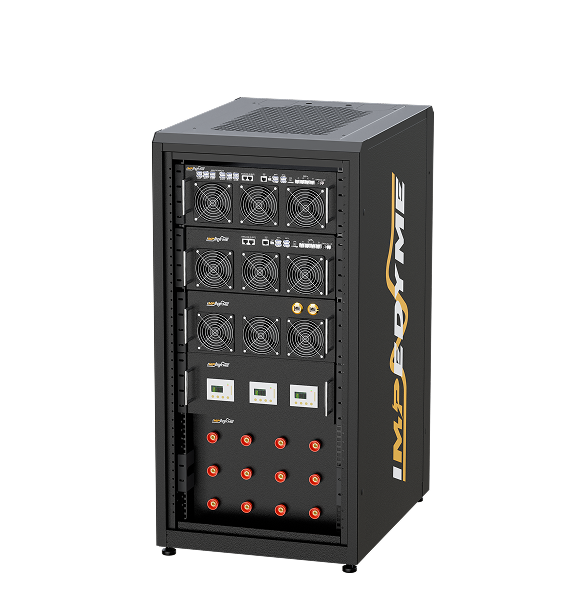

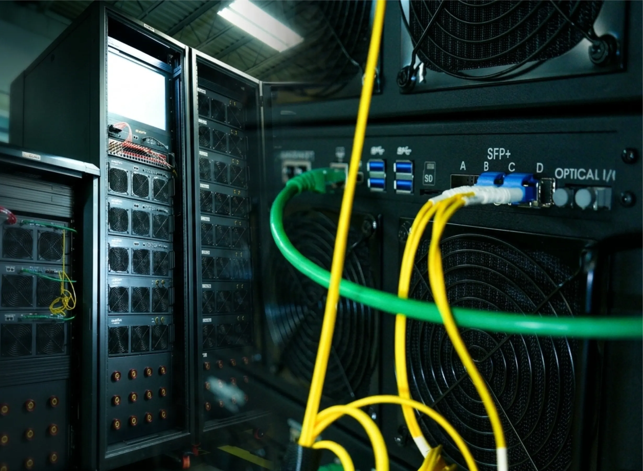
sfp module card
SFP Module header

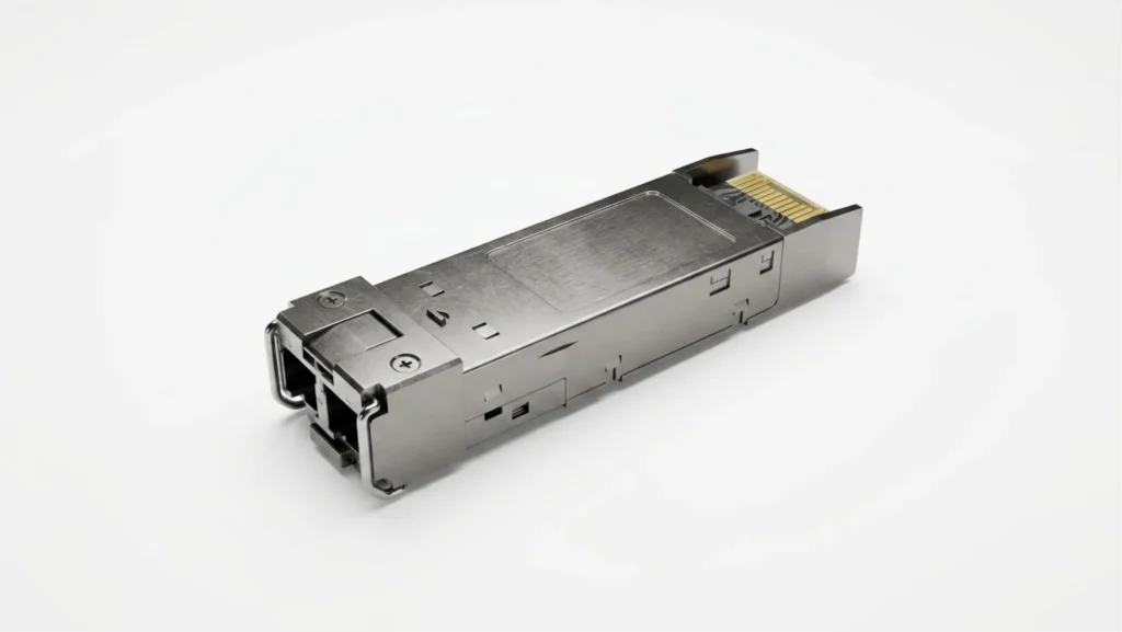
SFP Module

目录

SFP module technology is the quiet backbone of nearly every modern network and high-speed test system, and this guide explains it end to end. An SFP module — short for small form-factor pluggable, and known formally as a small form factor pluggable transceiver — is a compact, hot-swappable SFP transceiver that plugs into a host SFP interface to convert electrical signals into optical or copper signals and back again. In these pages we cover every practical dimension an engineer needs: the many SFP types, from the copper SFP (1000BASE-T RJ45) to the single-mode and multimode SFP fiber module; the jump from 1G SFP to SFP+ and the 10Gb SFP module class and beyond; how to choose, install and verify a module; a component-by-component teardown of what is inside; the connectors and mechanics of the SFP physical interface; compatibility and vendor coding; the bale-clasp color code; how SFP modules work; and a detailed SFP transceiver reference. We also introduce Impedyme’s own 12 Gb SFP module and its role in FPGA-based real-time simulation.

What Is an SFP Module?

SFP stands for Small Form-factor Pluggable, and the device is often written out in full as a small form factor pluggable transceiver. It is a self-contained transceiver — a transmitter and a receiver packaged together — that plugs into a standardized slot on networking and test equipment. The form factor is defined by a Multi-Source Agreement (MSA) originally captured in the SFF Committee document SFF-8074i, so that modules and host ports from different manufacturers share the same mechanical envelope, card-edge connector and management interface.

Engineers frequently blur three related but distinct things. It is worth keeping them separate:

  • The SFP module (also called an SFP transceiver, optical transceiver module, or historically a mini-GBIC) is the removable device you hold in your hand. It contains the laser or copper PHY, the receiver, the driver and amplifier electronics, and an identity/diagnostics chip.
  • The SFP port is the slot on the host device. Strictly, it is a metal cage soldered to the host board plus the electrical connector at the back of that cage. The module slides into the cage.
  • The SFP interface is the electrical and management boundary between module and host: the high-speed serial (SERDES) lanes that carry data, plus the low-speed two-wire serial management bus and control pins. The interface is what makes any compliant module work in any compliant port.

The name “mini-GBIC” survives from the earlier, larger GBIC (Gigabit Interface Converter) modules that SFP replaced; an SFP delivers the same function in roughly half the space, which is why it displaced GBIC almost completely.

SFP Module Types

The more useful way to understand SFP types is to organize them along four independent axes — media, speed, transmission mode/wavelength, and application — because a single SFP module is described by one choice on each axis, even though every variant presents the same SFP interface to the host.

SFP Types by Media

  • SFP fiber module — multimode (MMF): Uses inexpensive 850 nm optics over larger-core fiber (OM2/OM3/OM4) for short reaches inside a building or data center.
  • SFP fiber module — single-mode (SMF): Uses 1310 nm or 1550 nm optics over 9 µm-core fiber for reaches from a few kilometers to tens of kilometers.
  • Copper SFP (1000BASE-T): Terminates in an RJ45 jack and runs Gigabit Ethernet over twisted-pair copper for roughly 100 m. Ideal where a cable plant is already copper.
  • DAC (Direct Attach Copper) and AOC (Active Optical Cable): These are not swappable optics but fixed cables with the connector body permanently attached at each end — DAC for very short in-rack links, AOC for longer intra-facility runs.

SFP Types by Speed

  • 100M SFP (100BASE-FX/BX) for legacy fast-Ethernet fiber links.
  • 1G SFP, the classic Gigabit Ethernet module (SX/LX/ZX/T).
  • SFP+, the 10Gb SFP module class, defined electrically by SFF-8431 with a 10GBASE-R serial line rate of 10.3125 Gbaud.
  • SFP28, a 25G-per-lane evolution (25GBASE-R) running at 25.78 Gbaud.
  • SFP56, a 50G-per-lane SFP module using PAM4 signaling.
  • QSFP / QSFP+ / QSFP28 / QSFP-DD / OSFP are the “quad” relatives — physically larger cages carrying four or eight lanes to reach 40G, 100G, 400G and beyond. They are not SFP-compatible but share the same design philosophy.

SFP Types by Transmission Mode and Wavelength

  • SX — 850 nm multimode, short reach.
  • LX / LX10 — 1310 nm single-mode; LX is the 5 km IEEE variant, LX10 the 10 km commercial variant.
  • EX — 1310 nm single-mode extended reach (~40 km).
  • ZX — 1550 nm single-mode, ~70–80 km (an MSA/vendor spec, not IEEE-ratified).
  • BX / BiDi — single-fiber bidirectional optics that send and receive on two different wavelengths over one strand.
  • CWDM — Coarse Wavelength Division Multiplexing, 18 channels on a 20 nm grid from 1270–1610 nm.
  • DWDM — Dense Wavelength Division Multiplexing, many tightly-spaced channels for high-capacity long-haul.

SFP Types by Application

  • Enterprise / data center: high-density SX/SR and LR optics, DAC/AOC for top-of-rack.
  • Telecom / service-provider access: BiDi, CWDM/DWDM and long-reach ZX for fiber-to-the-x and metro links.
  • Industrial Ethernet: extended-temperature, ruggedized modules built to survive vibration and −40 °C to +85 °C environments.
  • Fibre Channel / storage: SAN-rated modules at 8G/16G/32G speeds.
  • Test & measurement / FPGA real-time systems: high-speed serial optics driven directly by an FPGA’s multi-gigabit transceivers, where determinism and isolation matter more than protocol overhead, with the SFP interface carrying those serial lanes straight from the fabric.

StandardWavelengthFiber typeTypical reach
1000BASE-SX850 nmMultimode~550 m (OM2); ~220 m on legacy 62.5 µm
1000BASE-LX1310 nmSingle-mode5 km (IEEE 802.3)
1000BASE-LX101310 nmSingle-mode10 km (commercial variant)
1000BASE-ZX1550 nmSingle-mode~70–80 km (MSA/vendor, fiber-grade dependent)
1000BASE-TN/A (copper)Cat5e/6 RJ45~100 m
10GBASE-SR850 nmMultimode~300 m (OM3); ~400 m (OM4)
10GBASE-LR1310 nmSingle-mode10 km
10GBASE-ER1550 nmSingle-mode40 km
10GBASE-ZR1550 nmSingle-mode~80 km (vendor/non-IEEE)

Why the SFP Module Is Important

The value of the SFP module is that it decouples the host device from the physical medium. A switch, router or simulator ships with generic SFP ports; the engineer decides, per port, whether that port becomes multimode, single-mode short reach, single-mode long haul, or copper — simply by choosing the module.

That modularity delivers several concrete benefits:

  • Media flexibility on one host port: the same port can run copper today and 40 km single-mode tomorrow.
  • Incremental upgrades without replacing the host: move from 1G to 10G by swapping optics rather than performing a forklift chassis replacement.
  • Cost control and second-sourcing: because the form factor is an MSA, modules can be sourced from more than one supplier, improving pricing leverage and supply resilience.
  • Simplified sparing and field repair: a failed link is fixed by hot-swapping a small, inexpensive module instead of returning the whole host.
  • Distance flexibility: the same host supports in-rack DAC and cross-campus fiber depending only on the module fitted.
  • Electrical isolation with fiber: an optical SFP breaks the copper ground path between endpoints, which is critical in high-voltage and noisy environments.

Without SFP, engineers would be stuck with fixed-media ports: separate hardware SKUs for every medium and speed, over-provisioned equipment purchased “just in case,” and expensive whole-unit replacements every time requirements changed.

SFP module impedyme

How to Choose an SFP Module

Choosing the right SFP module is a matter of answering a short sequence of questions in order. Because the SFP interface itself is standardized, every decision below is about the optics and the coding rather than the slot

Choose a Copper SFP or an SFP Fiber Module?

Choose a copper SFP when the run is under ~100 m, when you already have a twisted-pair cable plant, and when up-front cost is the priority. Copper draws more power per port and offers no electrical isolation. Choose an SFP fiber module when you need distance beyond 100 m, immunity to electromagnetic interference (EMI), galvanic isolation between endpoints, or lower per-port power at higher speeds. In high-voltage test benches, fiber’s isolation is often the deciding factor rather than distance.

Choose SFP or the Advanced SFP+?

An SFP+ port is the 10Gb SFP module class; a 1G SFP is the Gigabit class. Most SFP+ host ports are backward compatible and will accept a 1G SFP (usually running it at 1G), but the reverse is not true — a 1G-only port will not run an SFP+ module at 10G. Choose 10G when aggregate traffic, storage, or uplink demand justifies it; stay at 1G for edge access ports. The next steps up are SFP28 (25G) and SFP56 (50G PAM4) when roadmap capacity warrants.

Choose an MSA-Compatible SFP or Not?

Host equipment reads a small EEPROM in each module to identify it, and some hosts only enable ports for modules whose EEPROM carries a matching vendor ID. “Coded” or “compatible” modules are programmed to satisfy that check. Vendor-original modules cost more but carry no interoperability risk; MSA-compatible modules cost far less and, when correctly coded, behave identically — the risk is that a host firmware update tightens the check. Always verify a module using host diagnostics (DDM/DOM read-out) after installation.

Other Factors

Confirm wavelength (both ends must match), fiber type and OM grade (OM3/OM4 for 10G multimode reach), connector (LC is standard for duplex fiber, RJ45 for copper), DDM/DOM support for monitoring, operating temperature range (commercial, extended or industrial), and simplex vs duplex (BiDi uses a single strand and must be paired correctly). Every one of these is stated on the SFP module datasheet and should be checked against what the host’s SFP interface supports before you order.

Checklist: speed → media → reach → wavelength → fiber/OM grade → connector → host coding/compatibility → DDM support → temperature class → simplex/duplex pairing.

About the Impedyme SFP Module

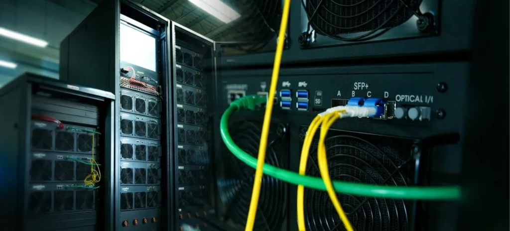
We build our own SFP module rated at 12 Gb, engineered specifically for the demands of FPGA-based real-time simulation rather than general enterprise networking. In a 真硬件在环(Hardware-in-the-Loop, HIL) 率/限 电力硬件在环(PHIL) system, the FPGA fabric contains multi-gigabit transceivers that can drive a serial optical link directly. A 12 Gb rating comfortably carries the high-speed, low-overhead serial protocols — such as Aurora — used to move sample data and control signals between chassis with minimal latency and jitter.

Three properties make an optical SFP link ideal here. First, determinism: a point-to-point fiber link driven by the FPGA carries data with predictable, bounded latency, which is essential when the simulation timestep is measured in microseconds. Second, galvanic isolation: because the link is optical, it breaks any ground loop between a controller and a high-voltage power stage — a safety and signal-integrity necessity on a PHIL bench. Third, noise immunity: fiber is unaffected by the switching transients that saturate copper in a power-electronics lab.

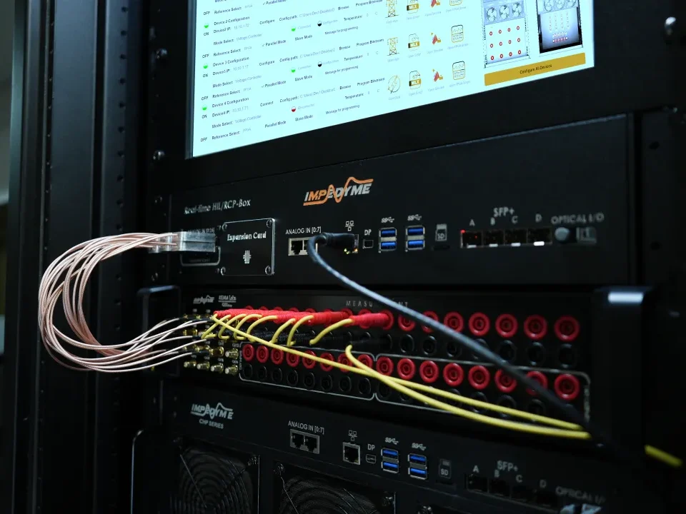
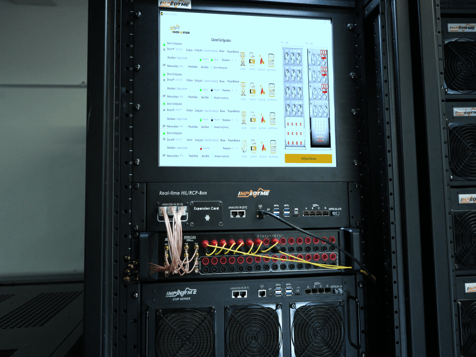
The 12 Gb SFP module fits alongside the rest of our platform: it provides chassis-to-chassis links between CHP Series real-time targets, connects an HIL/RCP-Box rapid-control-prototyping unit to the plant model, and carries the deterministic data that 型测试。 orchestrates. It underpins the workflows of PowerHIL Studio,, GridSim Studio, MotorSim StudioBatterySim Studio, where multiple simulation nodes must share state every timestep.

Where Is an SFP Port Located?

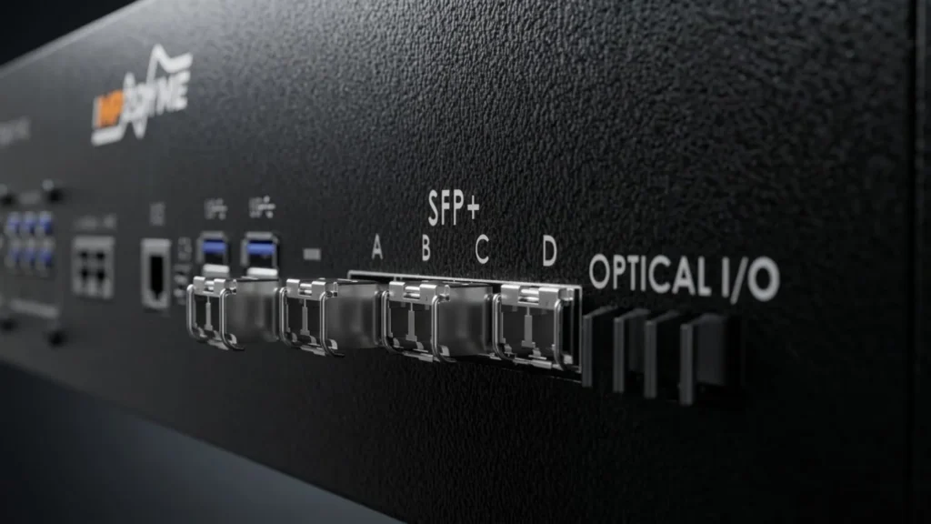
SFP ports appear anywhere a device needs flexible connectivity, since the port is simply the slot that accepts an SFP module. On a switch or router they usually sit on the front panel, often grouped as uplink ports at one end of the RJ45 bank, or as a full row on fiber-oriented switches; on modular chassis they populate line cards. Media converters typically pair one SFP cage with one copper port. Server and storage NICs and storage arrays expose SFP/SFP+ cages on their back panels. Industrial switches mount ruggedized cages on DIN-rail enclosures. Crucially for our audience, FPGA development boards and real-time simulator chassis carry SFP cages wired straight to the FPGA’s gigabit transceivers.

Visually, an SFP port is a rectangular metal cage roughly the width of an RJ45 jack but taller and deeper, with a slot rather than the eight gold contacts of an RJ45. Empty cages show a dark opening; a fitted SFP module protrudes slightly and carries a wire bale-clasp latch. Ports are usually numbered sequentially and labeled as uplinks; high-density hosts use stacked or ganged cages (two cages in one vertical housing) to double port density.

SFP port

What Is Inside an SFP Module?

This is where most guides stop short. Internally, an SFP module is a small but sophisticated opto-electronic assembly. Working from the electrical end to the optical end, the parts are: the electrical (card-edge) connectorPCBA (printed circuit board assembly) carrying the Laser Diode Driver ICPost Amplifier IC, and — often on the back side — the Digital Diagnostics IC; the Laser Diode TOSA (transmitter) and the PIN + TIA ROSA (receiver); and the optical connector receptacle. The whole assembly sits in a metal housing/shell.

TOSA (Transmitter Optical Sub-Assembly)

The TOSA converts electrical bits into light. At its heart is a TO-can (transistor-outline can) built as an assembly chain: a header provides the electrical feedthrough and mechanical base; a SiOB (silicon optical bench) precisely positions the chips; the LD chip (laser diode) mounted on its LD submount emits the light; a PD chip (monitor photodiode) on its PD submount samples a fraction of that light for power control; and a lens cap (with a window-caplens) seals and focuses the beam. That gives the TO-CAN ASSEMBLY = Header + SiOB + LD Chip + PD Chip + Cap.

The TO-can is then built up into the full TOSA ASSEMBLY = TO-Can + Isolator + Z-Bushing + Receptacle. An optical isolator blocks light reflected back toward the laser, which would otherwise destabilize it; a Z-bushing sets the precise axial (Z-axis) spacing for focus; and the receptacle — containing a fiber stub held by a split sleeve — accepts the external fiber connector. A key detail: the lens cap facet is angled at 8 degrees so that any light reflected off that surface is deflected away from the laser cavity rather than straight back into it, suppressing back-reflection that would add noise and jitter.

ROSA (Receiver Optical Sub-Assembly)

The ROSA does the reverse: it converts incoming light back into an electrical signal. A PIN photodiode turns photons into a tiny current, and an integrated transimpedance amplifier (TIA) converts and amplifies that current into a usable voltage. Receiver sensitivity — the weakest signal the module can reliably detect — is limited chiefly by the noise floor of the PIN/TIA combination; the quieter the TIA and the more efficient the photodiode, the further the link can reach for a given transmit power.

The Laser Diode Driver IC

This chip takes the host’s high-speed electrical data and modulates the laser current accordingly, switching the laser between its “0” and “1” light levels fast enough to keep pace with the line rate while holding a stable bias point and extinction ratio.

The Post Amplifier / Limiting Amplifier IC

On the receive path, the post amplifier (a limiting amplifier) takes the recovered signal from the TIA and squares it up into clean, constant-amplitude logic levels for the host SERDES, and typically generates the loss-of-signal (LOS) indication.

The Digital Diagnostics IC, EEPROM and MCU

Every SFP carries an EEPROM — its identity card — read by the host over a two-wire serial bus. Per SFF-8472, it stores vendor ID, part and serial numbers, supported wavelength, distance and data rate, and the live DDM (Digital Diagnostics Monitoring) data map. A small MCU and the Digital Diagnostics IC continuously measure module temperature, supply voltage, laser bias current, and transmit/receive optical power, exposing them to the host for real-time monitoring. Together these make an SFP module self-describing, so the host knows exactly what optics are fitted the moment the module seats in its cage.

PCBA, Connectors and Housing

The PCBA ties everything together electrically. The card-edge electrical connector mates with the host cage’s connector to carry the high-speed lanes, power and management pins. The optical connector receptacle presents an LC (or SC) interface to the outside world. The metal housing/shell provides EMI shielding — keeping the module’s high-frequency energy in and external noise out — and conducts heat away from the driver and laser. Together, those card-edge contacts and management pins form the SFP interface — the standardized electrical boundary that lets any compliant SFP module work in any compliant cage.

Signal flow: Transmit — host electrical data → card-edge connector → laser driver → TOSA laser → fiber. Receive — fiber → ROSA PIN/TIA → post amplifier → card-edge connector → host. Throughout, the diagnostics chip watches the module’s vital signs.

The Physical SFP Interface

The SFP physical interface has two sides: the optical/copper connector facing the cable plant, and the card-edge electrical connector facing the host.

  • LC connector: the dominant modern choice for duplex fiber — a small ferrule (1.25 mm) with two fibers (transmit and receive) in a compact latch. Nearly all current SFP fiber modules use LC.
  • SC connector: larger, with a 2.5 mm ferrule; common in the GBIC era and still found in legacy plant.
  • RJ45 interface: the copper SFP presents a standard eight-pin modular jack for twisted-pair.
  • MPO/MTP: multi-fiber push-on connectors used for parallel optics on QSFP modules, not standard SFP.
  • DAC/AOC: fixed-cable ends where the connector body is permanently attached.
  • Simplex single-fiber BiDi: a single LC bore carrying both directions on different wavelengths.

On the host side, the module’s gold card-edge fingers seat into the connector at the back of the SFP cage. A wire bale-clasp latch retains the module and, when flipped down, releases it. Because power and management are designed for it, modules are hot-swappable — inserted and removed while the host is powered, with the link renegotiating automatically.

Connector Comparison Table

ConnectorFerrule / typeFibersTypical use
LC1.25 mm2 (duplex) or 1 (BiDi)Modern SFP/SFP+ fiber
SC2.5 mm2 (duplex)Legacy/GBIC-era fiber
RJ458-pin modularCopper pairsCopper SFP (1000BASE-T)
MPO/MTPMulti-fiber8/12+Parallel optics (QSFP)
DAC/AOCFixed cableCopper/fiberShort in-rack links

SFP Module Compatibility

Compatibility has several layers, and all of them must line up.

  • Host-side coding: the host reads the module EEPROM and may enforce a vendor-ID match. Coded/compatible modules satisfy this; uncoded ones may be rejected on strict hosts.
  • Generation mixing: SFP+ ports usually accept 1G SFP modules, but 1G ports will not run SFP+ at 10G. SFP28 ports commonly accept SFP+ modules.
  • Fiber and wavelength matching: both ends of a link must use the same wavelength and compatible fiber type. A single-mode module will not interoperate with multimode fiber, and vice versa.
  • BiDi pairing: BiDi modules come as complementary pairs (for example 1310/1490 nm), and the two ends must be opposite types.
  • Speed negotiation: copper SFPs may auto-negotiate; some fiber links require fixed speed/duplex settings at both ends.

Troubleshooting checklist: confirm the port enables the module (no vendor-ID rejection); check that wavelengths and fiber types match at both ends; verify BiDi pairing; read DDM to confirm transmit power out and receive power in are within spec; and reseat the module and clean the connectors if receive power is low. On vendor lock-in: be honest that some hosts restrict third-party optics, and plan sourcing accordingly.

SFP Module Color Code

Manufacturers color the bale-clasp latch (and sometimes the pull tab) to signal wavelength and mode at a glance. This is a widely-followed convention, not a strict universal standard — colors can vary between suppliers, so always confirm from the module label and EEPROM data rather than color alone.

Bale/latch colorTypical meaning
Black850 nm multimode (SX / SR)
Blue1310 nm single-mode (LX / LR)
Yellow1550 nm single-mode (ZX / ER / ZR)
Purple / violet1490 nm (often BiDi downstream)
Greensometimes used for 1550 nm or copper, vendor-dependent
(Uncolored/black)Copper SFP (1000BASE-T), no wavelength

CWDM modules use a distinct per-wavelength color set across the 18-channel grid (1270–1610 nm in 20 nm steps). Because those assignments are vendor-specific, engineers should read the printed wavelength on the module rather than rely on the CWDM color chart.

How Do SFP Modules Work

End to end, an SFP module works like this. The host’s SERDES presents electrical data on high-speed serial lanes; that signal crosses the card-edge connector into the module. On transmit, the laser driver modulates the TOSA laser, launching light into the fiber. At the far end, the peer module’s ROSA captures the light with its PIN photodiode, the TIA amplifies it, and the post amplifier cleans it up before handing it back to that host’s SERDES.

Alongside the data path, the module manages itself. It recovers clocking from the data stream, asserts signal detect / loss-of-signal so the host knows whether a valid link is present, and exposes management over the two-wire serial interface. Because the interface supports it, modules hot-swap and links renegotiate automatically on insertion.

Finally, DDM/DOM reporting (per SFF-8472) continuously publishes temperature, supply voltage, laser bias current, and transmit and receive optical power. This is invaluable in practice: a slowly rising bias current warns of an aging laser, and a falling receive power flags a dirty or bending fiber — enabling predictive maintenance before a link actually fails.

SFP Transceiver 

SFP transceiver is a device class rather than a single product: any pluggable module that both transmits and receives on a serial link within the SFP mechanical and electrical envelope. The word itself contracts transmitterreceiver, and that duality is the entire point — one small form factor pluggable transceiver handles both directions of a link, so a single part number and a single slot deliver a complete bidirectional interface. Understanding the class means mapping its terminology across six independent dimensions: form factor, protocol, reach class, fiber count, wavelength plan, and the underlying laser and receiver technology. Specifying optics is really a matter of making one deliberate choice on each of those axes.

SFP Transceiver Types by Form Factor

The family runs from the legacy GBIC (larger, SC-connector), through SFP (1G), SFP+ (the 10Gb SFP module class), SFP28 (25G) and SFP56 (50G PAM4). The XFP was a separate, larger 10G form factor that SFP+ largely displaced by delivering the same rate in a smaller cage at lower power. The “quad” relatives — QSFP+ (40G), QSFP28 (100G), and the 400G-class QSFP-DDOSFP — carry four or eight lanes and are not SFP-compatible, but share the same pluggable, MSA-driven philosophy.

The single-lane SFP family remains the highest-volume pluggable class in the industry precisely because most links do not need four lanes: one serial stream, one pair of fibers, one cage. That density-versus-simplicity trade-off is why SFP cages still dominate access switches, industrial equipment and instrumentation, while quad form factors concentrate in data-center spine and aggregation roles.

SFP Transceiver Types by Protocol

SFP transceivers carry a wide range of serial protocols:

  • Ethernet — 100M, 1G, 10G, 25G and 50G, by far the largest deployment base.
  • Fibre Channel — storage-area networking across successive generations (roughly 1G through 32G class), specified against Fibre Channel rate steps rather than Ethernet ones.
  • SONET/SDH — telecom transport at OC-3/STM-1 (155 Mbit/s), OC-12/STM-4 (622 Mbit/s) and OC-48/STM-16 (2.5 Gbit/s).
  • CPRI and eCPRI — radio fronthaul between baseband units and remote radio heads.
  • Serial digital video (SDI) — broadcast transport, including the 3G, 6G and 12G-SDI tiers.
  • Lightweight FPGA serial links such as Aurora — a royalty-free link-layer protocol for high-speed serial communication over FPGA multi-gigabit transceivers, available in 8B/10B and 64B/66B variants. Aurora is why an SFP cage on a simulator chassis can become a deterministic inter-chassis link with almost no protocol overhead.

An important practical point most guides omit: the optics are largely protocol-transparent. An SFP module‘s job is to convert serial bits into light and back, so many SFP transceivers are rate-flexible within a supported range and are indifferent to what protocol the host layers on top. What must match is the line rate and the optical specification; the host defines the protocol. This is exactly what allows a standard SFP cage on an FPGA board to run a lightweight serial protocol instead of Ethernet.

SFP Transceiver Types by Reach Class

Reach classes are a shorthand for distance tiers, and the naming differs between the 1G and 10G generations even though the underlying idea is identical.

Reach classDesignation (1G / 10G)Fiber and typical reach
Short reachSX / SRMultimode — ~220–550 m (1G); ~300–400 m (10G)
Long reachLX, LX10 / LRSingle-mode — 5 km (LX); 10 km (LX10, LR)
Extended reachEX / ERSingle-mode — ~40 km
Ultra-long reachZX / ZRSingle-mode — ~70–80 km

One nuance worth stating plainly, because vendor pages routinely blur it: SR, LR and ER are IEEE-defined; ZR and 1G ZX are MSA or vendor specifications, not IEEE-ratified. Those long-reach figures are supplier claims that depend on fiber grade, splice count and connector quality — treat them as a starting point for a link-budget check, not a guarantee.

SFP Transceiver Types by Fiber Count

Duplex transceivers are the default: two fibers, one carrying each direction. BiDi (simplex) transceivers use a single strand, transmitting on one wavelength and receiving on another, with an internal filter separating the two. BiDi halves fiber consumption, which matters enormously when fiber is leased or a duct is full.

The critical rule with BiDi is pairing. Modules are sold as complementary A and B types — for example 1310 nm transmit / 1490 nm receive at one end, and the mirror arrangement at the other. Two identical BiDi modules will never link. Always order them as matched pairs and label which end is which.

SFP Transceiver Types by Wavelength Plan

  • Grey optics use a single standard wavelength (850, 1310 or 1550 nm) and are the everyday choice.
  • CWDM (Coarse Wavelength Division Multiplexing) uses 18 channels on a 20 nm grid spanning 1270–1610 nm — simpler, uncooled optics, moderate channel count.
  • DWDM (Dense Wavelength Division Multiplexing) packs many channels onto a tight ITU grid (commonly 100 GHz or 50 GHz spacing) for high-capacity, long-haul transport, using temperature-stabilized lasers.
  • Tunable DWDM modules can be set to any channel on the grid, which collapses dozens of sparing SKUs into one and is invaluable for operators holding spares.

Whichever plan you adopt, both ends of a link must run the same wavelength, so an SFP module ordered for one channel cannot substitute for another.

Inside the Transceiver: Laser and Receiver Technologies

The reach class you choose implicitly selects a laser and receiver technology, and that is what really drives cost, power draw and thermal behaviour. Competitor pages almost never explain this, yet it is the difference between an SFP module that suits a bench and one that does not.

Transmitter technologies:

  • VCSEL (Vertical-Cavity Surface-Emitting Laser) — 850 nm, multimode, low cost and low power. The workhorse behind virtually every SX and SR module.
  • Fabry–Pérot (FP) laser — 1310 nm, moderate cost, with a broader spectral output. Suits short-to-medium single-mode links.
  • DFB (Distributed Feedback) laser — emits a narrow, stable single wavelength, which is what makes long reach and dense wavelength plans possible. The standard for 1310/1550 nm long-haul and for CWDM and DWDM channels.
  • EML (Electro-absorption Modulated Laser) — a laser with an integrated modulator. Because directly modulating a laser at high rates over long distances introduces chirp that smears the signal, EMLs are used where high speed and long reach must combine, such as ER and ZR class optics.

Receiver technologies:

  • PIN photodiode + TIA — the standard receiver, sufficient for the great majority of short- and long-reach links.
  • APD (Avalanche Photodiode) — provides internal gain and therefore meaningfully better sensitivity, which is what enables extended and ultra-long reach classes. It costs more and requires a higher bias voltage.

SFP Transceiver Performance Parameters

These are the specifications engineers actually compare on an SFP module datasheet:

  • Data rate / line rate — must match what the host serialiser is configured to run.
  • Wavelength and spectral width — must match at both ends of the link.
  • Transmit optical power — quoted as a minimum and a maximum.
  • Receiver sensitivity — the weakest signal the SFP module can reliably recover.
  • Receiver overload (saturation) — the maximum light the receiver can tolerate. This is the most commonly overlooked parameter: fitting long-reach optics on a short patch link can saturate or damage the receiver, so an inline optical attenuator is required. If a brand-new long-reach link errors badly over a few metres of fiber, overload is usually the cause.
  • Extinction ratio — how cleanly the module distinguishes a light “1” from a dark “0”. Poor contrast erodes margin even when raw power looks healthy.
  • Link (power) budget — think of it plainly: the transmitter launches a certain amount of light; every kilometre of fiber, every connector and every splice removes some of it; the receiver needs a minimum amount to work. As long as what arrives stays above the receiver’s sensitivity, the link is healthy — and the DDM receive-power reading tells you exactly how much margin remains.
  • Dispersion penalty — chromatic dispersion limits long single-mode links (especially at 1550 nm), while modal dispersion limits multimode distance. This is why reach specifications are tied to fiber grade rather than being a single universal number.
  • Jitter and eye quality — timing stability of the recovered signal, which matters far more in deterministic and real-time systems than in best-effort networking.
  • Power consumption — drives both host power budgeting and module temperature.
  • Operating temperature class — see below.

SFP Transceiver Power Classes and Control Signals

The SFP+ specification defines module power levels, and hosts advertise how much power a cage can supply. Ordinary short-reach optics sit comfortably at the lowest level; high-power modules — long-reach ZR optics, DWDM and tunable modules — draw considerably more and need explicit host support plus adequate airflow. Fitting a high-power module into a cage or chassis that cannot cool it produces intermittent, temperature-correlated faults that are painful to diagnose.

Beyond the high-speed data lanes, the SFP interface carries a set of low-speed control and status signals:

  • TX_DISABLE — host command to shut the transmitter off.
  • TX_FAULT — module reports a transmitter fault.
  • RX_LOS — loss of signal on the receive side, the primary link-down indicator.
  • MOD_ABS — tells the host whether a module is physically present.
  • Rate select — switches receiver bandwidth on multi-rate modules.
  • SCL / SDA — the two-wire serial management bus used to read the EEPROM identity data and live DDM values.

Operating Temperature Classes

ClassTypical rangeWhere used
Commercial (COM)0 °C to +70 °CData centres, offices, climate-controlled rooms
Extended (EXT)−5 °C to +85 °CSemi-controlled enclosures, telecom cabinets
Industrial (IND)−40 °C to +85 °COutdoor cabinets, substations, factory floors, test benches near hot power stages

Exact extended-class ranges vary between suppliers, so confirm against the specific datasheet. For power-electronics laboratories the industrial class is usually the right default, because a rack sitting alongside converters and amplifiers runs far hotter than a server room.

SFP Transceiver Reliability, Aging and Lifecycle

Lasers age predictably. As a laser ages its threshold current rises, so the driver must push progressively more bias current to produce the same optical output. That makes DDM laser bias current the single best early-warning signal available — a slow upward trend tells you a module is nearing end of life long before the link actually drops. Falling receive power, by contrast, usually points at the fiber path: a contaminated end face, a bend, or a degrading splice.

Three practical habits extend module life: observe ESD precautions when handling, keep dust caps fitted and end faces clean, and give modules adequate airflow, since sustained high temperature accelerates laser aging. In critical systems, replace on trend rather than on failure — schedule the swap when the bias-current curve turns, not when the link goes down mid-test.

Coded, Uncoded and Programmable SFP Transceivers

Because every module carries an EEPROM identity, the market divides into modules coded for a particular host platform, uncoded/generic modules, and field-programmable modules that can be re-coded with a programmer. Programmable stock is genuinely useful for labs that maintain mixed equipment, since one shelf of modules can be coded on demand for whichever host needs it. The compatibility considerations and verification steps are covered in the SFP Compatibility section above.

Choosing an SFP Transceiver for FPGA-Based Real-Time Systems

Selection priorities shift substantially when the host is a real-time simulator rather than a switch:

  • Line rate must match the FPGA transceiver configuration, not a nominal Ethernet tier. The optics must cleanly pass whatever rate the multi-gigabit transceiver is set to run.
  • Jitter and latency determinism outrank throughput. A module that delivers headline bandwidth but adds variable delay is the wrong choice when the simulation timestep is measured in microseconds.
  • Galvanic isolation is a safety requirement, not a convenience. An optical link breaks the ground path between control electronics and a high-voltage power stage.
  • Industrial temperature class, because benches sit close to converters, amplifiers and loads that radiate significant heat.
  • DDM support, so that long unattended test campaigns can be monitored and a degrading link flagged before it corrupts a run.

Our 12 Gb SFP module is specified against exactly these criteria: sufficient rate headroom to carry lightweight serial protocols such as Aurora between chassis, while preserving the deterministic timing and electrical isolation that power-electronics validation demands.

Form-Factor Comparison Table

Form factorSpeed and lanesConnector
GBIC1G — single laneSC
SFP1G — single laneLC / RJ45
SFP+10G — single laneLC
SFP2825G — single laneLC
SFP5650G — single lane, PAM4LC
QSFP+40G — 4 lanes at 10GMPO / LC
QSFP28100G — 4 lanes at 25GMPO / LC
QSFP-DD / OSFP400G — 8 lanes at 50G, PAM4MPO

结论

The SFP module remains one of the most elegant ideas in networking and high-speed test: a small, hot-swappable small form factor pluggable transceiver that turns one generic SFP interface into any medium, speed or distance you need. Across the SFP types — the copper SFP for short copper runs, the single-mode and multimode SFP fiber module for reach and isolation, the SFP+ 10Gb SFP module class and the SFP28/SFP56 steps beyond — the same core principles of modularity, MSA interoperability, and rich DDM diagnostics apply. Whether you are building an enterprise fabric, a telecom access ring, or an FPGA-based real-time simulator, choosing the right SFP transceiver comes down to matching media, speed, wavelength, reach and compatibility to the job.

Frequently Asked Questions 

What is the difference between an SFP module, an SFP port and an SFP interface?

The module is the removable transceiver; the port is the cage-plus-connector slot on the host; the interface is the electrical and management boundary (high-speed serial lanes plus a two-wire management bus) between them.

What is the difference between SFP and SFP+?

SFP is the 1G class; SFP+ is the 10Gb class, defined electrically by SFF-8431 with a 10.3125 Gbaud line rate. Most SFP+ ports accept 1G SFP modules, but a 1G port cannot run an SFP+ module at 10G.

Can I use a copper SFP instead of fiber?

Yes, for runs up to about 100 m over twisted pair. Choose fiber instead when you need longer distance, EMI immunity, or electrical isolation.

How far can an SFP module transmit?

It depends on the type: multimode SX reaches around 550 m, single-mode LX/LR reaches 5–10 km, ER reaches 40 km, and ZX/ZR modules claim roughly 70–80 km (a vendor spec, not IEEE-ratified).

What is DDM/DOM on an SFP module?

Digital Diagnostics Monitoring (per SFF-8472) reports live temperature, supply voltage, laser bias current, and transmit/receive optical power, enabling predictive maintenance and troubleshooting.

What is an SFP fiber module used for in FPGA and test systems?

It provides deterministic, low-latency, electrically isolated serial links between chassis — often running lightweight protocols like Aurora over the FPGA’s multi-gigabit transceivers — which is ideal for HIL/PHIL power-electronics validation.