Battery cell testing card

应用知识电网电机产品知识网络研讨会

Battery cell testing header

电池电芯测试:标准与现代测试系统

Battery cell testing is the foundation of every safe, reliable, and high-performing battery product. Whether the destination is an electric vehicle, a heavy-lift drone, a grid-scale storage installation, or a consumer device, every battery pack is only as good as the individual cells inside it — and every cell must be measured, characterized, stressed, and validated before it earns its place in a product. A single weak or defective cell can compromise an entire pack containing hundreds or thousands of cells, which is why battery cell testing sits at the very start of the energy-storage value chain and never really stops, from R&D characterization through production end-of-line checks to second-life qualification.

本指南将说明电池电芯测试涉及哪些内容、工程师运行的六大类测试、规范车用电池电芯测试的标准、一套完整的电池电芯测试系统是什么样子,以及现代电池仿真与 电力硬件在环(PHIL) 技术——包括 Impedyme 的 BatterySim Studio 和 CHP Testbench 平台——正在如何变革工程团队验证电芯、电池管理系统和电力电子设备的方式。

什么是电池电芯测试?

电池电芯测试是对单个电化学电芯进行测量和应力测试的系统性过程,用以量化其容量、功率能力、效率、内阻、热行为、安全裕度和耐久性。电芯是任何电池系统中最小的功能单元,其行为决定了构建于其之上的一切的上限:模组、电池包、 电池管理系统(BMS),以及最终由其供电的车辆或设备。

测试的目的会因你处于产品生命周期的哪个阶段而不同:

  • 研发: 表征新的化学体系、电极设计和电芯规格;构建精确电芯模型所需的数据。
  • 设计验证: 确认候选电芯满足目标应用的能量、功率、寿命和安全要求。
  • 认证与合规: 在电芯出货或安装到车辆之前,证明其符合国际安全和运输标准。
  • 生产质量控制: 在下线环节、电芯进入模组和电池包之前发现制造缺陷。
  • 在役与二次利用评估: 测量健康状态(SOH),以支持保修决策、再利用和回收。

不同应用的利害关系各不相同,但学科方法是共通的。在电动汽车中,电池电芯测试为续航里程、快充能力、保修寿命和碰撞安全提供保障。在无人机和 eVTOL 飞行器中,电芯被推向远超汽车工况的极端放电倍率,因此测试必须同时验证高功率密度和在反复高应力脉冲下的存活能力。在固定式电网储能中,优先事项转向循环寿命、往返效率以及数千次循环中的低自放电。在消费电子产品中,重点是能量密度、密闭外壳中的安全性以及运输合规性。在所有这些领域,电池电芯测试都是将化学配方转化为合格、可认证、可靠可投资产品的关键。

为什么电池电芯测试很重要

锂离子电芯在很小的体积内储存了惊人的能量,而正是这种能量密度使得严格测试不容妥协。测试不足的后果会以三种方式显现:

安全性. 内部短路、锂析出、隔膜损伤和热滥用都可能引发热失控——一种自加速的放热反应,可导致排气、起火或爆炸。滥用测试的存在,正是为了精确表征电芯如何失效,并验证它能否尽可能平稳地失效。

性能与可靠性. 容量、内阻和效率因电芯而异,并随时间漂移。没有精确的表征,BMS 就无法正确估算荷电状态(SOC)或 SOH,电池包容量设计只能靠猜测,现场性能也会令人失望。

成本与上市时间. 电池开发项目的成败取决于测试吞吐量。老化测试要运行数月;滥用测试会毁掉昂贵的电芯;实验室中的安全事故会使整个项目停摆。测试速度、可重复性和安全性的每一项改进,都会直接转化为更快的开发周期和更低的成本。

battery management testing picture

电池电芯测试的六大类别

一套完整的电池电芯测试计划涵盖六个类别。每一类都回答一个不同的工程问题,而一场严肃的验证活动会涉及所有这些类别。

1. 电气特性表征

电气特性表征确立了电芯的基线电气指纹——每个模型、BMS 算法和电池包设计都依赖的数据。

容量和能量测试。 电芯在受控协议下充电(通常是恒流后接恒压,即 CC-CV),然后以规定的倍率放电至截止电压。将电流对时间积分得到以安时为单位的容量;乘以电压得到以瓦时为单位的能量。将实测容量与额定值比较以标记缺陷,而容量随时间的保持率是健康状态的主要定义。

开路电压(OCV)映射。 OCV 是电芯在无负载下松弛后的静置端电压。由于 OCV 与 SOC 相关,工程师通过让电芯以小幅充电或放电增量逐步变化、每步之间设置静置期,来构建 OCV 对 SOC 的曲线。这条曲线是基础性的:BMS 依靠它进行 SOC 估算,此处的任何误差都会传播到每一项下游计算中。

内阻和阻抗。 直流内阻(DCIR)通过施加电流脉冲并观察瞬时电压响应来测量;交流内阻(ACIR)则使用单一频率的小幅交流激励。内阻是退化最有力的早期指标之一——相对基线值的显著增长与容量衰减、功率损失和热风险上升高度相关。

电化学阻抗谱(EIS)。 EIS 在很宽的频率范围内——从毫赫兹区一直到数十千赫——施加小幅正弦激励,并记录复阻抗响应,通常以奈奎斯特图和伯德图可视化。由于不同的电化学过程在不同频率下响应,EIS 能够分离欧姆电阻、电荷转移电阻、双电层电容和扩散行为。它能检测到简单直流测量遗漏的细微老化特征,使其成为电池电芯测试中信息量最丰富的诊断手段之一。

混合脉冲功率特性表征(HPPC)。 HPPC 在连续的 SOC 点上施加结构化的放电和充电电流脉冲序列,通常在多个温度下重复进行。工程师从电压响应中提取等效电路模型(ECM)参数——串联电阻、极化电阻和时间常数——从而生成电阻和可用功率相对于 SOC 和温度的完整映射。这张映射正是 BMS 进行功率限值计算所需要的,也正是实时电芯模型进行精确仿真所需要的。

2. 性能测试

性能测试回答的问题是:电芯在真实且严苛的工况下表现如何?

  • 充放电循环 在规定协议下可重复地测量所输出的容量和能量,确立电芯的参考行为。
  • C 倍率测试 在不同的充放电倍率下评估电芯——例如 0.2C、0.5C、1C、2C 及更高。更高的倍率会暴露负载下的电压下垂、发热量增加以及与倍率相关的容量下降。对于放电脉冲可达额定容量极端倍数的无人机和 eVTOL 电芯而言,高倍率测试决定了一块推进电池是能够存活,还是在任务中途突然失效。
  • 效率测试 测量库仑效率(输出电荷除以接受电荷,健康的锂离子电芯通常高于 99%)和能量效率,后者总是更低,因为它计入了充放电之间的电压差,并随 C 倍率上升而下降。高精度的库仑效率测量还是一种强大且省时的长期耐久性预测手段——在几个循环中测得的微小低效,与原本需要数月循环才能观察到的退化高度相关。
  • 行驶循环与任务剖面测试 回放真实的负载剖面——城市行驶循环、快充事件、无人机爬升与悬停任务——以在电芯实际将经历的动态条件下对其进行验证。

3. 生命周期与老化测试

老化测试预测电芯能使用多久以及它将如何退化。退化通过两种相互耦合的模式发生:

  • 循环老化 源于主动使用。反复的锂嵌入和脱出会在电极中造成机械应力和颗粒开裂,而在高倍率或低温下充电会促使锂在负极上析出——金属锂沉积会消耗可循环的锂,在最坏情况下还会生长出能够刺穿隔膜的枝晶。
  • 日历老化 即使在静置状态下也会发生。主导机制是负极上固体电解质界面(SEI)层的持续生长,它会消耗锂库存。日历老化在高存储 SOC 和高温下会加速,这正是存储条件对车队和仓库物流如此重要的原因。

行业标准对寿命终点的定义是:电芯容量降至其初始额定值的 80%(或其功率能力降至原始规格的 80%)的那一点。循环寿命测试让电芯反复进行完整或部分循环,直至越过该阈值;而日历寿命测试则将电芯存储在受控的 SOC 和温度下,并定期中断存储以运行参考性能测试——容量、HPPC 和 EIS——来跟踪退化轨迹。由于实时老化需要数月到数年,加速老化协议、严谨的统计设计和退化建模是任何严肃的生命周期项目不可或缺的部分。

4. 环境测试

环境测试使电芯承受其将在现场遇到的气候应力,通常使用控制温度和湿度的环境试验箱,有时还结合海拔和振动:

  • 热循环 在极端温度之间——常见范围如 −40 °C 至 +85 °C——会暴露由反复膨胀和收缩引起的机械疲劳、密封退化和连接失效。
  • 极端温度特性表征 在高温和低温极限下测量容量和内阻。低温会急剧增加内阻以及充电时的锂析出风险;高温会加速所有退化机制并减小与热失控之间的裕度。
  • 湿度测试 评估潮湿环境中的腐蚀、绝缘击穿和短路风险。
  • 海拔和低气压测试 模拟航空运输和高海拔运行,是运输认证的必要环节。

5. 滥用与安全测试

滥用测试有意将电芯驱动到超出其安全运行极限,以表征失效行为并验证保护机制是否有效。这些测试具有破坏性,在配备排气、灭火和远程监控设施的加固测试单元中进行。它们分为三类:

  • 电气滥用: 过充、过放(强制放电至电压反向)和外部短路。这些测试探究电芯及其内部保护装置如何应对电气故障条件。
  • 热滥用: 热稳定性(热烘箱)测试、受控加热至热失控发生点,以及——对电池包设计至关重要的——热失控蔓延测试,用以表征失控事件是否以及如何从一个电芯蔓延到相邻电芯。
  • 机械滥用: 针刺(将导电钉穿过电芯以制造内部短路)、挤压、冲击和跌落测试,全部在精确定义的加载速率和力限值下进行,以便不同实验室和项目之间的结果具有可比性。

滥用测试的统一目标不是防止失效——在足够的滥用下,每个电芯都会失效——而是确保电芯尽可能安全地失效,不发生剧烈的热失控、起火或爆炸,并确保任何单电芯事件都能在电池包层面得到控制。

6. 机械与振动测试

振动和机械冲击测试验证电芯能否经受运输和运行中的动态载荷。电芯、模组或电池包被安装在振动台上——通常安装在环境试验箱内,以便叠加热应力——并以标准化的随机和正弦剖面在三个轴向上激励,同时持续监测电压、温度和机械完整性。所关注的失效模式是内部损伤、电接触丧失和密封破裂,任何一种都可能在后续使用中演变为安全问题。

结构机械完整性与界面应力动态

锂离子电芯是动态的机械系统。在充放电循环期间,随着锂离子在负极和正极的主体基质内嵌入和脱出,主体材料会发生体积变化,导致整个电芯结构的宏观膨胀和收缩。

运行中机械压力映射

为优化电接触、防止活性层分层并控制软包和方形电芯的厚度变化,电芯通常在机械压缩下集成到模组中。然而,这种外部压力分布不均可能加速容量衰减并导致局部失效。

工程师使用直接集成在温控软包电芯测试夹具内的超薄矩阵式压阻压力映射网格,可以在 运行中评估压力分布。这些研究揭示了关键的结构特性:

  • 局部高压集中(「热点」): 在没有柔性补偿层的情况下,压力图显示压缩力会集中在厚度略高的高度局部区域,例如集流体极耳与箔材焊接处以及内部卷芯折叠处。这些机械热点会经历加速的局部老化。引入柔性泡沫压缩垫(顺应层)可将力均匀地分布到整个电芯表面,从而缓解应力集中。
  • 硬件在环
    • 在恒容模式下, 使用刚性板将电芯锁定在固定厚度。当石墨在锂化过程中经历相变时,电芯的内部膨胀会导致机械压力动态波动高达 40%(例如,从 0% 荷电状态时的基线 0.9 MPa 到 100% 荷电状态时的 1.3 MPa)。
    • 在恒压模式下, 有源伺服驱动系统动态调节压缩板,将力分布稳定保持在 0.1% 以内,同时允许电芯厚度变化以适应内部膨胀。

下表总结了车用电池电芯测试中评估的恒容与恒压循环模式之间的关键权衡:

评估参数恒容模式恒压模式
物理约束锁定电芯厚度;外部压力可变。主动调节外部力;电芯厚度可变。
压力变化波动高达 40%(例如 LFP 电芯为 0.9 MPa 至 1.3 MPa)。在整个充放电循环中稳定保持在 0.1% 以内。
主要退化驱动因素满荷电状态下的高机械应力集中,导致粘结剂断裂和 SEI 开裂。宏观摩擦和层间移动,可能导致隔膜磨损。
测试用途复现标准汽车电池包中的刚性模组约束环境。测量活性材料的基本材料膨胀曲线和固态相变。

无损计算机断层扫描

为了在不破坏电芯的情况下检查内部结构对齐并识别制造异常,现代开发项目依赖高分辨率计算机断层扫描(CT)。该技术使用无损 X 射线成像来重建电芯内部结构的高度精细的三维模型:

  • Cylindrical Form Factors: CT imaging validates the concentric winding of active layers, electrode tab positions, safety vent integrity, and central core buckling risk under high expansion forces.
  • Pouch and Prismatic Form Factors: CT scans inspect the alignment of stacked layers, looking for “waviness” in the electrode coatings. These layer waviness defects can restrict regional ionic transport, leading to localized lithium plating, capacity loss, and internal short-circuit hazards over extended cycling.

Component-Level Mechanical Characterization

Comprehensive mechanical characterization is necessary to parameterize multiphysics finite element models of battery cells, ensuring that pack-level mechanical designs can withstand high-rate vehicle dynamics. These mechanical characterizations are performed across an operating temperature range of -80 °C to +250 °C to simulate absolute environmental and crash conditions :

组件Test SuitePhysical Metric Measured工程意义
Separators & Foil CollectorsUniaxial Tensile StrengthPeak tensile load, yield strength, and percentage elongation under tension using video extensometers.Prevents separator tearing and foil cracking during high-speed manufacturing winding and extreme pack-level vibration.
Active Coating Interfaces180-degree and 90-degree peel / Z-Direction TensileAdhesion and cohesion energy of the active material mixture on the current collector foil.Predicts electrode active layer delamination and binder fracturing caused by dynamic cycling and expansion.
Coated Electrodes2-Point & 3-Point BendingBending stiffness, flexural modulus, and localized structural failure boundaries.Informs mechanical models of jelly-roll deformation under impact and external crash forces.
Separator MaterialsPuncture ResistancePeak force required for a hemispherical probe to penetrate the polymer separator foil.Evaluates separator resistance to penetration by localized lithium dendrites or surface burrs on current collectors.
Electrode CoatingsHigh-Precision CompressibilityThickness displacement versus compressive stress, determining elastic and plastic deformation boundaries.Informs finite element modeling of cell expansion forces under constant volume constraints.
Inter-Cell ConnectionsTab and Terminal Shear / Weld StrengthUltimate shear force and weld interface failure energy under stress.Validates ultrasonic and laser weld integrity against vehicle-level shock and vibration profiles.

Vehicle Battery Cell Testing: Standards and Requirements

Vehicle battery cell testing is the most demanding and most heavily standardized branch of the discipline. Automotive cells must deliver high energy and power simultaneously, survive a decade or more of daily use, pass crash and abuse scenarios, operate from arctic cold to desert heat, and qualify for global transport. To manage that complexity, engineers navigate a layered landscape of international standards:

  • ISO 12405 — test specification for lithium-ion traction battery packs and systems, covering performance, reliability, and abuse, with separate parts addressing high-power and high-energy applications and safety requirements.
  • ISO 6469 — electrical safety requirements for electrically propelled road vehicles, including the rechargeable energy storage system.
  • UN 38.3 — the mandatory transport-safety qualification for lithium cells and batteries, comprising altitude simulation, thermal cycling, vibration, shock, external short circuit, impact/crush, overcharge, and forced discharge.
  • UL 2580 — safety evaluation of EV battery systems, covering the complete pack including cells, modules, thermal management, and BMS integration, with electrical, mechanical, and environmental abuse tests.
  • SAE J2464 — a widely referenced abuse-testing procedure for rechargeable energy storage systems, defining electrical, thermal, and mechanical abuse tests at cell, module, and pack level.
  • SAE J2380 — vibration durability testing for traction batteries.
  • IEC 62660 — the cell-level series for road-vehicle lithium-ion cells: performance and endurance testing in Part 1, reliability and abuse testing in Part 2.
  • GB/T standards — national requirements for major markets that include particularly stringent cell-level safety items such as nail penetration testing.

These standards are not interchangeable. They target different levels of integration — cell, module, pack, system, vehicle — and different priorities: performance versus abuse safety versus transport. A robust vehicle battery cell testing program begins by mapping every applicable requirement to the correct test level and building a traceable compliance matrix, because gaps discovered late in a vehicle program are extraordinarily expensive to close.

The Cell-to-Pack Validation Workflow

Vehicle battery validation proceeds in stages, and cell testing feeds every one of them:

  1. Cell qualification. Individual cells are characterized (capacity, OCV, DCIR, HPPC, EIS) and sample populations undergo safety, environmental, and lifecycle testing.
  2. Model parameterization. Cell characterization data is used to build and parameterize equivalent-circuit and electrochemical models — the mathematical core of both the BMS algorithms and any real-time emulation.
  3. Module validation. Cells are assembled into modules, where balancing behavior, thermal gradients, busbar performance, and inter-cell propagation are validated.
  4. Pack and BMS validation. The full pack and the complete BMS — cell-monitoring circuits, the battery control unit, contactors, pre-charge circuits, current sensing, isolation monitoring, and high-voltage interlocks — are validated as a system.
  5. Vehicle integration. The pack is validated against the charger, the traction inverter, the DC-DC converter, and the thermal system under real drive cycles and charge events.

A modern EV pack can contain several hundred to several thousand cells, and the BMS must manage the inevitable variation among them — balancing SOC, enforcing voltage and temperature limits, and detecting faults before they escalate. Validating BMS behavior across the near-infinite combinations of cell states, fault conditions, temperatures, and aging levels is one of the hardest problems in the entire workflow. It is also precisely the problem that battery emulation solves, as we’ll see below.

Battery Chemistry Considerations in Cell Testing

Test strategy must be tailored to chemistry, because each chemistry brings its own voltage window, thermal limits, degradation modes, and safety profile:

  • NMC (nickel-manganese-cobalt): High energy density and the workhorse of long-range EVs. Thermal stability decreases as nickel content rises, so thermal characterization and abuse testing carry extra weight for nickel-rich variants.
  • NCA (nickel-cobalt-aluminum): Very high energy and power density. Shares the thermal-management demands of other nickel-rich chemistries and requires equally rigorous abuse characterization.
  • LFP (lithium iron phosphate): Lower energy density and nominal voltage, but the safest mainstream lithium chemistry and among the longest-cycling. Its famously flat OCV-versus-SOC curve makes SOC estimation genuinely difficult, which raises the bar for OCV characterization accuracy and BMS validation depth.
  • Solid-state: Replaces the flammable liquid electrolyte with a solid, promising higher energy density and improved intrinsic safety. Testing must address new behaviors — interface impedance, stack-pressure sensitivity, and different thermal failure signatures.
  • Sodium-ion: Lower energy density but built from abundant, low-cost materials with strong temperature-extreme performance. It introduces its own OCV characteristics, rate behavior, and aging mechanisms that test programs must capture from scratch.

A capable test platform must span chemistries rather than being locked to one. Impedyme’s BatterySim Studio, for example, models lithium-ion chemistries including NMC, NCA, and LFP as well as emerging solid-state formulations at cell, module, and pack level within a single environment — so a team can move between chemistries without rebuilding its test infrastructure.

What Makes a Complete Battery Cell Testing System

A battery cell testing system is an integrated testbed, not a single instrument. A complete system brings together:

  • Battery cyclers — programmable bidirectional power channels that charge and discharge cells under defined profiles while recording voltage, current, capacity, energy, and temperature. Modern cyclers are increasingly regenerative, returning discharge energy to the grid or to other channels instead of burning it off as heat, which dramatically reduces energy cost and lab cooling load.
  • Environmental chambers — temperature and humidity control around the cell under test, with safety features appropriate for lithium-ion work.
  • Impedance and EIS instrumentation — frequency-domain diagnostics for deep electrochemical insight.
  • BMS test interfaces — cell-voltage emulation, temperature- and current-sensor simulation, fault-insertion capability, and communication buses connecting to the controller under test.
  • Data acquisition and automation software — the orchestration layer that runs multi-channel, multi-month campaigns, manages data, and generates reports.
  • 安全基础设施 — over-voltage, over-current, and over-temperature protection, smoke and gas detection, and emergency shutdown paths.

Key Specifications to Evaluate

When selecting a battery cell testing system, the specifications that matter most are:

  • Voltage and current range, matched to the device under test — from single cells at a few volts to full packs at 400 V, 800 V, and beyond.
  • Measurement accuracy and resolution. High-end systems specify accuracy on the order of hundredths of a percent of full scale. This matters because tiny measurement errors compound over thousands of cycles and directly corrupt SOH and efficiency analysis.
  • Sampling rate and control bandwidth, sufficient for the dynamics of interest. Slow grid-storage cycling tolerates slow sampling; millisecond-scale drone propulsion pulses and fast-charge transients do not.
  • Channel count and independence, so multiple cells can run different protocols in parallel — essential when individual aging tests occupy a channel for months.
  • Regenerative, bidirectional power capability, for energy efficiency and for realistic charge/discharge behavior at full power.
  • Integration and openness — the ability to coordinate cyclers, chambers, EIS, and BMS interfaces under one automation layer, ideally with native MATLAB/Simulink integration so models flow directly from design into test.

The decisive question in modern lab planning, however, is no longer just “which cycler?” It is “which architecture?” — because the most significant advance in battery cell testing in the past decade is not a better cycler. It is the ability to emulate the battery itself.

Battery Emulation and PHIL: The Modern Approach to Battery Cell Testing

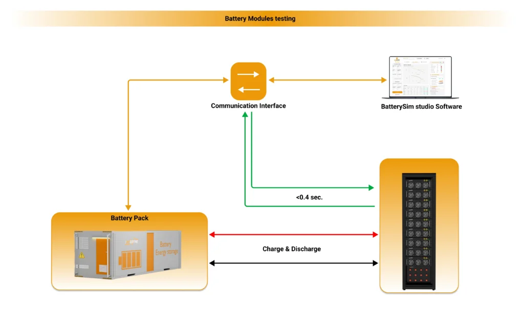
The most important evolution in battery cell testing is the shift from testing only physical cells to also emulating cells, modules, and complete packs in real time. A battery emulator is a programmable, bidirectional power system that electronically reproduces a battery’s terminal behavior — voltage as a function of SOC, internal resistance, dynamic polarization, power limits, and thermal coupling — sourcing real current on discharge and sinking real current on charge, with no physical cell present. When the emulator is driven by a high-fidelity real-time model and connected to actual power hardware through a regenerative converter, the methodology is called Power Hardware-in-the-Loop, or PHIL.

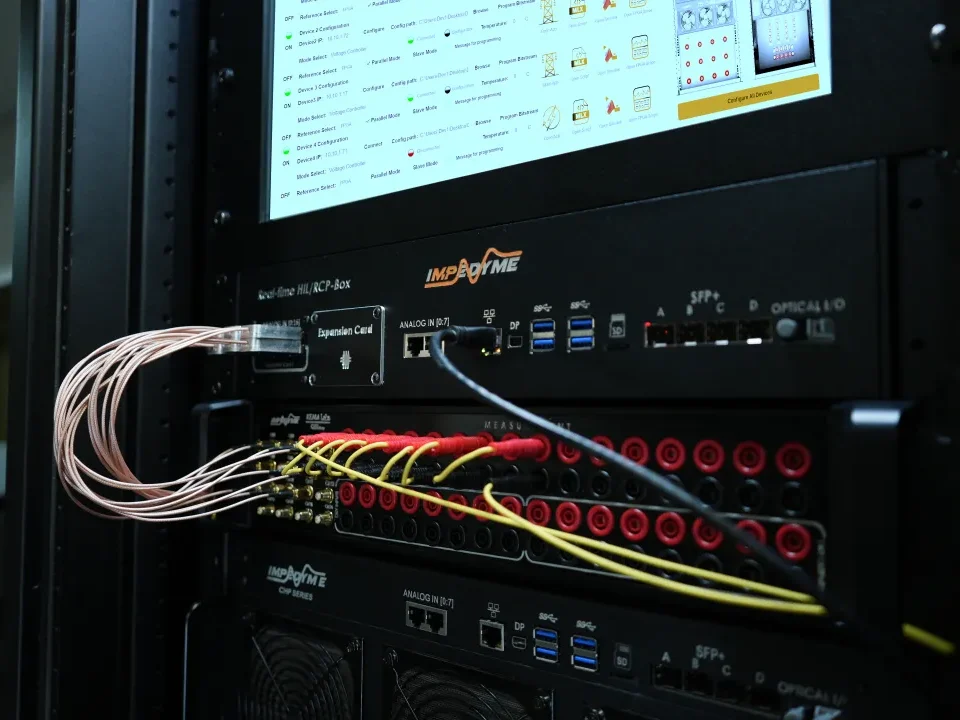
This is the core of Impedyme’s approach. Impedyme builds FPGA-based PHIL systems and Combined HIL-and-Power (CHP) platforms, and its BatterySim Studio software turns that hardware into a complete battery emulation and testing environment. The architecture is what makes it work: the battery model executes on Impedyme’s FPGA-based real-time hardware with model update rates fast enough to reproduce genuine electrical dynamics — not a slow approximation, but a physics-aware cell, module, or pack model running at nanosecond-class time steps and driving a fully regenerative power stage. The emulated battery connects directly to the real device under test: a BMS, a traction inverter, an on-board charger, a DC fast charger, or a DC-DC converter, all operating at production voltage and current.

Why Emulation Transforms the Battery Cell Testing Workflow

Safety without compromise. Overcharge, over-discharge, internal short circuits, ground faults, sensor failures, and thermal-runaway precursor scenarios can be scripted, executed, and replayed thousands of times — because there is no physical cell to vent, ignite, or destroy. The test team validates exactly how the BMS and power electronics respond to the most dangerous conditions a battery can produce, with zero cells at risk.

Speed and perfect repeatability. With a physical cell, reaching a specific test condition means hours of charging or discharging, followed by rest periods, with no guarantee the cell is in an identical state for the next run. With emulation, SOC, OCV, internal resistance, temperature behavior, and aging state change instantly and exactly. A regression suite covering hundreds of fault permutations runs overnight instead of consuming a quarter of physical lab time.

Edge cases physical cells cannot provide. How does the BMS respond to one aged cell among fresh ones? To a developing micro-short? To a cell whose impedance has doubled? To a pack with a deliberately induced SOC imbalance across modules? Staging these conditions with real cells is slow, expensive, sometimes dangerous, and never exactly reproducible. With BatterySim Studio, they are parameters in a test script.

Characterization and emulation in one loop. BatterySim Studio integrates EIS capability with automated equivalent-circuit-model fitting — Randles, Thevenin, multi-RC, and higher-order model structures with SOC-, SOH-, and temperature-dependent parameters. Data measured from real cells parameterizes the models; the models then drive the emulator; and the entire workflow lives in a MATLAB/Simulink-native environment, so the same model moves seamlessly between offline simulation, real-time HIL, and full-power PHIL.

The Impedyme Battery Cell Testing Ecosystem

Impedyme’s product family extends this methodology across the entire electrified powertrain and lab:

  • BatterySim Studio — real-time battery cell, module, and pack emulation with integrated EIS and ECM fitting, for BMS validation, charger testing, and powertrain integration.
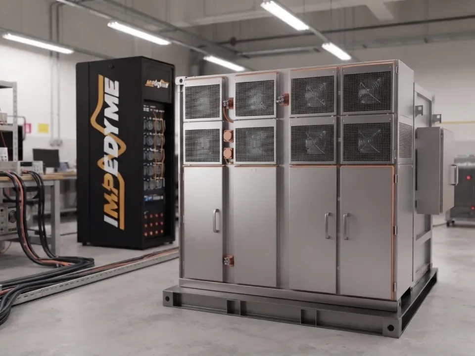
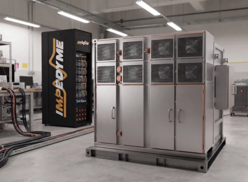
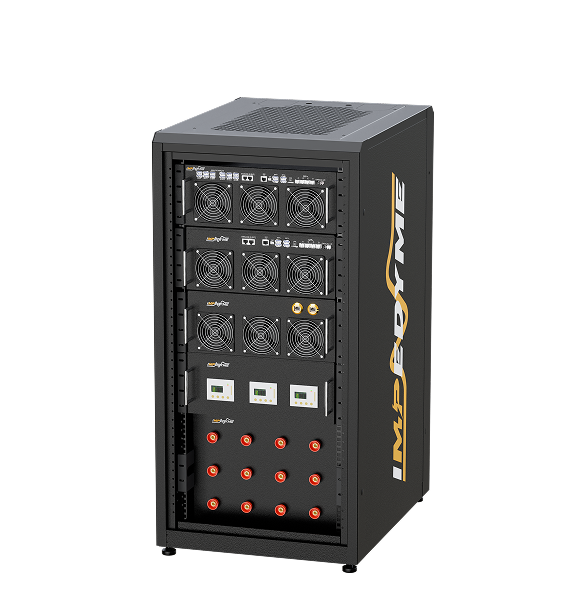
  • CHP Testbench — the FPGA-based real-time platform combining signal-level HIL and full-power PHIL in one regenerative system, available in CHP-150 half-cabinet and CHP 300 full-cabinet configurations and scalable through paralleling for higher power levels.
  • PowerHIL Studio — the orchestration and automation layer that configures hardware, scripts test campaigns, and coordinates multi-emulator setups from a single MATLAB-integrated environment.
  • GridSim Studio — grid emulation, so a battery system can be validated against realistic grid conditions, disturbances, and standards-driven grid-code scenarios.
  • MotorSim Studio — motor and drive emulation, allowing a battery or BMS to be tested against an emulated traction load with realistic regenerative braking dynamics.
  • 充电箱 — dedicated EV charging validation, exercising on-board chargers and DC fast-charging equipment against emulated 400 V and 800 V packs.
  • DroneSim Studio — propulsion emulation for UAV and eVTOL programs, where high-C-rate battery behavior and motor dynamics must be validated together without flying hardware.

Because every power stage in the family is regenerative and bidirectional, full-power testing recirculates energy rather than dissipating it — cutting operating cost, heat load, and facility requirements at the same time.

Emulation Complements Physical Testing — It Doesn’t Replace It

It is worth being precise: battery emulation does not eliminate physical battery cell testing. Physical characterization, abuse, environmental, and lifecycle testing remain essential, because only real cells can generate the ground-truth chemistry data and the certified safety evidence that standards demand. What emulation does is multiply the value of that physical data. Once a chemistry has been characterized and its model parameterized, that knowledge can be replayed across thousands of BMS and power-electronics test scenarios — safely, instantly, and identically every time. The physical lab focuses on what only physical cells can prove; the PHIL lab covers the combinatorial explosion of validation scenarios that physical cells never could. Together, they form a battery cell testing system that is faster, safer, and far more thorough than either alone.

Best Practices in Battery Cell Testing

Decades of collective industry experience distill into a handful of principles that separate strong test programs from weak ones:

  • Control temperature obsessively. Temperature confounds nearly every electrical measurement. Characterize at controlled, documented temperatures, and always record cell temperature alongside electrical data.
  • Combine time-domain and frequency-domain methods. HPPC and DCIR are fast and intuitive; EIS sees what they cannot. Programs that use both catch degradation earlier and parameterize better models.
  • Track internal resistance as an early-warning metric. 结论
  • Anchor everything to the 80% end-of-life definition. Consistent thresholds make data comparable across programs, suppliers, and time.
  • Use rest periods correctly. OCV measurements and reference tests require genuine relaxation; rushing them corrupts the SOC mapping that everything else depends on.
  • Couple cell characterization directly to BMS validation. The cell data should flow into BMS parameters and into the emulation models used to validate those parameters — one continuous pipeline, not two disconnected projects.
  • Automate ruthlessly. Long-duration campaigns succeed or fail on automation quality: scripted protocols, automatic data validation, and alarm-driven monitoring.

结论

Battery cell testing is where energy-storage products are truly made or broken. A rigorous program spans electrical characterization, performance testing, lifecycle and aging studies, environmental qualification, abuse and safety testing, and mechanical validation — and for vehicle battery cell testing, it must map cleanly onto a demanding stack of international standards from cell level to full pack. The equipment side of the equation has evolved just as far: a modern battery cell testing system is an integrated, automated, regenerative testbed in which battery emulation and Power Hardware-in-the-Loop now carry much of the validation load that physical cells once bore alone.

That is the gap Impedyme was built to close. With BatterySim Studio running physics-aware, real-time battery models on FPGA-based CHP hardware — supported by PowerHIL Studio orchestration, GridSim Studio and MotorSim Studio emulation, the Charger Box for EV charging validation, and CHP-150 and CHP 300 testbench configurations — engineering teams can characterize real cells, parameterize accurate models, and then validate BMS firmware and power electronics against emulated cells, modules, and full packs safely, repeatably, and at full power. The result is a battery cell testing workflow that is faster to run, safer to operate, and dramatically broader in coverage — exactly what the next generation of electric vehicles, drones, and energy-storage systems demands.

常见问题

What are the main types of battery cell tests?
Six families: electrical characterization, performance, lifecycle/aging, environmental, abuse and safety, and mechanical/vibration testing.

What is EIS, and why does it matter?
Electrochemical Impedance Spectroscopy applies a small sinusoidal excitation across a wide frequency range to separate ohmic, charge-transfer, and diffusion behavior. It catches aging signatures DC measurements miss.

What is the difference between cycle aging and calendar aging?
Cycle aging comes from active use (electrode stress, lithium plating). Calendar aging happens at rest, driven mainly by SEI growth — and accelerates at high storage SOC and temperature.

Can battery emulation replace physical cell testing?
No. Only real cells generate ground-truth chemistry data and certified safety evidence. Emulation multiplies that data’s value by replaying it across thousands of BMS and power-electronics scenarios safely and identically.

What specifications matter most when choosing a system?
Voltage/current range, measurement accuracy, sampling rate and bandwidth, channel count and independence, regenerative bidirectional power, and MATLAB/Simulink integration.