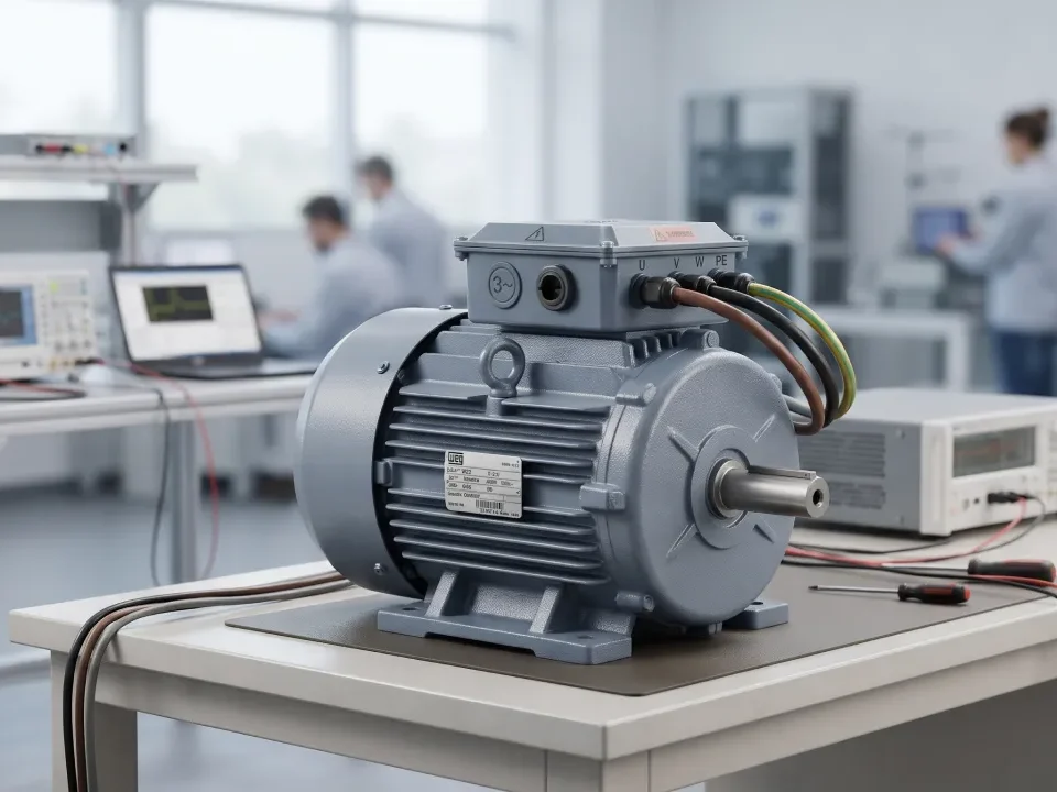
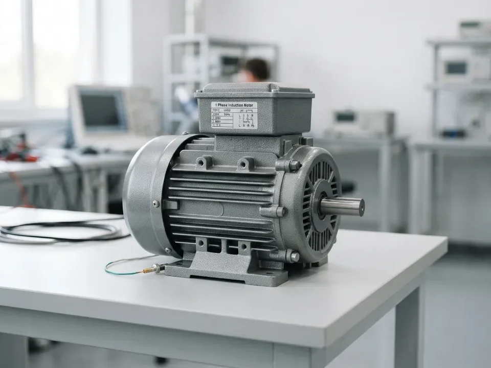
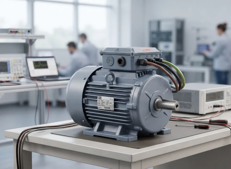
Synchronous Reluctance Motor card

应用知识电网电机产品知识网络研讨会

Synchronous Reluctance Motor header

Synchronous Reluctance Motor (SynRM)

目录

Synchronous reluctance motor (SynRM) is a three-phase AC machine that produces torque purely from the magnetic anisotropy of a steel rotor. It has no magnets, no cage and no rotor winding, and it turns at exactly the speed of the rotating stator field. Because the rotor carries no current, the synchronous reluctance machine eliminates the rotor copper loss that dominates induction-motor inefficiency. That is why the sync reluctance motor has become the standard magnet-free path to IE4 and IE5 efficiency in variable-speed drives, and why PM-assisted SynRM variants now appear in traction and compact drives. The trade-offs are just as specific: lower power factor, strongly nonlinear magnetics, no direct-on-line starting and heavy dependence on accurate rotor-angle information. This guide explains synchronous reluctance technology from first principles to bench validation. It covers how the AC reluctance motor produces reluctance torque, rotor design, control with and without sensors, and comparison with induction, PM and switched reluctance machines. It also covers how drive teams test synchronous reluctance drives, including the motor emulator route.

What is a synchronous reluctance motor?

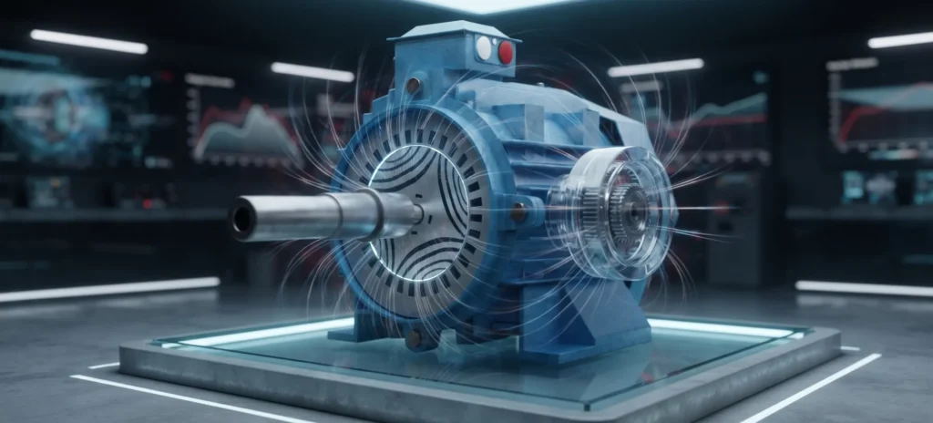
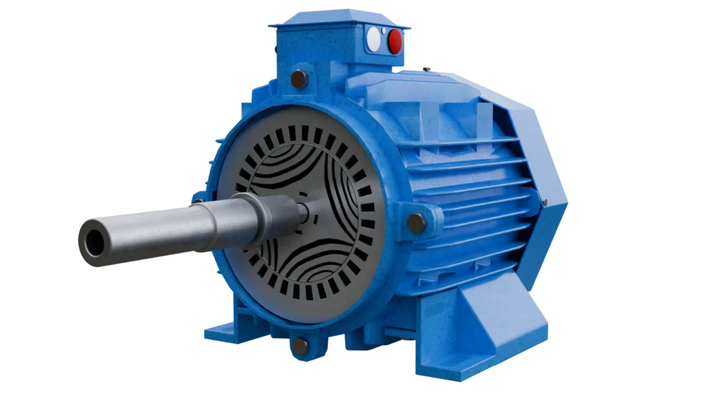
一个 synchronous reluctance motor is a rotating-field synchronous machine whose rotor has high magnetic permeance along one axis and low permeance along the perpendicular axis, so the rotor develops torque by aligning its “easy” axis with the stator field.

Anatomy:

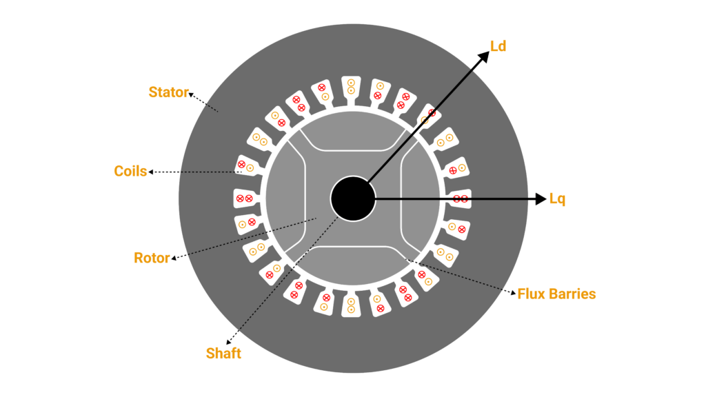
  • Stator: a conventional three-phase, distributed, sinusoidally wound stator—essentially an induction-motor stator.
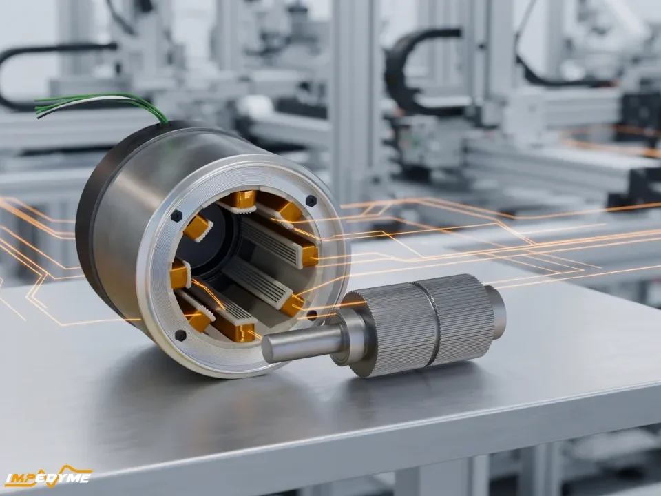
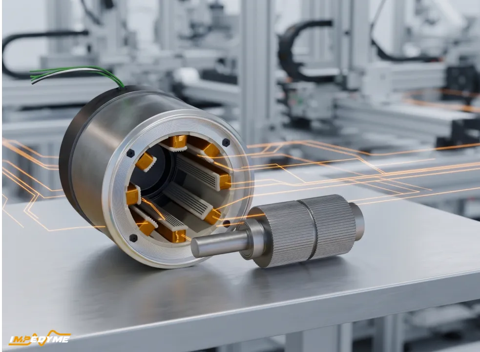
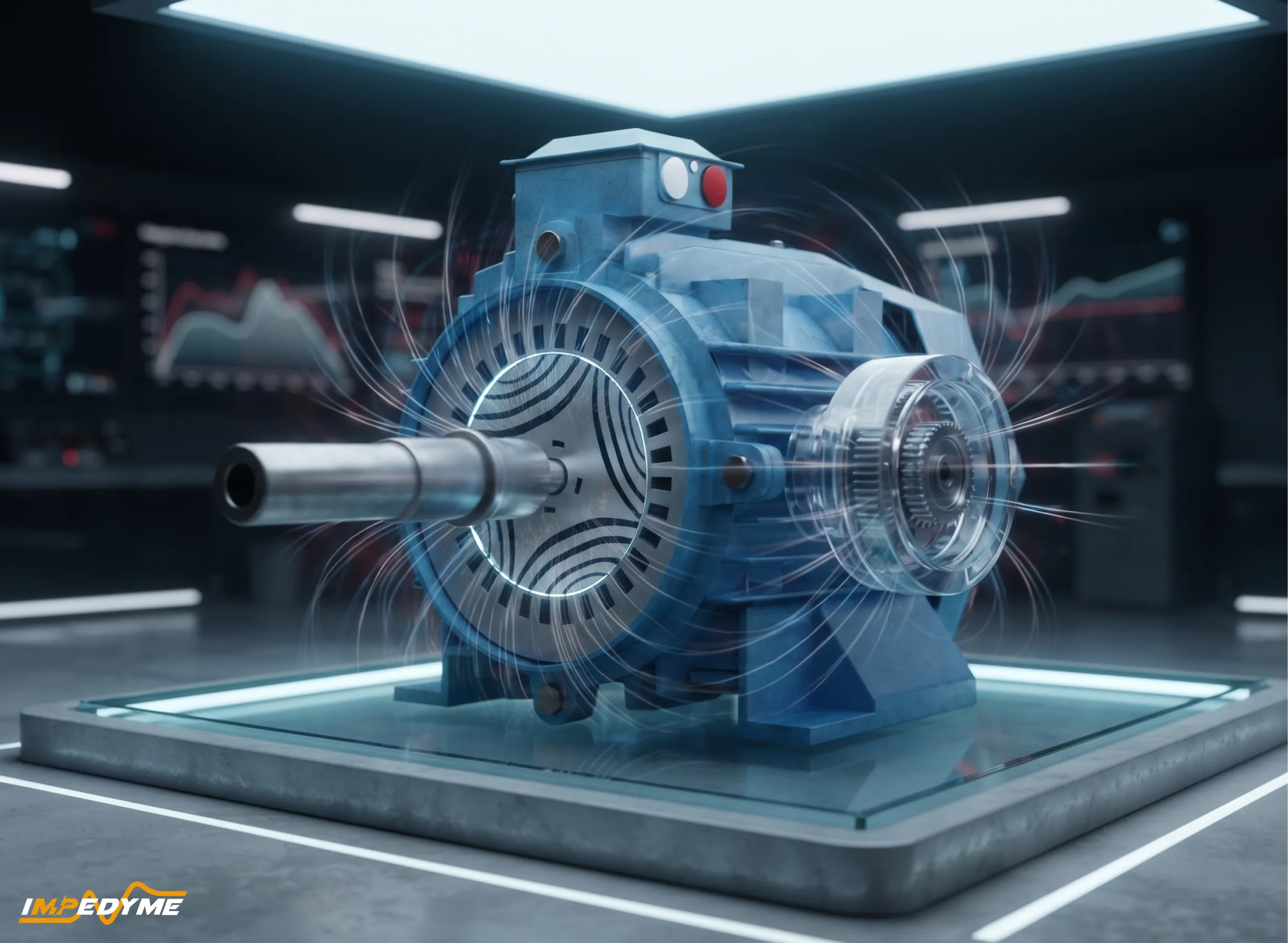
  • Rotor: thin electrical-steel laminations with punched air slots called flux barriers. Steel channels between barriers carry flux easily along the d-axis; barriers obstruct flux along the q-axis. Thin ribs at the periphery and radial posts hold the lamination together.
  • Absent: rotor winding, squirrel cage, permanent magnets, brushes.

Because the rotor turns at synchronous speed there is zero slip, so there is no fundamental rotor current and virtually no rotor copper loss; only small harmonic iron loss remains.

Naming: SynRM, SynRel, sync reluctance motor, synchronous reluctance machine, reluctance synchronous machine 与 AC reluctance motor describe the same machine. Switched and variable reluctance machines are relatives, not the same thing—they use concentrated coils, pulsed unipolar currents and doubly salient rotors.

Typical commercial envelope: industrial low-voltage SynRMs span roughly 0.75 kW to a few hundred kW (smaller series of about 0.75–55 kW in IEC frames 80–225, larger series toward about 315 kW), mostly 4-pole at 1,500 rpm rated speed, with maximum speeds of about 3,600–4,500 rpm and high-speed versions to about 8,000 rpm, in 380–690 V classes.

How does a synchronous reluctance motor work?

在 synchronous reluctance machine, the inverter-fed stator winding creates a magnetic field that rotates at a speed set by frequency and pole count. Flux prefers the low-reluctance path through iron. Because the rotor is anisotropic, any misalignment between its easy axis and the field distorts the field and stores extra energy, so the rotor is pulled toward the position of minimum reluctance. That pull is reluctance torque, the only torque-producing mechanism in a pure sync reluctance motor.

Picture a bar of anisotropic steel in a rotating field: it twists to line up its long axis with the field and follows at the same speed. Hold it back with a load and it lags by a load angle; the lag produces useful torque, up to a maximum.

Three consequences:

  1. Speed is fixed by frequency and pole count alone. A 4-pole SynRM at 50 Hz turns at 1,500 rpm at any load—no slip, no droop.
  2. Torque is commanded through the current vector—its amplitude and its angle relative to the rotor d-axis. The controller chooses the combination that minimizes current, loss or voltage.
  3. No load means no lag and no torque. As load rises, the load angle grows until pull-out torque. Beyond it the machine does not slip gradually like an induction motor—it loses synchronism, torque collapses and the drive trips. Overload capability is a hard limit.

Saliency ratio: what the d-axis and q-axis inductances really tell you

  • d-axis inductance (Ld): seen by current driving flux along the easy path through the steel channels—high.
  • q-axis inductance (Lq): seen by current driving flux across the barriers—low.

The difference between Ld and Lq sets torque per ampere. The ratio between them, called the saliency ratio, largely sets the power factor, torque density and constant-power speed range an AC reluctance motor can achieve. Staton, Miller and Wood (IEE Proceedings, 1993) described it as “by far the most important parameter” for power factor, torque per ampere and constant-power speed range.

Rotor typeTypical saliency ratioPower factor (magnet-free)
Simple salient-poleabout 3, rarely above 3.8roughly 0.5–0.6
2-barrier industrial TLAroughly 4–6roughly 0.6–0.7
Multi-barrier (3–5) industrial TLAroughly 6–9roughly 0.7–0.8
Axially laminated / traction and researchroughly 6–20 (unsaturated)up to about 0.8–0.85

bands combine published ranges with typical industrial values. A recent peer-reviewed design study notes that power factor above 0.8 requires saliency above about 9, explaining why magnet-free industrial machines sit between 0.6 and 0.8.

Saliency is not a constant. d-axis iron saturates as current rises, so Ld collapses—often by half or more between light load and overload—while Lq, dominated by air barriers and saturated ribs, changes much less.Saliency and power factor therefore fall with load. Cross-saturation couples the axes: q-axis current changes d-axis flux and vice versa, so the optimal current angle moves with load, and fixed-inductance controllers command the wrong angle at high torque.

How Ld and Lq are measured on hardware:

  • Standstill AC or step-voltage tests along each axis, integrating voltage minus resistive drop—quick, but little cross-saturation information.
  • Locked-rotor flux mapping over a grid of d/q currents, giving full self- and cross-saturation maps.
  • Loaded flux-linkage identification with a speed-controlled load machine, computing flux from steady-state voltages at speed.
  • Standstill self-commissioning without rotor locking, published by Hinkkanen, Pellegrino, Bojoi and co-authors (IEEE Transactions on Industry Applications), the basis of modern drive self-commissioning.

Present the result as a measured family of flux-linkage curves (Figure 4), not a single inductance value.

Why a synchronous reluctance motor cannot start direct-on-line

A pure SynRM has no cage, so it gets no induction torque, and no magnets. On a fixed 50/60 Hz supply, the field sweeps past far faster than the rotor can accelerate. The alignment torque reverses every slip cycle and averages out to zero, so the rotor vibrates and hums instead of turning. This is the defining starting limitation of every synchronous reluctance machine without a cage.

The requirement is a VFD with current-vector control and a known rotor position, so the field starts at zero frequency and stays locked to the rotor.The historical exception is the line-start SynRM with a partial cage; it is rare because the cage costs saliency and efficiency and synchronizes reliably only with modest inertia.

Commissioning consequence: initial rotor-position identification is mandatory before the first torque command. A pure sync reluctance motor has  180-electrical-degree ambiguity is harmless, but an error approaching 90 electrical degrees puts current on the wrong axis, producing a reversed start, a stalled start or a violent jerk.

synchronous reluctance machine

Types of synchronous reluctance motors

每一个 synchronous reluctance machine can be classified along four independent axes:

  • By rotor excitation: pure magnet-free SynRM; PM-assisted SynRM (ferrite or small rare-earth magnets in the barriers); line-start SynRM (partial cage).
  • By rotor construction: simple salient-pole; axially laminated anisotropic (ALA); transversally laminated anisotropic (TLA) multi-barrier—the industrial standard (see construction).
  • By winding and excitation: distributed sinusoidal synchronous machine (SynRM) versus concentrated-coil switched/variable reluctance machine.
  • By pole count and application: industrial IE4/IE5 (usually 4-pole); high-speed compressor (often 2-pole, mechanically limited); traction (4–8 poles, usually PM-assisted); servo (low inertia, ripple-limited).

Hysteresis motors and stepper motor or variable-reluctance motors also fall under the broad “reluctance motor” label, but neither is a SynRM. If you searched for an AC reluctance motor that runs continuously from a sinusoidal three-phase supply, the synchronous reluctance types above are the ones you want.

类型Construction & performancePros, cons & best use
Pure SynRMTLA rotor with no magnets; inverter start only; power factor ~0.6–0.8Pros: cheap, efficient, cool-running and magnet-free rotor. Cons: low power factor and torque ripple. Choose when: variable-speed pumps, fans and compressors need IE4/IE5 without magnets.
PM-assisted SynRMTLA rotor with ferrite or small NdFeB magnets; inverter start only; power factor ~0.8–0.9Pros: higher torque density, better power factor, easier field weakening. Cons: back-EMF, demagnetization risk and higher cost. Choose when: you need traction, high-speed or compact drives.
Line-start SynRMTLA rotor with cage bars; starts direct-on-line; power factor ~0.75–0.82Pros: needs no inverter, and IE4 is possible. Cons: pull-in is limited by load inertia. Choose when: you have fixed-speed, low-inertia loads without a drive.
Axially laminatedBent sheets in an axial stack; inverter start only; highest power factor of any magnet-free designPros: highest saliency. Cons: costly and weak at high speed. Choose when: you need research or specialist low-speed machines.
Salient-poleRotor with cut-out poles; starts from an inverter or a cage; power factor ~0.5–0.6Pros: very simple. Cons: low saliency and high ripple. Choose when: the machine is for teaching only.
Switched reluctance (related machine)Doubly salient rotor; needs a special converter; power factor not applicablePros: very robust. Cons: high torque ripple and noise. Choose when: you need harsh, high-temperature or high-speed drives.

PM-assisted synchronous reluctance motors (PMa-SynRM)

A PMa-SynRM places magnets in the rotor’s flux barriers, magnetized to oppose q-axis flux. These are usually low-cost ferrite, sometimes small amounts of rare-earth material. The magnets cancel flux that would otherwise leak along the hard axis and through the ribs. This raises effective saliency and adds modest magnet torque to the reluctance torque the synchronous reluctance machine already produces.

What it buys: higher torque density; power factor typically lifted into the 0.8–0.9 band (a 2023 Applied Sciences comparison from Xi’an University of Science and Technology reported 0.8 for an optimized ferrite-assisted SynRM versus 0.97 for an interior-PM motor; another ferrite-assisted design moved a magnet-free baseline from 0.48 to 0.915) ; and a wider constant-power speed range with easier field weakening.

What it costs:

  • Back-EMF at speed, even with the inverter off.
  • Demagnetization risk: ferrite coercivity falls at low temperature, so the worst case is a cold start with heavy flux-weakening or overload current; traction designs check ferrite at −40 °C.
  • Cogging and torque ripple (one published ferrite-assisted design reports 11.4%).
  • More complex control: polarity detection, temperature-dependent magnet flux, magnet-temperature-dependent MTPA tables.
  • New safety handling: after an inverter fault at speed, back-EMF can exceed the DC-link and drive uncontrolled generator mode through the diodes, requiring an active short-circuit strategy.

Where magnet-free still wins: a pure sync reluctance motor offers the lowest cost, full recyclability, no supply-chain exposure, no demagnetization mode and an intrinsically safe coast-down.

Line-start synchronous reluctance motors

A line-start SynRM combines a starting cage (aluminium cast into some barriers or the periphery) with a flux-barrier rotor.It accelerates asynchronously, then reluctance torque pulls it into synchronism, after which the cage carries almost no current.

  • Pro: grid-direct simplicity, no inverter; IE4 is achievable—a 5.5 kW prototype reported in Machines (2025, “Systematic Optimization Study of Line-Start Synchronous Reluctance Motor Rotor for IE4 Efficiency”) measured 92.2% at 1,200 rpm versus 90.7% at 1,175 rpm for the reference IE3 induction motor.
  • Con: the cage lowers saliency (power factor around 0.75–0.82), adds start losses and inrush, and pull-in is limited by load torque and inertia; every design has a “critical inertia” beyond which it cannot synchronize.

It persists in simple constant-speed, low-inertia applications and legacy retrofits.Once an inverter is present, the cage is pure penalty, so inverter-fed magnet-free designs have largely displaced it.

Construction of a synchronous reluctance motor: stator, rotor and flux barriers

The SynRM stator is a conventional distributed three-phase winding, so existing stator tooling, insulation systems, impregnation and rewind practices apply; many manufacturers share stator stacks with induction series. Essentially all synchronous reluctance machine distinctiveness lives in the rotor lamination.

Design levers: barrier count and shape (circular, segmented, “fluid”); rib and post widths (thin to saturate and limit q-axis leakage, thick enough for centrifugal stress); air-gap length; pole count (4 industrial, 2 very high speed, 6–8 traction); skew (often one slot pitch or stepped); and mechanical integrity at speed.

The magnet-free rotor runs markedly cooler than a cage rotor. Du, Zhang, Li and Hu’s same-volume comparison in Applied Sciences (2023) found the SynRM rotor core “about 40 °C lower than that of the IM,” and its stator core about 10 °C cooler. At equal winding temperature, Boglietti, Cavagnino, Pastorelli and Vagati at Politecnico di Torino (IEEE IAS 2005) measured 10% to 25% more torque from a SynRM than from the corresponding induction motor. A 2.2/4 kW comparison by the same group found about 10–15%. The flux barriers also remove rotor mass, so a sync reluctance motor has lower inertia, which helps dynamic loads accelerate. A cooler rotor also extends bearing grease life and reduces insulation stress.

Rotor geometries compared: salient-pole, axially laminated and transversally laminated

Simple salient-pole rotors remove iron between poles. They are cheap but have low saliency (rarely above about 3.8) and high ripple—mostly historical or for teaching.

Axially laminated anisotropic (ALA) rotors, introduced by Cruickshank, Menzies and Anderson (Proceedings of the IEE, 1966), stack bent U/V steel sheets with insulating spacers. They achieve the highest saliency (unsaturated 6–20) and lowest harmonic content, but are costly, awkward to manufacture, suffer eddy losses from slot harmonics, and are weak at high peripheral speed.

Transversally laminated anisotropic (TLA) rotors use punched multi-barrier laminations stacked like an induction rotor. Saliency is somewhat lower than ALA, but they are made on standard stamping lines, skewable and mechanically integral—the industrial standard.

Barrier counts and ripple: industrial TLA rotors use 2–5 barriers per pole. Ripple falls with rotor skew (often one stator slot pitch, or stepped) and barrier-end shaping—choosing or making asymmetric the barrier-end positions so slot harmonics cancel. Published asymmetric-end optimizations reach mid-teens percent ripple unskewed; with skew, single digits are achievable.

Speed limit: at high speed flux guides hang off thin ribs and posts, and stress concentrates at rib corners.

Rule of thumb: high volume, up to a few hundred kW, standard speeds → TLA with 3–4 barriers per pole; very high speed → TLA with fewer, wider posts, 2-pole, or dual-phase/sleeved rotors; low volume, maximum saliency, modest speed → ALA; teaching → salient-pole.

Flux barriers, ribs and saturation in a synchronous reluctance machine: the real design trade-off

More and wider barriers raise saliency and torque. The catch is that the thin ribs and posts holding the rotor together also carry flux. They saturate and leak q-axis flux, which caps the gain. Thicker ribs are mechanically safer but magnetically worse, so every AC reluctance motor rotor is a compromise between the two.

  • Barrier angle and end position: choosing where barriers meet the air gap relative to slot pitch—following design rules developed by Vagati and colleagues—lets slot harmonics cancel, tuning ripple in the lamination rather than in software.
  • Air gap: small gaps raise Ld (torque, power factor) but increase slot harmonics, iron loss and eccentricity sensitivity.
  • Steel grade: thin, high-grade non-oriented steel cuts iron loss and gives a sharp saturation knee that keeps ribs saturated at low flux.
  • Dual-phase or locally heat-treated laminations: ribs and posts are made non-magnetic (e.g., by nitriding) while flux guides stay magnetic, keeping mechanical continuity without a magnetic bridge.The cost is lower saturation flux density—published dual-phase work reports about 1.5 T, versus roughly 1.9–2.0 T for conventional non-oriented silicon steel. In a US Department of Energy non-rare-earth traction program, a dual-phase SynRM reached specific power comparable to dysprosium-free rare-earth designs. Non-magnetic titanium radial ribs are another published route.
sync reluctance motor

Synchronous reluctance motor vs induction, PM synchronous and switched reluctance 

属性SynRMInduction / PM synchronous / Switched reluctance
RotorSteel with flux barriersIM: steel with cage · PMSM: steel with magnets · SRM: doubly salient steel
磁体None (PM-assisted: ferrite or small NdFeB)IM: none · PMSM: yes, usually NdFeB · SRM: none
Rotor lossesVery lowIM: high (slip-driven rotor copper loss) · PMSM: low · SRM: moderate
SpeedSynchronousIM: 1–5% slip · PMSM: synchronous · SRM: synchronous with switching
Efficiency classIE4–IE5 with inverterIM: IE2–IE4 · PMSM: IE4–IE5+ · SRM: ~IE3–IE4
Power factor~0.6–0.8 (PM-assisted 0.8–0.9)IM: ~0.8–0.88 · PMSM: ~0.9–0.97 · SRM: n/a (pulsed)
转矩密度Moderate (≥ induction)IM: moderate · PMSM: highest · SRM: moderate-high
Torque ripple / noiseModerate / low-moderateIM: low / low · PMSM: low-moderate / low · SRM: high / high
Direct-on-line startNo (line-start variant only)IM: yes · PMSM: no (line-start variant only) · SRM: no
ConverterStandard 3-phase VSIIM: VSI or grid · PMSM: standard VSI · SRM: asymmetric half-bridge
Back-EMF when coasting无IM: decays quickly · PMSM: yes (a fault-case risk) · SRM: none
Control complexityHigh (saturation)IM: moderate · PMSM: moderate-high · SRM: high
Rotor temperature最低IM: highest · PMSM: low, but magnets are temperature-sensitive · SRM: moderate
Raw-material risk最低IM: low · PMSM: rare-earth exposure · SRM: lowest

Interpretation. The SynRM beats the induction motor on efficiency—no rotor current, cooler rotor, no slip; Lappeenranta University of Technology researchers measured a rated-point advantage of over 2 percentage points, larger at low speed and high load. It loses on power factor and therefore inverter current rating. It approaches PMSM efficiency, especially at part load where PM machines carry magnet-driven iron loss regardless of torque, but it needs more current for the same torque and has no magnet torque at low current. It is quieter and smoother than a switched reluctance machine, at the price of a sinusoidal three-phase inverter rather than a unipolar converter. 

Comparing motors alone misleads—compare motor plus inverter plus cable. Lower power factor means more kVA for the same kW.

Worked example (arithmetic only). A 75 kW pump at 400 V, motor efficiency 95%, needs about 78.9 kW electrical input.

  • At PF 0.85 (typical induction): 78.9 ÷ 0.85 ≈ 92.9 kVA, about 134 A.
  • At PF 0.70 (typical magnet-free SynRM): 78.9 ÷ 0.70 ≈ 112.8 kVA, about 163 A.
  • Uplift: about 20 kVA and 29 A—roughly 21% more inverter current for the same shaft power, often one inverter frame size up unless PM assistance or drive headroom is used.

How is a synchronous reluctance motor different from a switched reluctance motor?

PointSynchronous reluctanceSwitched reluctance
WindingDistributed, sinusoidal three-phaseConcentrated coils on salient poles
FieldSmooth rotating field, sinusoidal currentsPulsed unipolar phase excitation
ConverterStandard three-phase VSIAsymmetric half-bridge per phase
MotionContinuous synchronous rotationStepped pole-to-pole commutation
Ripple and noiseModerate; skew and barrier designHigh; dominant drawback
Genuine usesIE4/IE5 pumps, fans, compressors; PM-assisted tractionHarsh, high-temperature or high-speed robust drives

Variable reluctance and stepping motors belong to the switched family, stepping pole to pole for positioning rather than continuous power.

Advantages and limitations of synchronous reluctance motors

一个 synchronous reluctance motor trades a magnet-free, low-loss rotor for a more demanding drive. Each point below carries an engineering consequence.

优点

  • No magnets: lower cost, recyclability, no rare-earth exposure, no demagnetization.
  • No cage losses: rotor tens of kelvin cooler (about 40 °C in Du et al.’s 2023 Applied Sciences same-volume comparison) , extending bearing and insulation life or allowing higher rating per frame.
  • IE4/IE5 efficiency in standard IEC frames, often frame-compatible for retrofit.
  • Strong part-load efficiency: a 2019 Energies study from Istanbul Technical University measured a 2.2 kW SynRM at 85% at 25% load versus 72.7% for the induction reference (88.9% versus 86.3% at full load).
  • Low inertia for faster acceleration.
  • Good short-term overload, with torque per ampere independent of rotor temperature.
  • Simple, robust rotor.
  • No back-EMF when de-energized: a coasting sync reluctance motor cannot drive fault current or energize its terminals.

Limitations

  • Power factor 0.6–0.8 (magnet-free synchronous reluctance machine ), raising inverter kVA and cable current.
  • Higher ripple than a PMSM, requiring skew, barrier tuning or harmonic injection.
  • Nonlinear saturation and cross-coupling that break constant-parameter control.
  • No direct-on-line start.
  • Constrained constant-power range without PM assistance.
  • Thin-rib mechanical limits at high speed.
  • Sensitivity to rotor-position accuracy.

Choose a SynRM when: the load is variable-speed with many part-load hours; IE4/IE5 is required without magnets; rotor temperature or bearing life drives reliability; an inverter is already present; safe coast-down matters.

Avoid it (or go PM-assisted) when: the inverter cannot be upsized; constant-power range above roughly 3:1 is required; extreme torque density or very low ripple is required; high-inertia direct-on-line starting is needed; peripheral speed would force ribs too thick for useful saliency.

How are synchronous reluctance motors controlled?

Because a synchronous reluctance rotor has no magnet flux and strongly nonlinear magnetics, almost all of its performance is set by the control strategy.

  • Field-oriented current-vector control: phase currents are transformed into the rotor frame using the rotor angle, and fast loops regulate d- and q-axis current; torque is set by current magnitude and angle.
  • Maximum torque per ampere (MTPA): each torque has one current angle needing the least current. In a linear machine it would sit near 45 electrical degrees; in a real SynRM, saturation and cross-saturation push it upward with load, often beyond 55–60 degrees at overload.
  • Look-up-table/flux-map control: drives store d- and q-axis flux linkage as functions of both currents, from FEA or bench data, and pre-compute MTPA, voltage-limit and torque tables—the key step from textbook to production drive.
  • MTPV and field weakening: above base speed the controller moves along the voltage limit, reducing d-axis flux, and at top speed follows 
  • maximum torque per volt. A pure SynRM has little flux to trade, so its constant-power range is narrower than a PM machine’s.
  • Direct torque control / direct flux vector control: regulates stator flux and torque directly; less dependent on inductance values but still needs saturation-aware flux estimation.
  • Loss-minimizing and maximum-power-factor operation: at light load, reducing flux cuts iron loss; maximum-power-factor operation minimizes inverter kVA. Published work shows maximum-efficiency trajectories retain much of the saliency-limited power factor.
  • Torque-ripple mitigation: first in the lamination (barrier ends, skew), then by current harmonic injection cancelling dominant harmonics (typically 6th and 12th orders plus slot orders).
  • Rotor-angle accuracy: In an AC reluctance motor, an angle error misplaces the whole current vector. A 2025 sensitivity study in Mathematics found that staying within about ±3 electrical degrees of the MTPA trajectory limits torque or loss penalty to about 1%, with saturation narrowing the allowable band by up to 25%; the penalty grows rapidly beyond, on the order of several percent at 10 electrical degrees.
  • Current-loop bandwidth and switching frequency: low Lq means fast q-axis current and larger switching ripple. Industrial drives switch at about 4–16 kHz with current-loop bandwidth roughly a tenth of the sampling rate; gains should be scheduled because incremental inductance may halve between light load and overload .

Commissioning sequence:

  1. Parameter identification: stator resistance, inverter dead-time/voltage-error compensation.
  2. Initial angle detection before any torque command.
  3. Flux-map calibration: standstill self-commissioning or loaded mapping.
  4. MTPA table validation against a torque transducer at several loads.
  5. Speed-loop tuning with actual load inertia.
  6. Field-weakening and current-limit checks at maximum speed and minimum DC-link voltage.

Sensorless control and low-speed position estimation

The inherent saliency of a synchronous reluctance machine gives a strong position signature: the inductance seen by the inverter varies with rotor angle, even at standstill.

Implementation:

  • Medium/high speed: back-EMF or flux observers (including “active flux” methods).
  • Low speed/standstill: high-frequency or pulse injection, tracking angle from the current response to a small test voltage.
  • Polarity and initial angle: irrelevant ambiguity for pure SynRM; PMa-SynRM polarity must be resolved, typically by a saturation test.
  • Blended hand-over: estimates are weighted across a speed band for smooth transition.

Pitfalls:

  • Cross-saturation biases the estimated angle under load; Guglielmi, Pastorelli and Vagati showed injection estimates converge to a load-dependent wrong angle unless compensated with flux maps.
  • Saturation shrinks the saliency injection relies on; at heavy overload the signal can weaken or vanish.
  • Audible injection noise, reduced by random or variable-angle injection and higher injection frequency.
  • Estimate loss under fast torque transients or near zero current.

Encoder or resolver remains mandatory for lifting and hoisting (full torque at zero speed), precise positioning, high-dynamic traction, and functional-safety functions relying on verified speed or position.

Efficiency classes, standards and energy savings (IE4 and IE5)

The synchronous reluctance motor is the common magnet-free route to IE4 and IE5. It removes the rotor loss that limits induction motors without the cost and supply exposure of magnets.

Standards:

  • IEC 60034-30-1: IE classes for line-operated motors; the 2025 edition adds IE5 limits.
  • IEC TS 60034-30-2: IE classes for variable-speed motors not designed for direct-on-line operation, including SynRMs; its limits account for added harmonic losses on converter supply (15% more losses up to 90 kW, 25% above).
  • IEC 60034-2-1 / IEC 60034-2-3: loss determination for line-operated and converter-fed machines.
  • IEC 61800-9-2: efficiency classes for the power drive system (IES0–IES2) and converter, with standardized part-load points.
  • Regulation (EU) 2019/1781 requires losses at specified load points in the EU.

Rate the package, not the motor. A sync reluctance motor cannot run without its inverter, so efficiency is meaningful only as a power drive system figure or a motor figure on a defined converter supply. Every quoted efficiency must state test method, supply (switching frequency) and whether inverter losses are included. The converter may also show slightly higher loss driving a SynRM because of the higher current.

Realistic savings:

  • Full load: about 1–3 percentage points over an equivalent IE3 induction motor on inverter supply.
  • Part load: the gap widens; published pump-system studies report SynRM configurations outperforming induction by up to 7 percentage points at low loads, and a chiller-system study reported 2.53–4.63% energy savings across load profiles.
  • Payback: 2 points on a 75 kW pump running 6,000 h/year saves about 75 × 0.02 × 6,000 ≈ 9,000 kWh/year—often enough to recover an IE5 SynRM premium over IE3 within one to three years. More part-load hours mean faster payback.
  • Caveat: hydraulic and aerodynamic losses dominate system efficiency, so a several-point motor gain may become about one point at system level, as published pump case studies show. Model the whole system.

Applications of synchronous reluctance motors across industries

Each entry gives the reason a synchronous reluctance machine fits, the variant used, the main caveat and the test it implies.

  • Pumps, fans, compressors and HVAC: part-load duty and continuous running suit pure 4-pole IE4/IE5 SynRMs, often retrofitted into existing frames; caveat—inverter sizing for power factor. Test: part-load efficiency at IEC 61800-9-2 points and long-duration thermal behaviour.
  • Water and wastewater: 24/7 variable-flow duty where energy dominates life-cycle cost; cool rotor helps bearings; usually sensorless. Caveat—long cables amplify kVA and reflected-wave effects. Test: sensorless start under head and restart after power loss.
  • Automotive traction and e-axles: usually PM-assisted for magnet-cost and thermal reasons; a DOE program targeting 55 kW peak and 30 kW continuous over 2,800–14,000 rpm found conventional SynRMs lagged in power density and constant-power range. Test: drive-cycle efficiency maps, deep field weakening, active short-circuit and uncontrolled generation.
  • Commercial and off-highway vehicles: robust high torque at moderate speed; pure or PM-assisted with encoders; severe overload and thermal cycling. Test: repeated overload cycles and pull-out margin at minimum DC-link voltage.
  • Aerospace and more-electric aircraft (fuel pumps, ECS fans, actuation): no magnet back-EMF in winding faults and high rotor-temperature tolerance; a 2025 NASA study quantified SynRM versus PM drivetrain trade-offs for electric aircraft, and SynRMs have been patented for flap actuation at about 5 kW and below. Caveat—power-to-weight penalty. Test: fault-tolerant operation, phase loss, high-ambient endurance.
  • Machine-tool spindles: cool rotor limits thermal growth; low inertia; high-speed TLA with reinforced ribs. Test: overspeed proof and field-weakening behaviour.
  • Robotics and servo axes: low inertia and overload, but torque ripple is the limiter. Test: low-speed smoothness and encoder-based accuracy.
  • Renewables and generator mode: robust magnet-free generators and regenerative braking; pure SynRM generators need inverter-supplied magnetization, so PM assistance is common. Test: four-quadrant operation and DC-link behaviour in regeneration.
  • Refrigeration compressors: hermetic variable-speed duty, often ferrite-assisted. Test: loaded sensorless starts against pressure and low-temperature demagnetization.
  • Teaching and research benches: clean demonstration of reluctance torque, saturation and sensorless control; constant-inductance textbook models mislead. Test: flux-map identification and controller comparison on a common platform.

Designing and simulating a SynRM: the FEA workflow

Designing a synchronous reluctance rotor is an iterative loop:

  1. Specification: rated/peak torque, base and maximum speed, DC-link range, thermal class, efficiency, power factor and NVH targets.
  2. Pole and slot selection, so barrier ends interact favourably with slot pitch.
  3. Initial barrier layout: count, shape family, barrier-to-iron insulation ratio.
  4. Parametric/optimization sweep of barrier widths, angles, ribs and air gap, trading torque, ripple and power factor.
  5. 2D magnetostatic FEA for flux maps over the d/q current plane, saliency and MTPA locus.
  6. Transient FEA for ripple, harmonic iron loss and current harmonics with realistic inverter waveforms.
  7. Iron-loss and demagnetization checks for PM-assisted variants, including cold worst cases.
  8. Mechanical stress check of ribs and posts at maximum and overspeed.
  9. Thermal and NVH checks, including radial force harmonics.

What matters downstream: the saturation and cross-saturation flux maps. The same data feeds the controller’s MTPA and field-weakening tables, sensorless compensation, and the real-time model on the test bench. Treat the flux map as a versioned, validated deliverable shared by the design, controls and validation teams on every AC reluctance motor project.

Testing and validating a synchronous reluctance motor and its drive

测试What it provesInstrumentation demands
Standstill identification and flux mappingMagnetic modelPhase-aligned V/I measurement; inverter voltage-error compensation; locked/free rotor fixture
No-load and loaded efficiency mappingIE class, part loadPower analyzer with low-PF accuracy and PWM bandwidth; torque transducer class ~0.05–0.1% FS; speed encoder
Pull-out and overloadHard torque limitTorque transducer headroom; fast current capture
Ripple and NVHRipple, vibration, noiseHigh-bandwidth torque sensing, accelerometers, microphones; stiff coupling
Thermal enduranceWinding and rotor temperatureRTDs/thermocouples; rotor telemetry or infrared
Sensorless at zero/low speedLoaded start, angle accuracyEncoder or resolver as reference
Field weakening and voltage limitConstant-power range, MTPVDC-link control; high-speed dynamometer
Fault casesTrip, phase loss, overspeed; PMa uncontrolled generationDC-link overvoltage capture; protection timing

Why low power factor makes SynRM efficiency easy to get wrong. Active power depends on the cosine of the voltage-current phase angle; when that angle is large, a small phase or timing error changes measured power far more than at unity power factor. The European EMPIR MICEV metrology project (Metrology for Inductive Charging of Electric Vehicles) showed that a 2-degree phase error at 100 kHz, with a 45-degree phase shift between voltage and current, already gives a 3.5% active-power error—a wireless-charging measurement rather than a motor test, but the same trigonometry applies to motor benches. At light-load power factor near 0.2, even 0.1 degree produces close to 1% input-power error—enough to move a motor across an IE class boundary. Rules: use an analyzer specified for low-power-factor accuracy and PWM bandwidth; use current sensors with known phase response and apply phase/deskew correction; keep probes phase-aligned to a small fraction of a degree; measure input and output on one synchronized instrument. 

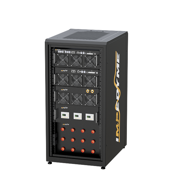
Two bench options: 一个 测功机 couples the real motor to a load machine; a real-time motor emulator, implemented by power hardware in the loop (PHIL) motor emulator equipment, replaces the motor with a controlled converter that behaves like the machine at the inverter test terminals.

Motor emulator vs dynamometer for SynRM drive testing

Dynamometer: needs the physical machine, coupling, load machine and test cell; measures real losses, torque and thermal behaviour; does not exist before the prototype; slow to reconfigure; mechanically bandwidth-limited; risky for fault and overspeed work.

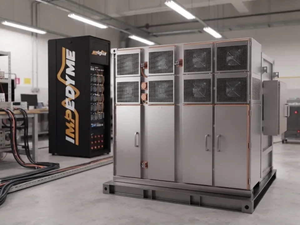
Power-HIL motor emulator: a controlled converter drives the device-under-test inverter’s terminals according to a real-time synchronous reluctance model, so inverter hardware and firmware are exercised before any rotor is cut, many motor variants are tested in a day by swapping flux maps, destructive fault and overspeed cases run safely and repeatably, and every internal state—flux, torque, rotor angle, estimator error—is observable.

What the emulator route demands:

  • Model fidelity with saturation and cross-coupling (flux-map based), ideally with spatial harmonics.
  • Accurate position and flux feedback timing, with emulated encoder/resolver signals consistent with the model angle.
  • Converter bandwidth and dv/dt capability at the emulated terminals. Published research emulators show the scale: a Karlsruhe Institute of Technology multilevel PHIL converter reached PWM frequencies up to 120 kHz at more than 100 kW, and a 17-level hybrid-converter bench reported an effective 1 MHz switching frequency.
  • Low model-loop latency: published FPGA machine models use 667 ns time steps (1.5 MHz) or faster, industrial emulators update models at up to 3.125 MHz, and FEA-based signal-level HIL reports about 1.3 µs total latency.Impedyme CHP Series figures for emulator bandwidth, dv/dt and latency:

Use the emulator to de-risk firmware,  HIL 保护 and sensorless algorithms early and to cover fault cases safely; use the dynamometer to certify efficiency, thermal performance and NVH on the final machine.

Modeling saliency, saturation and cross-coupling in real time

Why constant-inductance models mislead for an AC reluctance motor : saliency collapses with saturation, overstating torque per ampere at high load; cross-saturation shifts the torque angle, so MTPA tables and estimators tuned on such models fail on hardware; and slot and barrier harmonics create ripple and current distortion that a sinusoidal model hides.

Modeling choices:

  • Flux-map look-up tables from FEA or measurement—published KIT work stored measured flux linkages and differential inductances on a 2 A grid with 16-bit precision, solving the model on an FPGA every 667 ns.
  • Spatial harmonics via rotor-angle-dependent (current-current-angle) tables.
  • Iron-loss representation through loss elements or maps, so emulated efficiency and current phase are realistic.
  • Time step and latency fast enough that the emulated machine looks correctly inductive between PWM edges—sub-microsecond steps for current loops in the tens of kHz.

Validation: compare emulated and measured phase currents, torque estimate 与 MTPA locus at identical speed, DC-link voltage and current command. Published emulator work reports fixed-point versus floating-point model differences below 0.01% and describes current steps and ripple as “precisely reproduced” against a real machine, but rarely quotes numeric emulated-versus-measured error. Impedyme’s achieved model-versus-measurement agreement for SynRM: 

Common problems with synchronous reluctance motors and how to fix them

Most field problems with a synchronous reluctance motor trace back to three roots:  wrong or missing rotor-angle information, a magnetic model that ignores saturation, and an inverter sized as if the motor had an induction motor’s power factor.

SymptomLikely causeFix
Vibration, no rotation at startMissing initial position estimate; direct-on-line attemptEnable initial-angle detection; use drive SynRM mode; never connect a pure SynRM to the grid
Loss of synchronism under shock loadPull-out exceeded; low current limit; wrong MTPA tableVerify overload margin; raise limit within rating; re-identify flux maps
Lower torque than expectedAngle offset; saturation unmodeled; inverter current limit from low PFCalibrate encoder offset; use flux-map control; check kVA sizing
Audible whineInjection sensorless; low switching frequencyHigher or random injection; raise switching frequency; earlier observer hand-over
Ripple and resonanceBarrier/slot harmonics; no skewHarmonic current injection; skewed rotor; check coupling resonance
Hot stator, cool rotorHigher stator current for same torqueConfirm MTPA; consider PM assistance or larger frame; improve cooling
Overcurrent entering field weakeningWrong voltage-limit model; regulator saturationFlux-map field-weakening tables; voltage margin; anti-windup
(PMa) Torque loss after cold operationFerrite demagnetization at low temperatureLimit demagnetizing current when cold; recheck magnet operating point
(PMa) DC-link overvoltage after trip at speedUncontrolled generation through diodesActive short-circuit; size DC-link/braking for worst-case back-EMF

conclusion

The synchronous reluctance motor delivers what induction motors cannot—near-zero rotor loss, a cool rotor and IE4/IE5 efficiency—without the magnets, cost and supply-chain exposure of PM machines, but it hands the complexity to the drive. Whether you call it a SynRM, a sync reluctance motor, a synchronous reluctance machine or an AC reluctance motor, its performance depends on saturation-aware flux maps, accurate rotor-angle information, inverter sizing that respects power factor and a phase-accurate efficiency bench. The fastest way to get those right is to validate inverter, firmware and sensorless algorithms against a high-fidelity synchronous reluctance model before the first rotor is cut, then confirm on a dynamometer. Impedyme’s FPGA-based real-time motor emulation and power hardware in the loop platforms—the CHP 系列 hardware with MotorSim Studio 与 PowerHIL Studio—let motor-drive, EV and validation teams run flux-map-based SynRM and PM-assisted SynRM models at the inverter terminals, reproduce fault and overspeed cases safely, and compare emulated and measured behaviour point by point, so synchronous reluctance drives reach the test cell already proven.

常见问题 

Does a synchronous reluctance motor have magnets?

 No—a pure synchronous reluctance motor has no magnets, no cage and no rotor winding; torque comes only from the steel rotor’s saliency. Only the PM-assisted variant adds ferrite or small rare-earth magnets in the flux barriers, typically lifting power factor from the 0.6–0.7 band toward 0.8 or higher.

Can a SynRM run without a VFD? 

Not in its pure form. With no cage there is no starting torque, so a SynRM connected directly to a 50 or 60 Hz supply vibrates instead of accelerating. It needs an inverter with current-vector control and a known rotor angle; only line-start variants with a partial cage can start direct-on-line, and only with low-inertia loads.

Is a synchronous reluctance motor more efficient than an induction motor? 

Usually yes, because its rotor carries no current and has almost no rotor copper loss. Published comparisons show around 2 percentage points at rated load and much more at part load—a 2019 Energies study measured 85% versus 72.7% at 25% load for 2.2 kW motors. Always compare motor-plus-drive figures under the same test method.

What power factor does a SynRM have? 

A magnet-free SynRM typically runs at a power factor of about 0.6 to 0.8, set mainly by its saliency ratio; published design work indicates saliency above roughly 9 is needed to exceed 0.8. PM-assisted designs reach about 0.8–0.9, cutting the inverter current rating needed for the same shaft power.

Is a synchronous reluctance motor suitable for electric vehicles? 

Yes, but usually in PM-assisted form. Pure SynRMs struggle with power density and constant-power range: against a traction target of 55 kW peak and 30 kW continuous over 2,800–14,000 rpm, conventional magnet-free designs lagged rare-earth machines. Ferrite assistance, dual-phase steel or stronger rotor structures close much of that gap.

How is a SynRM controlled without a position sensor? 

Sensorless SynRM drives blend high-frequency injection, which tracks rotor saliency at standstill and low speed, with flux or back-EMF observers at higher speed. Cross-saturation must be compensated using flux maps because it biases the angle under load; holding error within about ±3 electrical degrees keeps the MTPA penalty near 1%.

How is a synchronous reluctance motor tested? Testing runs from standstill flux-map identification through efficiency mapping, pull-out, ripple, thermal and fault tests. Low power factor magnifies phase errors—EMPIR MICEV metrology showed a 2° error at a 45° phase angle causes about 3.5% power error—so instruments must be phase-aligned. A power-HIL motor emulator validates the inverter before any rotor exists.