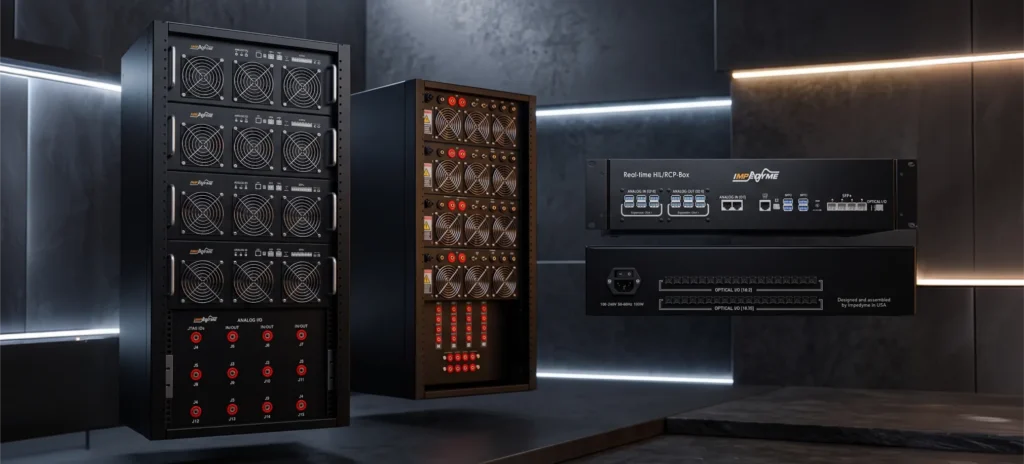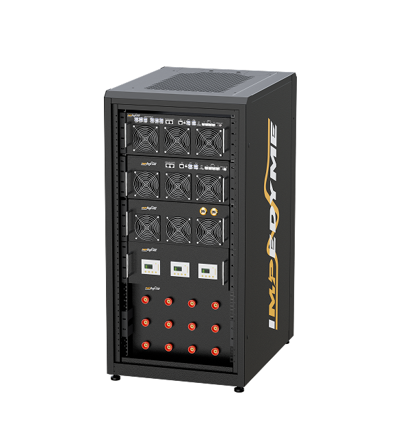

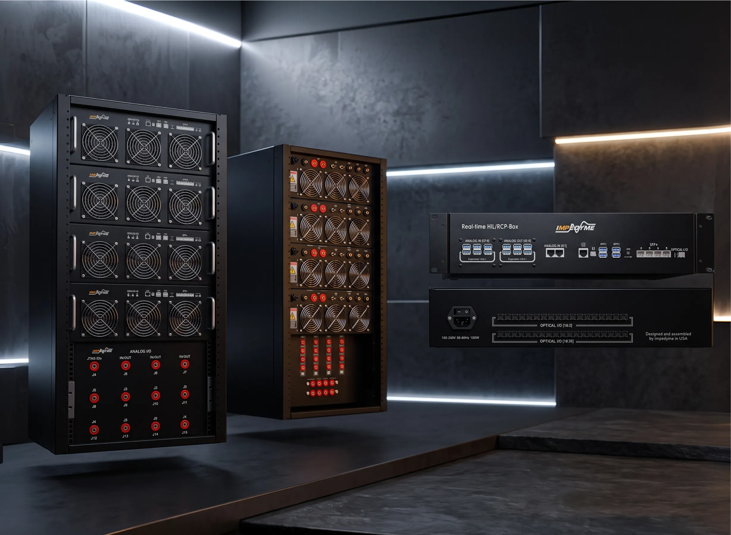
Hardware in the loop testing for EV powertrain development has become the single most effective way to validate battery management systems, traction inverters, and onboard chargers before a physical prototype ever turns a wheel. At Impedyme, our FPGA-based CHP Series platforms and software suite let engineering teams reproduce cell-level battery behavior, nanosecond-scale inverter switching, and complete charging interactions in a safe, repeatable, closed-loop environment. This guide explains why HIL for EV powertrain outperforms physical prototyping, how it applies to each subsystem, and how the Impedyme ecosystem addresses every stage of the validation journey — from a battery management system on the bench to a full electric drive under simulated road load.
If you are a power electronics engineer, a BMS or inverter developer, an R&D validation lead, or a test-lab manager, this article is written for you. It goes deeper than a marketing overview: it covers the physics of switching fidelity, cell-level electrochemical emulation, fault-insertion strategy, functional-safety context, and the automation pipelines that make modern electric-vehicle programs ship on time.
The electric drivetrain is now a software-defined system, and the software is only as trustworthy as the tests behind it. Several converging industry trends are precisely why hardware in the loop testing for EV powertrain has moved from “nice to have” to “non-negotiable.”
Doubling the DC-link voltage from 400V to 800V halves the current for the same power. Because resistive losses scale with the square of current, an 800V architecture can cut those conduction losses by roughly three-quarters, reduce cable mass, and unlock ultra-fast charging. In practice, an 800V pack can charge from 10% to 80% in under 20 minutes, while many 400V systems plateau around 150–200 kW of charging power without significant thermal strain. But 800V stresses insulation, changes fault energies, and forces every component — inverter, motor, onboard charger, and BMS — to be re-validated at higher electrical potential.
Silicon carbide (SiC) MOSFETs switch far faster than silicon IGBTs, enabling smaller, lighter, cooler-running inverters. That speed is a double-edged sword for test engineering: switching transients now occur in tens of nanoseconds, so any test system that cannot resolve them will misrepresent losses, ripple, and protection behavior.
Chargers must interoperate across CCS, CHAdeMO, GB/T, and the evolving NACS/ISO 15118 landscape, including secure Plug and Charge communication. A charger that works with one vehicle and fails with another is a warranty and reputation problem waiting to happen.
Bidirectional onboard chargers turn parked EVs into grid assets. Vehicle-to-grid (V2G) and vehicle-to-home (V2H) capability introduce entirely new fault, stability, and standards-conformance scenarios that must be validated before any hardware touches a live grid connection.
Solid-state and sodium-ion cells are moving from lab to roadmap. They bring higher balancing currents, different thermal signatures, and new degradation behavior that a BMS must handle correctly on day one.
Each of these trends multiplies the number of required test cases while raising the cost of a missed fault. Physical prototyping alone simply cannot keep pace — which is exactly the gap HIL fills.
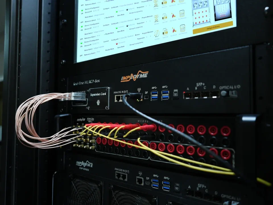
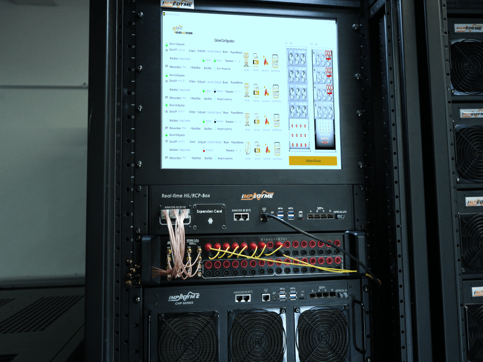
Hardware in the loop (HIL) testing connects a real controller — a BMS, an inverter controller, or an onboard-charger controller — to a real-time simulation of the electrical system it manages. The controller behaves as though it is wired to a real battery pack, motor, or grid; in reality it is exchanging signals with an Impedyme real-time target running high-fidelity digital twins. Every input the controller expects — cell voltages, phase currents, encoder pulses, CAN messages, temperature readings — is generated by the simulator, and every output the controller produces is fed back into the model, closing the loop.
The advantages over physical prototyping are decisive:
| Dimension | Physical Prototype Testing | HIL for EV Powertrain |
|---|---|---|
| Safety | High-voltage, thermal-runaway, and overcurrent hazards to staff and equipment | Faults simulated safely; no danger to people or hardware |
| Reproducibility | Difficult — real batteries drift, ambient conditions vary | Perfectly repeatable, fully scripted scenarios |
| Test duration | Multi-hour charge/discharge cycles | Accelerated and run in parallel |
| Cost | Multiple expensive prototypes and dynamometers | One reusable bench emulates many configurations |
| Fault coverage | Dangerous faults (short-circuit, overtemperature) often untestable | Overcurrent, short-circuit, and sensor loss all tested safely |
| Availability | Waits for the full system build | Test the controller as soon as firmware exists |
Impedyme structures this as a staged workflow that moves from signal to power:
This staged approach means teams catch the cheapest-to-fix defects first and only commit expensive power hardware once the control logic is proven.
The fidelity ceiling of any HIL system is set by how fast it can update. Conventional processor-based platforms are typically limited to update rates around 50 kHz, because a communication bus physically separates the processor from the input/output, and that latency consumes much of each simulation period. That is perfectly adequate for grid-scale electrical models, but far too coarse for a modern traction inverter switching at tens of kilohertz with nanosecond-scale edges.
| Attribute | CPU-Based HIL | Impedyme FPGA-Based HIL (CHP Series) |
|---|---|---|
| Typical update rate | ~50 kHz | Simulation steps as fast as 1 microsecond |
| PWM edge capture | Coarse; ripple is missed | ~5 ns edge capture at a 200 MHz FPGA clock |
| Machine-model update | Multi-microsecond | On the order of 90 nanoseconds |
| Switching fidelity | Average-value only | True high-frequency switching for Si, SiC, and GaN |
| Failure mode | False overcurrent trips, missed harmonics | Accurate ripple and EMC insight |
A useful engineering rule of thumb is that the simulation time step should be at least ten times smaller than the period of the fastest signal you need to resolve. The impact is quantifiable. National Instruments, in its guidance on HIL testing for power electronics systems, notes that “for a simulation loop with a 25 µs period, the simulated response to an 8 kHz PWM has as much as 20% relative error… the same simulation running at 1 µs has only 0.75% error in the PWM measurement.” Peer-reviewed work reaches the same conclusion: as Wang et al. state in Electric Power Systems Research, “as compared to power systems, in which a 50 μs time-step is sufficient for simulating electrical grid elements, an accurate power electronic system simulation with a PWM control strategy should be under 1 μs.”
This is the core reason Impedyme builds its platforms around FPGA-based real-time emulation: by integrating processing and I/O on the same chip, the CHP Series eliminates the bus-latency bottleneck and reaches simulation steps down to a microsecond, with PWM edges captured at nanosecond resolution.
The battery management system is the critical safety and intelligence layer of an electric vehicle battery pack, responsible for state of charge estimation, state of health calculation, cell balancing, thermal regulation, and isolation monitoring. To validate BMS hardware and firmware under closed-loop conditions, an HIL system must emulate the complex physical behaviors of hundreds of lithium-ion cells in series and parallel.
Impedyme’s BMS testing solution supports up to two hundred and fifty-six individual cell emulation channels with physical galvanic isolation rated up to one kilovolt. Each emulator channel operates as a highly precise, bidirectional voltage source capable of sourcing balancing current during passive charging phases and sinking current during cell-balancing operations. To monitor thermal feedback algorithms, the system incorporates high-resolution thermistor emulation. This emulation reproduces resistive temperature sensors (using standard ten-kilohm Negative Temperature Coefficient curves) with high accuracy and fine resolution, allowing engineers to validate how the BMS responds to thermal fluctuations and cell-overtemperature conditions.
To simplify testbench wiring and lower overall costs, Impedyme incorporates Cell Monitoring Device Emulation, or CMDE. In a real battery pack, local cell-monitoring chips measure cell voltages and temperatures, digitize the data, and transmit it to the central Battery Control Unit over an isolated SPI daisy-chain communication link. With CMDE technology, the HIL simulator directly emulates the register command interfaces of these monitoring chipsets. The central BCU sends its standard register queries over the physical SPI daisy-chain, and the HIL FPGA interceptor responds instantly with simulated register data matching the exact real-time cell voltage and temperature values. This virtualization bypasses the need for physical cell-monitoring boards, significantly reducing testbench hardware costs and complexity while enabling full-coverage validation of register commands and communication interfaces.
For high-fidelity state of health tracking, the platform integrates real-time Electrochemical Impedance Spectroscopy, or EIS. EIS is a non-destructive diagnostics methodology that measures the frequency-dependent internal resistance and capacitance of the battery cells. The HIL simulator uses a current perturbation technique, injecting multi-frequency sinusoidal signals ranging from sub-hertz up to twenty kilohertz into the battery model. An integrated software-based Fourier calculator model runs on the FPGA, executing real-time Fourier transformations to isolate the gain and phase relationship of the resulting voltage and current waveforms. This allows the system to construct dynamic Nyquist and Bode plots of the battery pack impedance, enabling engineers to validate how the BMS tracks cell aging, internal resistance growth, and capacity degradation over the battery’s lifespan.
The real-time simulator computes the battery’s state of charge using Coulombic counting methods, where the instantaneous battery current is continuously integrated over time and subtracted from the initial state of charge, dynamically updating the open-circuit voltage based on the state of charge profile. During electrochemical impedance spectroscopy, multi-frequency sinusoidal current signals are injected to perturb the cell, and the resulting voltage response is captured. The Fourier calculator model on the FPGA processes both the input current and output voltage signals point by point in real time to isolate the cosine and sine components at the target frequency, allowing the software to compute the phase angle and magnitude. This point-by-point accumulation is averaged over the waveform duration and scaled by the total sample points to yield the final real-time impedance spectroscopy, which can be plotted as Bode and Nyquist trends to identify aging anomalies.
Traction inverters chase efficiency, torque, and power density through silicon carbide, smarter control software, and single/dual-motor and front/rear-axle architectures. Validating these safely and repeatably demands high-frequency, high-power, multi-domain simulation that captures thermal behavior, torque and current ripple, and switching dynamics simultaneously.
In an Impedyme motor/inverter HIL bench, a real-time target with CAN and FPGA I/O modules connects to an embedded motor controller (the device under test), with FPGA Scope monitoring the analog outputs. The closed loop works like this:
Engineers choose between an ideal average-value inverter model (fast, good for many control-logic checks) and a high-fidelity switching model (essential for ripple, EMC, and protection work). The switching model runs on the FPGA via an HDL-conversion workflow: convert the model to HDL, keep motor parameters configurable after HDL generation, select the target and synthesis tools, and map I/O ports to physical channels. With a 200 MHz FPGA clock, PWM edges are captured at 5 ns resolution, while the motor and inverter dynamics run at a 1 microsecond time step.
This resolution matters. MotorSim Studio captures current ripple with high fidelity for EMC and noise mitigation. Crucially, average-value models miss exactly the ripple that causes false overcurrent trips on real hardware — which is why FPGA-grade fidelity is not a luxury but a requirement for inverter validation.
Because SiC fundamentally changes where losses and heat appear, coarse or averaged models mislead thermal and protection thresholds. The magnitude of the shift is well documented: ROHM’s WLTC-based analysis found that its fourth-generation SiC MOSFETs “reduce power consumption by 6% compared with IGBTs in the main inverter,” improving to “roughly 10% in urban mode,” while broader drive-cycle analyses (for example, Leadrive Technology’s WLTC study) report that applying SiC devices reduces inverter energy consumption by approximately three-quarters versus conventional silicon. A HIL model that captures switching behavior faithfully places heat where it truly occurs; one that averages it does not.
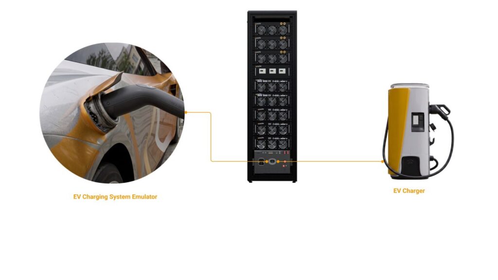
Impedyme’s Charger Box and GridSim Studio validate onboard chargers (OBCs) and the interactions between vehicle, charger, and grid. HIL lets teams test the power-factor-correction (PFC) front-end and DC-DC converter stages against variable grid conditions — voltage sags, frequency variation, and electromagnetic disturbances — and verify compliance-relevant behavior across charging communication standards.
Key charging-system HIL capabilities include:
Because the charger is exercised against an emulated grid and battery, dangerous and hard-to-reproduce grid events — outages, surges, sags — become simple, repeatable test cases.
The Impedyme ecosystem supports the full range of in-vehicle networks — CAN, CAN FD, LIN, FlexRay, SENT, and Automotive Ethernet — with database-driven restbus simulation so that ECUs not yet built are simulated around the device under test. OEM-specific security protocols, including end-to-end (E2E) protection and secure onboard communication, are supported so that security-hardened controllers can be validated realistically.
Impedyme-RT enables requirements-based testing, baseline tests with tolerance bands that compare HIL results against simulated references, version control, and CI integration. Regression suites run automatically whenever firmware changes, embodying the “shift-left” philosophy: the sooner a defect is caught, the cheaper it is to fix. For a software-defined vehicle program running dozens of firmware iterations a week, automated HIL regression is the difference between shipping on schedule and drowning in manual re-testing.
ISO 26262 defines automotive functional safety using a V-model development lifecycle and Automotive Safety Integrity Levels (ASIL) from ASIL A (lowest) to ASIL D (highest), with progressively more rigorous verification demanded at higher levels. For ASIL C and D items, the standard highly recommends fault injection and stress testing under failure conditions — precisely the scenarios HIL reproduces safely and repeatably. A tool-qualified HIL environment supports the traceable audit trail from requirement to verified behavior that a functional-safety case requires. HIL does not replace the safety process, but it is one of the most powerful tools for executing it.
| Subsystem | Impedyme Hardware | Impedyme Software |
|---|---|---|
| BMS | CHP Series, Real-Time Battery Emulator, cell & CMU emulation | BatterySim Studio, PowerHIL Studio |
| Motor / Inverter | CHP Series, RCP-Box, FPGA I/O modules | MotorSim Studio, FPGA Scope |
| Charging / OBC | CHP Series, Charger Box | GridSim Studio |
| Automation / Safety | Impedyme-RT real-time target | Impedyme-RT, Impedyme Simulink Blockset |
The through-line is a single, unified platform: model in a model-based design environment, deploy to Impedyme-RT with microsecond-level synchronization, connect the physical controller through high-speed I/O, then test, validate, and iterate — inject faults, run corner cases, and record everything, all in one closed loop.
Validation of high-voltage electric vehicle powertrains requires strict adherence to functional safety standards, specifically ISO 26262 ASIL-D. The critical role of safety validation is to confirm that the vehicle’s controllers can detect extreme fault conditions, isolate high-voltage systems safely, and transition the vehicle to a graceful, predictable safe state within milliseconds. To achieve this without endangering physical equipment or laboratory personnel, engineers use a dual-layer safety architecture.
Impedyme’s dual-layer safety model, implemented in its HIL Protect Application, splits safety functions into software-configurable and hardware-fixed layers. The first layer consists of software-configurable safety bounds. These parameters are modeled within MATLAB Stateflow, allowing engineers to customize trip thresholds and timing delays depending on the specific test profile. This soft layer prevents nuisance trips from momentary current transients or expected startup spikes, ensuring smooth test execution while maintaining active software-level protection.
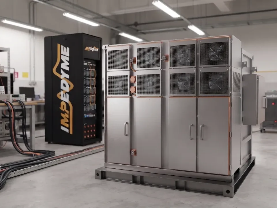
The second layer is the fixed hardware-level safeguard. This layer uses factory-defined, non-configurable analog comparators and high-speed hardware logic gates integrated directly into the physical front-end interfaces of the HIL/RCP-Box and the CHP Cabinet. If current or voltage inputs exceed these fixed physical thresholds, the hardware-level interlock is tripped instantly, bypassing the software layer entirely. Within nanoseconds, the hardware shuts down the physical gate drives of the regenerative power amplifiers, isolating the system. This dual-layer architecture provides a rugged, fail-safe environment, protecting sensitive components and laboratory staff from damage even if the controller software crashes or executes incorrectly.
Using this safety architecture, engineers can safely execute high-risk fault injection scenarios :
First, thermal runaway and cell imbalance emulation dynamically modifies a cell’s emulation parameters, simulating an internal cell short circuit that triggers a rapid temperature rise. The BMS must detect this thermal excursion, initiate cooling protocols, flag the diagnostic trouble code over the CAN FD bus, and open the high-voltage safety contactors before a simulated thermal runaway occurs.
Second, contactor welding and high-voltage isolation failures simulate a welded high-voltage contactor state, where a contactor remains physically closed despite receiving an open command from the supervisory controller. This scenario validates whether the VCU’s safety logic successfully detects the voltage mismatch, flags the welded state, and blocks drive-engagement commands to prevent accidental vehicle movement.
Third, the control plane continuity and auxiliary battery power configuration are tested during catastrophic high-voltage failures. In modern electric vehicles, an independent low-voltage auxiliary pack (typically a 4S lithium configuration) powers the twelve-volt rail. A total failure or isolation shutdown of the high-voltage battery pack (often an 84S configuration) must not collapse the low-voltage domain. By running this scenario in the HIL environment, engineers verify that the independent 4S pack maintains control plane continuity, keeping the vehicle control unit and battery management system active, powered, and in full control to execute a graceful, ordered shutdown and safely log all critical diagnostic error states.
To summarize the engineering tradeoffs and capabilities of modern electric vehicle powertrain validation, the following comprehensive configuration matrix outlines the typical parameters across different subsystems.
| Simulated Subsystem | HIL Platform & Signal Emulation | Core Safety & Fault Validation |
|---|---|---|
| Battery Management (BMS) — Signal-level HIL & Power HIL | Modular isolated emulators & CMDE over SPI; isolated cell voltages, thermistors, shunt current | Thermal runaway, cell imbalance, contactor welding |
| Traction Inverter (MCU) — Power HIL (PHIL) | Combined HIL & Power (CHP) liquid-cooled cabinet; phase current feedback, high-voltage bus tracking | Silicon switch short circuit, overcurrent shutdowns |
| Traction Motor (PMSM/IM) — Power HIL (PHIL) | FPGA-based high-speed motor emulator; multi-channel resolver signals, encoder pulses | Rotor overspeed limits, phase-to-ground faults |
| Vehicle Controller (VCU) — Signal-level HIL | HIL/RCP-Box with RealSync expansion; brake/accelerator pedal sensors, gear states | CAN FD communication loss, driver deadman switch |
| Fast Charging (EVSE) — Power HIL (PHIL) | Bidirectional regenerative grid emulator; ISO 15118 PLC modulation, Control Pilot line | Rogue charger overcurrent, protocol handshaking |
The integration of Hardware-in-the-Loop and Power Hardware-in-the-Loop testing is essential for the validation of electric vehicle powertrains. Moving beyond traditional physical-prototype validation methods reduces schedule risks, improves system quality, and lowers development costs. When designing a modern EV validation infrastructure, several critical conclusions and actionable recommendations should guide engineering decisions:
First, choose FPGA-based real-time simulation architectures for all high-frequency switching applications. Standard CPU-based systems lack the processing speed and low latency required to resolve the high-frequency gating signals of modern silicon carbide (SiC) or gallium nitride (GaN) traction inverters. FPGA-driven systems—such as the Impedyme HIL/RCP-Box—achieve sub-microsecond execution steps, reducing PWM timing errors to less than one percent and ensuring accurate closed-loop control validation.
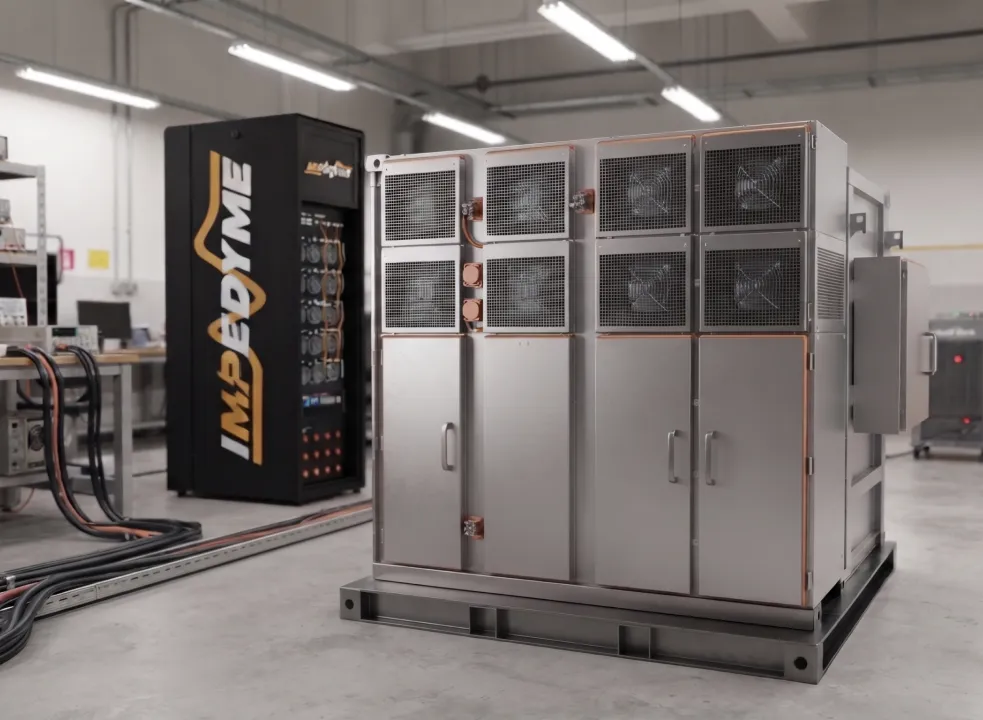
Second, transition systematically from Signal-Level HIL to Power Hardware-in-the-Loop testing as physical power prototypes become available. While CHIL is highly effective for verifying basic control software and communication protocols, it cannot assess the physical power stage, thermal behavior, or physical protection loops under high-voltage, high-current stress. Using a modular, regenerative power system like the Impedyme CHP Cabinet allows engineers to validate physical power stages safely and repeatably.
Third, utilize energy-recirculating architectures to minimize laboratory utility requirements. High-power PHIL validation can consume hundreds of kilowatts of energy. By implementing a circulating power flow configuration, the power can be recirculated within the test cabinet drawers. This configuration reduces laboratory grid energy consumption and cooling infrastructure requirements by up to ninety percent, enabling high-power validation on moderate utility connections.
Fourth, prioritize interface verification and timing stability before running automated test cases. Proceeding straight to test execution without locking in the simulation solver step, sample rates, and signal paths is a major source of erratic test results and false failures. Following a rigorous step-by-step validation workflow guarantees that the HIL platform runs as a highly repeatable, precise scientific instrument.
Fifth, implement a dual-layer safety architecture for high-voltage, high-current validation. Configurable software limits are necessary to prevent nuisance trips during transient conditions, but they must be backed up by independent, hardware-level safeguards. This dual-layer approach protects sensitive controllers and expensive test infrastructure from damage, ensuring safe and reliable operations even under extreme, destructive fault injection scenarios.
By implementing these engineering practices, automotive developers can establish a robust, scalable, and future-proof validation platform. This simulation-first testing methodology empowers engineering teams to deliver electric vehicle powertrains that meet demanding reliability, performance, and functional safety standards.
What is hardware in the loop testing for EV powertrain?
Hardware in the loop testing for EV powertrain connects a real EV controller — such as a battery management system, inverter controller, or onboard charger — to a real-time simulation of the battery, motor, or grid it manages. The controller behaves as though it is wired into a real vehicle, letting engineers validate control logic and protection safely and repeatably before any physical prototype exists.
How does HIL test a BMS without a real battery?
A real-time battery emulator reproduces cell-level electrical and thermal behavior, temperature-sensor signals, and communication buses, so the BMS is exercised exactly as if it were connected to a real pack. Stackable cell-emulation units scale from a single module to a full high-voltage pack, and fault-insertion modules safely reproduce overcurrent, short-circuit, and overtemperature conditions that would destroy real cells.
What is EIS and why does it matter for BMS testing?
Electrochemical impedance spectroscopy (EIS) injects high-frequency signals into a cell and measures the impedance response across a wide frequency sweep. High frequencies reveal ohmic resistance, mid frequencies reveal charge-transfer behavior, and low frequencies reveal diffusion effects. These signatures correlate with state of charge and state of health and detect degradation, letting teams validate BMS estimation algorithms under fast charging and temperature swings.
How does HIL support functional safety and ISO 26262?
ISO 26262 uses a V-model and Automotive Safety Integrity Levels (ASIL A to D), with higher levels demanding fault injection and stress testing under failure conditions. HIL reproduces exactly those scenarios safely and repeatably, and a tool-qualified HIL environment supports the traceable audit trail from requirement to verified behavior that a functional-safety case requires.
Can HIL testing be automated for continuous integration?
Yes. Impedyme-RT supports requirements-based testing, tolerance-band baseline comparisons against simulated references, version control, and CI integration. Regression test suites can run automatically on every firmware change, embodying a shift-left approach that catches defects as early and cheaply as possible.