
Battery module testing card

Application knowledgeGridMotorProduct knowledgeWebinars

Battery module testing header

Battery Module Testing: Ensuring Performance, Safety, and Reliability

Battery module testing sits at the heart of every reliable battery system. Between the individual cell and the finished pack, the module is the level where electrical, thermal, mechanical, and software behaviour first come together — and where most design and manufacturing problems are caught before they become field failures. Whether you are developing an electric-vehicle traction battery, a stationary energy-storage system, or a backup power module, the quality of your battery module testing program directly determines the safety, range, lifetime, and warranty cost of the final product.

This guide explains what battery module testing involves, the parameters and test types that matter, the standards engineers design against, and how modern real-time emulation and Power Hardware-in-the-Loop (PHIL) methods make module validation faster, safer, and more representative of real operation. Throughout, you will see how Impedyme’s FPGA-based platforms — including BatterySim Studio, PowerHIL Studio, and the CHP Testbench — give R&D and production teams a single environment for characterization, emulation, fault injection, and diagnostics.

What Is a Battery Module, and Why Test at the Module Level?

A lithium-ion battery is built up in three tiers. Individual cells are grouped — in series and parallel — into a module, and several modules are assembled into a pack with its battery management system (BMS), contactors, cooling, and high-voltage interfaces. The module is the first level where cells are mechanically clamped, electrically interconnected, instrumented with temperature and voltage sensing, and (in many designs) connected to module-level balancing and monitoring electronics.

Testing at the module level matters because it isolates problems that are difficult or expensive to diagnose later:

  • A single weak or mismatched cell, a high-resistance weld, or a loose interconnect shows up clearly in module data but can be masked once the module is buried inside a full pack.
  • Thermal gradients, sensor placement errors, and cooling-path issues are localized and observable at the module before they propagate.
  • BMS sensing, balancing, and communication can be exercised against known, controlled conditions instead of an unpredictable full pack.

In short, robust battery module testing catches faults at the cheapest possible point in the value chain and gives engineers clean, attributable data for design decisions.

The Key Parameters Measured in Battery Module Testing

Every meaningful battery module testing program revolves around a core set of electrical and electrochemical parameters. Understanding what each one tells you is the foundation of a good test plan.

State of Charge (SoC) — the present charge level relative to capacity, used to anchor performance and aging tests to a known operating point.

State of Health (SoH) — the module’s capacity and capability relative to its beginning-of-life condition; the headline indicator of degradation.

Depth of Discharge (DoD) — how deeply the module is cycled, which strongly influences cycle life.

DC internal resistance (DCIR) — measured by applying a controlled current step and observing the voltage response; rising DCIR signals aging, poor welds, or interconnect problems.

AC internal resistance (ACIR) and electrochemical impedance spectroscopy (EIS) — frequency-domain measurements that reveal the internal electrochemical behaviour of cells and joints far earlier than a simple resistance reading. EIS is one of the most diagnostic tools in modern battery module testing, and it is especially powerful when the measurement instrument is tightly synchronized with the power interface.

Capacity and energy throughput — the usable amp-hours and watt-hours under defined charge/discharge conditions.

Open-circuit voltage (OCV) and cell-to-cell voltage balance — used to verify interconnect integrity and the effectiveness of balancing.

Coulombic and energy efficiency — how much charge and energy is returned on discharge versus what was put in.

Accurate measurement of these parameters depends on good practice at the hardware level — for example, using 4-wire (Kelvin) sensing so that voltage drops across cabling do not corrupt readings, and keeping current control fast and clean so that DCIR and dynamic tests are repeatable.

ParameterUnitPrincipal Measurement TechniqueTechnical Significance for Module Safety & Performance
Open Circuit Voltage (OCV)Volt (V)High-precision digital voltmeter under zero-load equilibriumCrucial for calibrating SoC, estimating cell consistency, and detecting micro-short circuits.
Direct Current Internal Resistance (DCIR)Milliohm (mΩ)High-current pulse profiling (ΔV/ΔI)Identifies faulty welds, busbar connection degradation, and overall power-delivery limits.
Alternating Current Internal Resistance (ACIR)Milliohm (mΩ)Single-frequency AC excitation (typically 1 kHz)Serves as a rapid screening tool for incoming quality control and baseline cell sorting.
State of Charge (SoC)Percentage (%)Coulomb counting combined with dynamic OCV lookupPrevents overcharging or over-discharging by defining operational boundaries.
State of Health (SoH)Percentage (%)Capacity extraction testing and DCIR tracking over timePredicts end-of-life behavior, degradation rates, and secondary-use suitability.
Contact ResistanceMicro-ohm (μΩ)High-sensitivity 4-wire (Kelvin) resistance sensingDirectly assesses weld quality on busbars to prevent localized thermal hotspots.

Key Battery Module Test Categories

Battery module testing covers multiple domains. At a high level, test engineers focus on electrical, thermal, mechanical, and environmental aspects. Common tests include:

  • Electrical Performance: Measure capacity, energy, and power delivery under charge/discharge. Tests typically involve deep and partial cycling at various C-rates to characterize available capacity and efficiency. Engineers also measure internal resistance (DCIR) and perform electrochemical impedance spectroscopy (EIS) to detect changes in cell chemistry and aging. State-of-Charge (SOC) and State-of-Health (SOH) tracking is often embedded in long-term cycling tests. Advanced test benches can even emulate real driving profiles (WLTP, racing, etc.) to see how the module responds in realistic use.
  • Aging and Cycle-Life: Long-duration cycling tests reveal how modules degrade over time. By running thousands of charge/discharge cycles under controlled conditions, engineers track capacity fade, resistance rise, and other wear-out mechanisms. These tests help predict lifetime and establish warranty periods. They often include calendar aging (holding at high/low SOC for weeks) and stressors like elevated temperatures to accelerate life.
  • Safety and Abuse: Safety evaluation is paramount. Modules undergo overcharge and over-discharge tests to ensure protective mechanisms work. Thermal abuse tests (forcing a module toward thermal runaway conditions) check if separators and BMS controls can halt propagation. Short-circuit tests, penetration tests, and nail tests verify fail-safe design. In each case, sensors (thermal probes, smoke detectors) monitor for unsafe reactions. Battery testing standards (UL/SAE/IEC) often specify these abuse procedures.
  • Thermal and Environmental: Temperature greatly affects battery safety and life. Modules are cycled across extreme temperature ranges (e.g. –40°C to +80°C thermal cycling) to test heat management and material robustness. Thermal runway tests deliberately heat cells to observe failure modes. Environmental stress (humidity, high-altitude pressure, salt fog) is applied to ensure modules resist moisture and corrosion.
  • Mechanical and Vibration: Since batteries may experience shocks and vibrations (during vehicle use or transport), modules are tested on shaker tables and drop towers. Vibration profiles simulate bumps and engine shake. Crush and impact tests mimic severe accidents. The goal is to ensure no internal shorts or housing ruptures under mechanical stress.

These categories align with industry-standard protocols. For example, IEC 62660 and UL 1642/2054 require cells/modules to pass short-circuit, altitude, temperature, and drop tests. Automotive-specific standards (SAE J2464, J2929, UL 2580) further mandate abuse tests for EV battery modules. Following these guidelines in module test plans is critical for compliance and safety.

The Main Types of Battery Module Testing

Battery module testing is not a single procedure but a family of tests applied across the product life cycle — R&D, design validation, production, and in-service evaluation. The most important categories are below.

Charge/Discharge and Cycling Tests

Controlled constant-current (CC), constant-voltage (CV), and constant-power profiles characterize how the module sources and sinks energy. Cycling tests repeat these profiles hundreds or thousands of times to quantify capacity fade and resistance growth, building the data set that defines warranty life.

Performance and Dynamic Drive-Cycle Tests

Real loads are not constant. Module testing applies dynamic profiles — acceleration, regenerative braking, fast-charge pulses, and standardized drive cycles — to verify performance under representative operation. Pulse and peak-power tests confirm the module can deliver and absorb the currents the application demands without excessive voltage sag or heating.

Aging, Calendar-Life, and Degradation Tests

Modules are cycled and held at controlled SoC and temperature to study both cycle aging and calendar aging. The goal is to predict end-of-life behaviour and to validate the BMS algorithms that estimate SoH over a decade of service.

Thermal and Environmental Tests

Battery module testing evaluates heat generation, cooling-system effectiveness, and temperature distribution across cells. Combined with environmental chambers, modules are validated across the temperature and humidity envelope of the target application — critical for both automotive and data-center deployments.

Safety and Abuse Tests

Overvoltage, overcurrent, short-circuit, over-discharge, mechanical vibration, and high-voltage isolation tests verify that protection mechanisms work and that the module behaves predictably at its limits. Many abuse scenarios are destructive on real hardware, which is one reason emulation-based methods (covered below) are so valuable for the early exploration of fault behaviour.

BMS Sensing, Balancing, and Communication Tests

The module’s monitoring electronics must report cell voltages and temperatures accurately, balance cells correctly, and communicate over the chosen bus. Module testing compares BMS-reported values against precision reference measurements and exercises the balancing and protection logic under controlled conditions.

Production and End-of-Line (EOL) Tests

On the manufacturing line, faster functional tests confirm interconnect integrity, capacity within tolerance, DCIR consistency, communication, and protection function — screening every module before it enters a pack.

Battery Pack Testing: Validating the Fully Integrated System

A battery pack is the complete, application-ready energy system: multiple modules wired in series and parallel, governed by a master battery management system, joined by contactors and pre-charge circuitry, fed through a liquid- or air-cooling loop, and enclosed in a structural housing with high-voltage connectors and isolation barriers. Battery pack testing validates all of these elements working together as one machine, under the voltages, currents, and thermal loads the product will see in service. Where module testing isolates a group of cells, pack testing confirms that the assembled system behaves safely and predictably as a unit.

For electrified mobility, this is the decisive validation stage. Electric vehicle battery pack testing operates at full traction voltage — commonly 400 V or 800 V architectures delivering hundreds of kilowatts — so the behaviours that matter are not just cell chemistry but pack-level interactions: voltage and resistance distribution across module strings, master-BMS state estimation, contactor and pre-charge sequencing, coolant performance under sustained load, and isolation integrity across the whole high-voltage envelope. Faults that were invisible or contained at the module become system-level safety and performance issues at the pack.

How Pack Testing Differs From Module Testing

Vehicle battery pack testing introduces variables that simply do not exist one tier down:

  • Full-voltage, full-power operation. The pack must source and sink the complete traction current. String-to-string imbalance in voltage, resistance, or capacity surfaces here, where a single weak module can cap the performance of the entire pack.
  • Master BMS and system communication. The pack-level BMS aggregates every module, manages contactors, and reports over CAN, CAN FD, or LIN to the vehicle. Battery pack testing verifies that state-of-charge and state-of-health estimation, balancing decisions, and protection logic remain correct across the assembled system.
  • Thermal management as a system. Cooling is validated as an integrated loop — coolant flow, pump performance, and temperature uniformity across modules under realistic charge, discharge, and fast-charge loads.
  • Structural and ingress integrity. The enclosure must protect against vibration, shock, water ingress (IP rating), and crush, while maintaining electrical isolation from the chassis.
  • Propagation behaviour. Safety evaluation shifts from a single cell to whether a fault in one module can be contained before it propagates across the pack.

Key EV Battery Pack Testing Categories

EV battery pack testing spans the same electrical, thermal, mechanical, and safety domains as module work, but at system scale and full operating voltage:

  • Performance and drive-cycle validation. The pack is exercised with standardized and application-specific drive cycles (WLTP and similar), peak-power and acceleration pulses, regenerative braking, and DC fast-charge sequences to confirm usable energy, power delivery, and voltage stability under realistic vehicle demand.
  • Capacity, efficiency, and range correlation. Full-pack capacity and round-trip energy efficiency are measured to anchor range claims and warranty terms.
  • Thermal and cooling-system testing. Heat generation, coolant effectiveness, and temperature distribution are characterized across the full temperature envelope, including sustained fast-charge thermal load.
  • Safety, isolation, and abuse testing. High-potential (Hi-pot) and insulation-resistance tests verify dielectric strength between the high-voltage system and the grounded enclosure; overcharge, over-discharge, short-circuit, and thermal-propagation tests confirm that pack-level protection and containment work as designed.
  • Environmental and ingress testing. Temperature cycling, humidity, altitude, salt fog, and water-immersion (IP) tests confirm the sealed pack survives its real-world climate.
  • Mechanical testing. Vibration, mechanical shock, and crush testing validate that the enclosure and internal interconnects withstand transport and collision loads without internal shorting.
  • End-of-line and assembly verification. On the production line, electric vehicle battery pack testing confirms interconnect integrity, isolation resistance, BMS communication, contactor function, and capacity within tolerance before the pack ships.
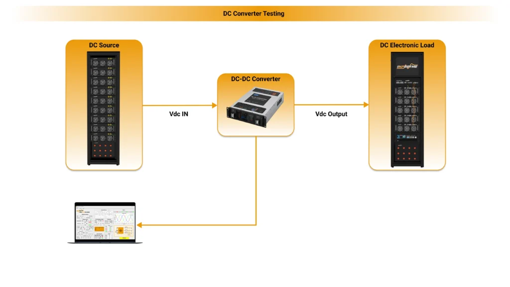
dc dc converter testing impedyme

Standards Governing Battery Pack Testing

EV battery pack testing is anchored by the same families of standards that govern modules, applied at system level: UL 2580 for EV battery systems, IEC 62660 for traction battery performance and reliability, ISO 6469 and ISO 12405 for electric-vehicle safety and pack test specifications, and UN 38.3 for transport. Pack-level certification typically combines these formal procedures with OEM-specific duty cycles that replicate the target vehicle’s real operating profile.

Why Pack-Level Emulation and PHIL Matter Even More

The engineering challenges of physical testing — cost, safety risk, and slow turnaround — scale sharply at the pack level, because the voltages, currents, and energies are far larger. This is precisely where real-time emulation and Power Hardware-in-the-Loop deliver the greatest return. Rather than assembling and cycling a real high-voltage pack to validate an inverter, on-board charger, or vehicle controller, engineers route a real-time pack model through a bidirectional, regenerative converter that sources and sinks genuine current and voltage at full traction levels. Impedyme’s CHP Testbench supports high-power tests up to the megawatt scale and high-voltage operation into the thousands of volts, so a complete electric vehicle battery pack can be emulated — including aging, imbalance, and fault conditions — without staging volatile cells. Because the interface is regenerative, the facility supplies only system losses rather than full pack power, which makes high-power vehicle battery pack testing far cheaper and safer to run.

Feature / MetricConventional Battery CyclerImpedyme CHP Real-Time Battery Emulator
Operational DefinitionCharges and discharges physical battery modules under specific electrical profiles.Replicates the electrical and thermal behavior of virtual batteries using high-speed power electronics.
Testing TargetPhysical cells, modules, and packs (evaluating physical degradation and capacity).Connected hardware sub-systems, such as BMS, traction inverters, and fast-charging interfaces.
Response LatencyTypically millisecond-range control loops, limited by the power stage and communication interfaces.Sub-microsecond execution loops, with step times as low as 90 nanoseconds on FPGA-based processors.
Safety Risk ProfileHigh; physical batteries are vulnerable to thermal runaway, cell venting, and electrical fire.Low; all abusive battery behaviors are virtualized, eliminating physical hazards during testing.
RepeatabilityLow; physical degradation during cycling continuously alters the battery’s baseline performance.High; the virtual battery state can be instantly reset to identical charge, temperature, and health states.
EIS IntegrationRequires external spectrographic analyzers and long diagnostic measurement windows.Native, multi-channel EIS using simultaneous PRBS or multisine excitation in real time.

Testing Equipment and Techniques

A variety of specialized hardware is used for module testing. In practice, test engineers assemble a battery test system consisting of: high-power bidirectional sources (electronic loads/channels), environmental chambers, data acquisition, and control software. Key elements include:

  • Battery Cyclers/Test Stands: These are multi-channel charge/discharge systems that can precisely source or sink high currents and voltages. Typical module testers offer adjustable voltages (e.g. 20–400 V) and currents (up to hundreds of amperes) with fast switching between charge/discharge. Advanced cyclers use regenerative technology to return discharged energy to the grid, improving efficiency. They provide high-accuracy measurements (voltage to ~0.01% FS, current sampling at >50 kHz) to detect small performance changes. Many systems allow parallel channels, so modules of any size can be tested by combining modules.
  • Emulators and Simulators: Instead of or in addition to real batteries, battery emulators simulate the electrical behavior of modules in real time. These bidirectional power supplies can mimic a module’s voltage, internal resistance, and dynamic response under charge/discharge, without actual cells. Emulators are invaluable for testing chargers, BMS, or vehicle electronics safely and repeatably, as they eliminate risks like thermal runaway and remove limitations of slow charging. Impedyme’s Battery Emulator, for example, precisely reproduces a battery’s characteristics and supports high-voltage operation (thousands of volts) for full-scale pack simulation.
  • Environmental Chambers: Temperature–humidity chambers house modules during tests to control ambient conditions. Chambers enable thermal cycling (-40–85 °C and beyond), humidity exposure, and altitude (reduced-pressure) tests. Combined with hardware-in-loop (HIL) control, a chamber can reproduce real-world climate profiles while modules are electrically cycled.
  • Mechanical Test Rigs: Shaker tables and shock machines apply vibration and impact according to automotive standards. These are often used in sync with electrical cycling (e.g. cycling while vibrating) to find faults that only appear under simultaneous stress.
  • Data Acquisition and Sensors: Modern module tests log hundreds of channels: individual cell voltages, temperatures, currents, pressures, and digital BMS signals. High-speed DAQ cards and synchronized sampling capture transient events. To ensure accuracy, 4-wire (Kelvin) sensing is used for voltage measurement, compensating for wire drops. This precision is vital when testing large modules, as even small voltage errors can skew capacity calculations.
  • Software and Control: Test execution is automated via sophisticated software. Typical features include programmable charge/discharge profiles (constant current, constant voltage, pulse power), event triggers (e.g. stop on over-temperature), and data analysis tools (capacity calculations, aging curves). Integration with Simulink or LabVIEW is common for custom protocols. Software may also perform impedance analysis (EIS) in situ, injecting sine-wave or multi-sine signals during pauses in cycling.

Regardless of equipment, a key goal is safety during testing. Test stands incorporate interlocks, ground-fault monitors, and emergency disconnects. Multi-layered protection (hardware over-voltage/current cut-offs, fuses, BMS software limits) is standard. In high-voltage setups, isolated communication (optical links) and safe interfaces are used to protect operators. Overall, the testbench must reproduce realistic load and charge conditions while ensuring that any fault remains contained and logged for analysis.

Batteries Standards and Compliance

Battery modules must meet a wide array of standards before being deployed. Key examples include:

  • UL and SAE Standards: Standards like UL 2271 (light electric vehicles) and UL 2580 (EV battery systems) define safety and performance tests for modules and packs. For instance, UL 2580 requires tests for short circuit, overcharge, forced discharge, vibration, and fire exposure. SAE standards (J2464 for abuse testing, J2380 for vibrations) add automotive-specific protocols. Manufacturers typically need to certify modules/pack assemblies under these frameworks to sell into EV markets.
  • International Electrotechnical Commission (IEC) Standards: IEC 62660 (parts 1–3) covers traction battery cells/modules – specifying tests for cycle life, abuse, calendar life, and reliability. IEC 62133 applies to portable secondary cells (often cited for modules in portable/industrial use). Many projects voluntarily test to IEC specs even if local regulations differ.
  • Transportation Standards: Modules must pass UN 38.3 (or IEC 62281) tests for transport, including mechanical shock, thermal, vibration, and humidity, ensuring safe shipping. Modules may also require certification (e.g. CE, UL, KC, PSE marks) for international sale, which involves meeting local performance tests.
  • Industry Best Practices: Beyond formal standards, industry groups publish best-practice guides (e.g., UL’s Battery Safety Council recommendations). These emphasize comprehensive module testing, continuous monitoring (BMS certification), and risk mitigation. Following these leads to additional test cases, like separator puncture or fire propagation assessments.

Meeting these standards typically involves a mix of off-the-shelf tests and custom procedures. Test labs and OEMs often tailor test sequences to match real usage scenarios (for example, replicating a vehicle’s duty cycle or environmental conditions). In all cases, thorough documentation and traceability are essential for regulatory approval.

End-of-Line Manufacturing and Weld Quality Diagnostics

In high-volume battery assembly facilities, battery module testing at the End-of-Line (EOL) stage is critical to ensure both initial quality and long-term durability. At this phase, testing centers on verifying the mechanical integrity of connections and the consistency of the integrated cells.

Weld Resistance and Connection Integrity

Modern battery modules are constructed from hundreds of individual cells connected in series and parallel configurations using thin busbars. The physical joints, typically completed using laser or ultrasonic wire welding, must have low resistance to prevent localized voltage drops and heating.

Automated End-of-Line (EOL) test systems use high-sensitivity 4-wire DC resistance meters to measure contact resistance across each joint. Any weld spot displaying a deviation from the standard micro-ohm range indicates a weak or faulty joint, allowing the system to flag the module for rework before it is integrated into a complete battery pack.

Dielectric Withstand and Isolation Testing

Safety verification at the EOL stage requires high-voltage isolation testing. High-potential (Hi-pot) testing applies a high voltage between the module’s active electrical circuits and its grounded outer frame or housing to verify dielectric strength and measure isolation resistance. This test ensures that the internal insulation materials have not been damaged during assembly, mitigating the risk of short circuits or electric shock hazards during vehicle operation.

BMS Calibration and Communication Verification

The EOL test sequence also validates the functionality of the Battery Management System (BMS). Automated systems simulate dynamic cell balancing sequences, verify sensor calibration (such as thermistors and current shunts), and check communications over interfaces like CAN, CAN FD, or LIN. This ensures that the BMS can accurately monitor cell voltages and temperature profiles prior to final product delivery.

Real-Time Emulation and PHIL: A Faster, Safer Approach

A battery emulator replaces a physical module with a real-time model that behaves electrically like the real thing — delivering and absorbing genuine current and voltage at the terminals of the device under test, while a high-fidelity model computes the module’s response moment by moment.

There are two complementary modes:

  • Hardware-in-the-Loop (HIL): the model provides signal-level sensor values to a BMS or controller, letting you validate firmware and estimation algorithms before any power hardware — or even silicon — is available.
  • Power Hardware-in-the-Loop (PHIL): the real-time model is routed through a bidirectional, regenerative power converter so the emulated module sources and sinks real power. This lets engineers validate a BMS alongside contactor, pre-charge, on-board charger, DC-DC converter, and motor-inverter behaviour under production-level electrical conditions — without staging a real battery.

The advantages for battery module testing are direct: a digital twin runs in minutes what takes days on a physical module; shorts and abuse cases are explored safely without destroying cells; emulated modules let BMS firmware be validated against ISO 26262 fault-injection needs before hardware exists; and inverters and chargers can be exercised at full power without assembling real modules. Regenerative power interfaces also recirculate energy internally, so the facility only has to supply system losses rather than full test power — dramatically cutting the grid connection and running cost of high-power testing.

How Impedyme Accelerates Battery Module and Pack Testing

Impedyme builds FPGA-based real-time emulation and PHIL platforms designed specifically for power-electronics and battery validation. The result is a single ecosystem that takes a battery module and pack testing program from characterization through emulation, fault injection, and diagnostics — without moving data between disconnected tools.

BatterySim Studio — Battery Emulation and Module Modeling

BatterySim Studio is Impedyme’s battery simulation and emulation software, purpose-built for the validation and emulation phase rather than offline design alone. It runs a battery model on Impedyme’s FPGA-based CHP platform with model steps as low as 90 ns, so the emulated module responds with the dynamics of a real one. Engineers get real-time insight into SoC, voltage, and impedance; can model aging, temperature, and degradation behaviour; and can build custom models that reflect real-world operation across chemistries. In HIL mode it supplies signal-level values to a BMS out of the box; in PHIL mode it delivers real current and voltage to the device under test, enabling EIS and impedance-aware testing in converter-coupled environments.

PowerHIL Studio — Orchestration, Automation, and Diagnostics

PowerHIL Studio is the software environment that configures, controls, and automates real-time HIL and PHIL tests. It offers prebuilt modules for grid, motor, battery, and impedance emulation; runs on FPGA or CPU with parallel mode for higher power and slave mode for synchronized multi-unit setups; and requires no FPGA programming. Test scenarios can be built in a GUI or imported from Simulink, executed with on-the-fly parameter tuning and fault injection, and analyzed with automated logging, an FPGA Scope for high-resolution diagnostics, and built-in reporting. MATLAB scripting lets teams script parameter sweeps, capture data, and generate reports with no manual intervention — ideal for repeatable, auditable battery module and pack testing campaigns.

CHP Testbench — High-Power PHIL Hardware

The CHP Testbench integrates HIL and PHIL in one regenerative, FPGA-based platform that emulates realistic charge/discharge cycles using individual voltage–current (V-I) profiles and assesses module performance under varied thermal and load conditions. Because power is circulated internally through the regenerative interface, high-power module and pack testing can be performed without a dedicated high-power grid feed. The platform mirrors MATLAB/Simulink models for high-power tests up to the megawatt scale and bandwidths up to 20 kHz — connect the optical links to the cabinet, deploy the model, and begin testing. Its megawatt-scale, thousands-of-volts capability makes it well suited to full electric vehicle battery pack testing at 400 V and 800 V architectures.

Charger Box and the Wider Ecosystem

For teams whose battery module and pack testing intersects with charging and grid behaviour, Impedyme’s Charger Box, GridSim Studio, and MotorSim Studio extend the same platform to validate on-board chargers, DC fast-charge interactions, grid profiles, and full EV drivetrain scenarios — so a module or pack can be tested not in isolation but as part of the system it will actually live in.

Strategic Engineering Recommendations for Battery Module and Pack Testing

Implementing a rigorous and future-proof validation program requires several systematic steps:

  • Consolidate Software Toolchains: Avoid using fragmented tools for simulation, modeling, and physical testing. Adopting unified workspaces like BatterySim Studio integrates real-time emulation, EIS analysis, and BMS testing into a single workspace, reducing data transfer overhead and shortening development timelines.
  • Unify Physical and Virtual Methods: Use high-speed real-time emulation alongside targeted physical testing. Emulating complex operating profiles on FPGA-based platforms with sub-microsecond step times allows for extensive safety and boundary validation without mechanical or thermal risks.
  • Apply Continuous EIS Diagnostics: Supplement traditional DCIR and ACIR checks with multi-channel EIS diagnostics. Simultaneous multisine or PRBS excitation provides continuous data on the module’s electrochemical state, enabling early detection of internal defects like lithium plating or connection degradation.
  • Implement High-Efficiency Regenerative Systems: Specify bidirectional, regenerative power stages with high grid-return efficiencies. This design significantly reduces operational energy consumption and minimizes laboratory cooling requirements.
  • Design Multi-Layered Safety Controls: Ensure testing setups include independent safety mechanisms at the software, firmware, and hardware levels. Synchronizing BMS status reports with the primary cycler interface over high-speed networks like CAN or CAN FD ensures fast, automatic shut-offs during anomalous operation.

Combining advanced physical test benches with high-fidelity real-time emulation allows engineering teams to perform comprehensive, repeatable, and safe validation. This integrated approach ensures compliance with international standards, optimizes module and pack performance, and accelerates development across electrified industries.

Frequently Asked Question

What is the difference between battery module testing and pack testing? 

Module testing validates a group of interconnected cells — their electrical integrity, thermal behaviour, and module-level monitoring — while pack testing validates the fully integrated system including the BMS, contactors, cooling, and isolation. Module testing catches faults earlier and at lower cost.

Which parameters are most important in battery module testing? 

Capacity, DCIR, EIS/ACIR, SoC, SoH, cell-to-cell voltage balance, and thermal behaviour are the core indicators. Together they describe performance, aging, and safety.

Can you test a battery module without a physical module? 

For a large part of the program, yes. A battery emulator such as BatterySim Studio running on Impedyme’s FPGA-based CHP platform reproduces the module’s electrical behaviour in real time, allowing BMS firmware, chargers, and inverters to be validated before — or instead of — staging real modules for every test.

How does PHIL make battery module testing safer? 

PHIL lets you explore shorts, over-current, and abuse scenarios on an emulated module instead of a real one, removing the danger and destruction associated with physical abuse testing while still delivering real power to the device under test.

What does EV battery pack testing involve?

Electric vehicle battery pack testing exercises a full traction pack at operating voltage — 400 V or 800 V architectures — using drive-cycle and peak-power profiles, fast-charge sequences, thermal and cooling-system characterization, isolation and Hi-pot safety checks, environmental and ingress tests, and mechanical vibration and shock. It also validates master-BMS communication, contactor sequencing, and protection logic across the assembled system.