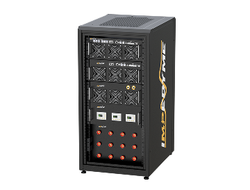
Impedyme FPGA Scope
系统 Impedyme FPGA Scope is a built-in, high-speed signal visualization and diagnostics tool engineered specifically for Impedyme’s CHP Series real-time simulation platforms. Deeply integrated into Impedyme’s FPGA-centric real-time control and signal-processing architecture, the FPGA Scope enables engineers to monitor, trigger, and analyze critical electrical and control signals with sub-microsecond resolution — all without external oscilloscopes or DAQ hardware.
This tight FPGA integration makes the Impedyme FPGA Scope a core differentiator for advanced 电力硬件在环(PHIL), Controller HIL, and grid-compliance validation workflows.
Purpose and Use Case
In modern HIL and PHIL testing environments, engineers face increasing system complexity, higher switching frequencies, and stricter compliance requirements. Traditional software-based scopes or external instruments often fail to capture true real-time behavior.The Impedyme FPGA Scope is purpose-built to address these challenges by allowing engineers to:
1
Observe internal system states (Id/Iq, Vabc, Vdq, controller states, integrator outputs)
2
Validate timing-critical signals (PWM edges, PLL lock behavior, fault logic response)
3
Troubleshoot control algorithm performance in real time
4
Analyze transient events, fault ride-through, and grid disturbances
Engineering Challenges Solved by Impedyme FPGA Scope
Modern power electronics and real-time simulation environments introduce engineering challenges that traditional measurement and debugging tools struggle to address. The Impedyme FPGA Scope is specifically designed to solve these problems by providing deterministic, FPGA-level visibility into fast, timing-critical systems. Below are the most common engineering challenges and how Impedyme’s FPGA Scope overcomes them.
1. Missed Transient Events in High-Speed Systems
Challenge:
Fast transients like voltage dips, switching spikes, or fault triggers can occur within microseconds and are often missed by external tools.
Solution:
-
- Captures signals directly inside the FPGA execution path
- Sub-microsecond time resolution
- Pre-trigger and post-trigger event capture
2. Control Loop Instability and Tuning Issues
Challenge:
Control loops may become unstable due to timing mismatches, saturation, or integrator windup.
Solution:
- Access to internal controller states
- Real-time comparison of reference and feedback signals
- Live tuning with instant waveform validation
3. PHIL Loop Oscillations and Stability Problems
Challenge:
Power Hardware-in-the-Loop setups can experience oscillations caused by latency or impedance mismatch.
Solution:
- Deterministic capture synchronized with PHIL timing
- Simultaneous monitoring of voltage, current, and impedance signals
- Trigger-based capture during instability events
4. PWM Jitter and Switching Debugging
Challenge:
High-frequency PWM signals require precise timing analysis to detect jitter or duty-cycle distortion.
Solution:
- FPGA-level visibility of PWM timing
- High-resolution switching-cycle analysis
- Accurate transition timing measurements
5. Synchronization Across Control and Simulation Domains
Challenge:
Timing misalignment between control logic and simulation models can affect testing accuracy.
Solution:
- Signals captured within the same real-time clock domain
- Deterministic synchronization with simulation steps
- Time-aligned waveform capture
6. Limited Visibility Into Internal FPGA Signals
Challenge:
Traditional tools often cannot access internal FPGA signals during real-time operation.
Solution:
- Direct monitoring of internal FPGA variables
- Real-time signal inspection without external probes
- Improved debugging of embedded control logic
Architecture Overview
The FPGA Scope is not a post-processing tool — it is embedded directly inside the real-time signal path on the FPGA/DSP hardware used for simulation and control. This offers several advantages:
| 功能 | 优势 |
|---|---|
| Zero-latency capture | Observes waveforms directly from FPGA buses and DSP registers |
| High-speed sampling | Capable of sampling at hundreds of kHz to MHz range |
| Trigger-based acquisition | Capture events around overvoltage, current spikes, PWM changes |
| Non-intrusive observation | No performance loss, unlike traditional CPU-based visualization |
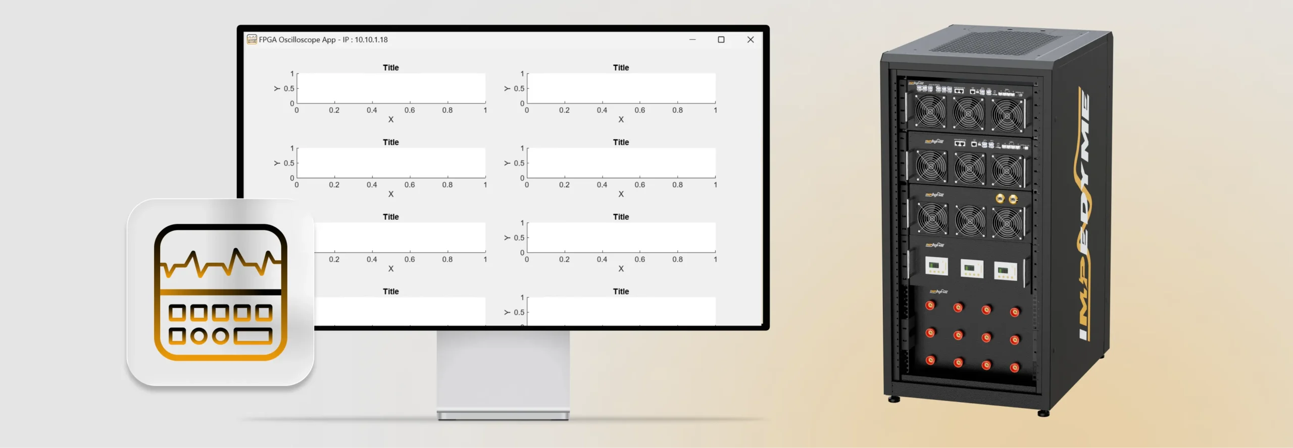
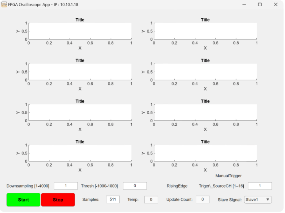
User Interface Features
Application Examples
1
Controller Debugging
2
IEEE 1547 Fault Response
3
PHIL Stability Validation
Using FPGA Scope for Grid Code Compliance & Certification Testing
In modern power systems, grid code compliance and certification testing are critical for inverters, converters, and other distributed energy resources. Meeting standards such as IEEE 1547, UL 1741, and IEC 61850包 LVRT/HVRT requirements, demands precise, deterministic measurement of electrical signals under real-time conditions. The Impedyme FPGA Scope provides the high-resolution, hardware-integrated visibility necessary for these tests.
Key Advantages
| 功能 | 优势 |
|---|---|
| Fully FPGA-integrated | True real-time scope capture; no CPU lag |
| High-Speed & High Resolution | Captures detailed waveform dynamics |
| Trigger-Based Events | Capture specific faults, overshoots, or disturbances |
| Multichannel View | Overlay voltage, current, and control signals |
| Export-Ready | Generate test reports instantly |
| Safe and Isolated | Eliminates need for physical probes on high-voltage hardware |
Performance Capabilities of Impedyme FPGA Scope
系统 Impedyme FPGA Scope is engineered to meet the stringent performance demands of modern power electronics, real-time simulation, and PHIL/HIL testing. Its capabilities are defined not just by features, but by measurable, deterministic performance metrics that engineers can rely on during validation, debugging, and certification workflows.
Below is a clear breakdown of the key performance characteristics that set the Impedyme FPGA Scope apart.
1
Time Resolution
Sub-microsecond (µs) resolution enables precise capture of fast transients, switching events, and control-loop dynamics.
2
Signal Channel Capacity
Supports up to 16 simultaneous channels for monitoring voltages, currents, PWM signals, controller states, and internal variables.
3
Trigger Response Time
Deterministic FPGA-level triggering provides immediate event detection without software latency.
4
Sampling Synchronization
Cycle-accurate synchronization with the real-time simulation step ensures waveform integrity and timing precision.
5
Maximum Observable Switching Frequency
Accurately captures high-frequency PWM and switching behavior for advanced SiC and GaN converter applications.
6
Data Buffer Depth & Capture Duration
Ready to see FPGA Scope in action?
Join power electronics engineers and HIL test teams using Impedyme's FPGA-integrated scope for sub-microsecond signal visibility — no external instruments needed.