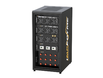

Hardware in the Loop
Hardware in the loop is a real-time testing method that keeps a real controller running its production software while the physical plant it controls is replaced by a high-fidelity, real-time simulation. At Impedyme, we build FPGA-based hardware in the loop and Power Hardware-in-the-Loop platforms that close the gap between offline simulation and field deployment for power electronics. This guide explains what hardware-in-the-loop is, how a HIL simulator works, why the simulation time step matters so much for switching converters.
What is hardware in the loop?
Hardware in the loop is a real-time simulation technique in which a real electronic controller — the device under test — stays physically in the loop, while the plant it normally commands is replaced by a mathematical model running in real time. The controller exchanges real electrical signals through real input and output channels, so it behaves exactly as it would in the field.
That definition carries a lot of weight, so let us unpack the two ideas at its core. The device under test (DUT) is the real, physical piece of hardware you want to validate. In power electronics this is almost always a controller — an inverter control board, a battery management unit, a grid-converter controller, or a motor drive — running the same firmware it will run in production. Nothing about the DUT is simulated; it is the genuine article.
"The loop" is the closed cycle of cause and effect between that controller and its environment. In the real world, a controller reads sensor signals, decides what to do, and drives actuators; the actuators change the physical system; the sensors report the new state; and the cycle repeats thousands of times per second. In a hardware-in-the-loop setup, we cut that cycle open and insert a real-time model where the physical world used to be. The model computes how the plant would respond, feeds those responses back to the controller as real voltages, currents, and digital signals, and reads the controller's commands back in — all fast enough that the controller cannot tell it is talking to a simulation rather than to copper and iron.
This is what separates hardware in the loop from ordinary desktop simulation. In a pure software model, everything is virtual, including the controller. In a hil hardware in the loop arrangement, the controller is real and only its surroundings are modelled. That distinction is the whole point: it means the code you validate is the code you ship, the timing you measure is the timing you get, and the interface behaviour you observe is the interface behaviour that will exist on the bench and in the field.
The hardware in the loop meaning is therefore best understood as a spectrum position. It sits at the far, hardware-rich end of the model-based design progression — model-in-the-loop, software-in-the-loop, and processor-in-the-loop all come first, each adding a little more realism — and hardware in the loop is where the real controller finally meets a real-time world. It is the last validation stage before you connect to real power, and for many programmes it is the most revealing. Because the controller is genuine and the loop runs in real time, hardware in the loop testing surfaces integration problems — timing races, interface faults, protection mis-trips — that no offline model can show.
Hardware in the loop testing: the HIL test workflow step by step
Hardware in the loop testing is the disciplined process of exercising a real controller against a real-time plant model and asserting pass or fail against defined criteria. A good HIL testing programme is not ad-hoc probing; it is a repeatable workflow that produces traceable evidence. Here is how a hardware in the loop test typically unfolds from start to finish.
Build or import the plant model
Start with a model of the physical system — the motor, converter, battery, or grid — that captures the dynamics you care about. Most teams author this in a Simulink-style modelling environment and reuse the same model they already trust from offline design work.
Prepare the model for real-time execution
Convert the model so it can run deterministically on the real-time target, choosing the solver and time step that match the fastest dynamics in the system. For a switching converter, this is where FPGA execution becomes essential.
Map the input and output
Assign the model's signals to physical channels — analogue outputs that emulate sensors, digital inputs that capture gate commands, encoder and resolver emulation, protection lines, and communication buses.
Wire the DUT to the HIL interface
Connect the real controller to the simulator through a breakout and signal-conditioning layer so voltage levels, isolation, and grounding are correct on both sides.
Define the hardware in the loop test cases
Specify initial conditions, the stimulus to apply, and the numeric pass/fail rule for each scenario, including normal operation, boundary conditions, and fault injection.
Run the closed-loop HIL test
Execute each case in real time, letting the controller and model interact while high-speed logging captures every relevant signal.
Assert results and log evidence
Compare measured behaviour against the pass/fail criteria automatically, and store the results with configuration and firmware identifiers so any run can be reproduced later.
Automate and regress
Fold the passing cases into an automated regression suite that reruns on every firmware change, so a fix in one area cannot silently break another.
What You Can Test With Hardware in the Loop
Hardware in the loop validates controllers, power electronics, batteries, motors, and complete electrical systems under realistic conditions. By combining real hardware with real-time simulation, engineers can safely reproduce normal operation, transients, faults, and edge cases before full-system deployment.
EV powertrains and traction inverters
A traction inverter is where high current, fast switching, and safety-critical control all meet. With hardware in the loop, we run motor and battery models on FPGA fast enough to resolve SiC switching, emulate resolver and encoder position, exchange CAN and automotive Ethernet traffic, and read gate commands back in real time. That lets teams probe deadtime distortion, field-weakening transitions, six-step and overmodulation entry, and regenerative braking — safely, repeatably, and long before a dynamometer cell is free. Signal-level checks catch the logic; power-level emulation applies genuine load so the diodes and switches are exercised under true conditions. Explore our approach to automotive HIL testing.
BMS and battery packs
A battery management system is hard to test because faults you must verify — cell short, overvoltage, thermal runaway — are exactly the ones you cannot safely stage on a real pack. Hardware in the loop solves this with cell emulation: the simulator reproduces the electrical behaviour of every cell, and the BMS reads voltages, currents, and temperatures it believes are real. Engineers inject shorts, drift, and imbalance programmatically, run charge and discharge profiles for weeks unattended, and validate state-of-charge and state-of-health estimation against a known ground truth. See how we handle battery management system validation.
Motor drives and motor control
Validating a motor controller has become the central gate for drive development, and hardware in the loop testing is what makes it safe and thorough. Our motor emulator reproduces PMSM, induction, BLDC, and IPM machines with nonlinear effects — magnetic saturation, hysteresis, torque ripple — and angle-dependent flux and torque maps, all updating at nanosecond-scale steps. The controller sees realistic back-EMF, position feedback, and current waveforms, so teams can tune current loops, verify fault handling, and cover operating points that would be risky or slow on a physical dynamometer.
Solar and grid-tied inverters (grid code conformance)
Grid-tied inverters must ride through voltage and frequency disturbances and support the grid rather than trip and worsen an event. Hardware-in-the-loop lets us stage those disturbances on demand — sags, swells, frequency excursions, rate-of-change events, and low-impedance faults — and confirm the inverter's response against grid-code and interconnection requirements automatically, at the exact boundaries of the permitted envelope. Repeatable, programmable scenarios turn weeks of certification prep into an automated campaign.
Microgrids and renewables
A microgrid is a system of controllers — inverters, storage, protection relays, and a supervisory controller — that must cooperate through islanding, resynchronisation, and fault events. Hardware in the loop testing lets us bring the real controllers together against a real-time model of the network, validating protection coordination and energy management before anything is energised in the field. Because the model runs on FPGA, switching-level converter behaviour and slower grid dynamics coexist on one platform. Discover HIL testing for microgrids and renewables.
HVDC
High-voltage DC converter stations use modular multilevel converters with thousands of submodules, and their control and protection replicas must be validated exhaustively before a factory acceptance test. Hardware-in-the-loop is the accepted method: the converter valve is solved on FPGA at sub-microsecond steps while the surrounding AC system runs on the processor, and the manufacturer's real control replicas are exercised through start-up, AC and DC fault ride-through, and contingency modes.
DC fast charging
A fast charger is a power converter and a communicating node at once, so it must be validated on both fronts. With hardware-in-the-loop we emulate the vehicle side — battery behaviour and the charging state machine — while exercising the charger's high-level communication, control-pilot and proximity signalling, and its power conversion under realistic and faulted conditions. That proves interoperability and safe sequencing before a real vehicle is ever plugged in. Explore DC fast charger and EV testing.
eVTOL and electric aircraft
Electrified aircraft move high-voltage DC, power-dense inverters, and distributed propulsion to the heart of the vehicle, where every failure mode interacts and certification is unforgiving. Hardware-in-the-loop supports the requirements-based verification these programmes demand, letting engineers validate flight-critical power electronics and propulsion controllers against failure scenarios that would be catastrophic to stage in flight. The same platform scales from a single propulsion unit to a full system-level rig.
Shipboard and marine power
Modern vessels run zonal medium-voltage power systems that resemble microgrids, mixing generation, conversion, storage, and propulsion loads on a common bus. Power hardware in the loop gives naval and commercial designers a safe, flexible way to study fault management, power management, and stability in these architectures before committing to steel. Controllers and protection devices are validated against a real-time model of the ship's electrical plant. See how we support marine and shipboard power systems.
Robot controllers and data centre power
Robot and servo controllers can be validated against a real-time model of the manipulator and its drives, with encoder emulation and torque behaviour reproduced faithfully so control logic is exercised without risking a physical arm. Data-centre power is the fast-growing frontier: UPS controllers, battery systems, generator controls, and energy-management systems must ride out AI-driven load swings and grid disturbances with zero downtime, and hardware in the loop validates the whole power chain in a controlled, repeatable loop. Explore data-centre power stability testing.
How does a hardware in the loop simulator work?
A hardware in the loop simulator works by solving a plant model in real time and exchanging that model's state with a real controller through a physical input and output layer, fast enough and deterministically enough that the controller responds as if it were connected to the real system. Three things have to be right for a hil simulator to be credible: the model, the I/O, and the timing. Get any one wrong and the hardware in the loop simulation quietly stops representing reality.

The real-time plant model and the fidelity-versus-speed trade-off
The heart of any hardware in the loop simulation is the plant model. It has to be detailed enough to reproduce the behaviour that matters — switching ripple, torque ripple, fault transients — yet lean enough to solve within the time budget of a single simulation step. This is the fidelity-versus-speed trade-off, and it is unavoidable. A richer model with more states and finer device physics is more faithful but takes longer to compute; a coarser averaged model computes faster but can hide the exact edge case you are chasing. The art of hil simulation is choosing a model that keeps the physics you need while fitting inside a step small enough to stay real-time.
The Input and Output Layer in Hardware in the Loop
The I/O layer is where the model meets the metal. A capable hardware in the loop simulator provides analogue inputs and outputs to emulate sensor signals and read references, digital I/O to exchange logic-level commands, PWM capture to read the controller's gate signals at high resolution, and encoder or resolver emulation so a motor controller sees realistic position feedback. It also provides protection signals — the trip and enable lines that safety logic depends on — and communication interfaces such as CAN, CAN FD, EtherCAT, Modbus, and fibre or SFP optical links. Those fibre links matter especially at power, where a fast, low-latency digital connection between the simulator and a power interface keeps the loop tight. Our Power HIL modules provide multi-channel analogue I/O at high sample rates and 16-bit resolution, high-speed waveform logging, and several optical ports per module for deterministic synchronisation across units, so a bench can scale to hundreds of channels while holding nanosecond-level timing.
Time step, latency, and determinism — and why an overrun invalidates a result
Every real-time simulator advances its model in fixed increments called the time step. On each step it must read inputs, solve the model, and write outputs before the clock ticks to the next step. If it computes one step in less wall-clock time than the interval that step represents, the loop stays honest. If it ever takes longer — an overrun — the illusion breaks and the test is invalid, because the simulated world has fallen behind the real controller talking to it. This is why determinism matters more than raw throughput: a simulator that is fast on average but occasionally overruns will make fault logic look random and erode confidence in every result. A hardware in the loop result is only trustworthy if every single step met its deadline.
Concrete step-size classes tell the story better than the phrase "real time." For power system and grid models, a time step in the region of 50 microseconds is generally sufficient to simulate electrical grid elements faithfully, whereas an accurate power-electronic simulation with a PWM control strategy should generally run under one microsecond. Power electronic converters live in a much faster world. CPU-based simulators typically operate with fixed steps somewhere between roughly 10 and 100 microseconds, and that is simply too coarse for pulse-width-modulated converters: at a 100 kHz switching frequency the entire switching period is only 10 microseconds, so a 10-microsecond step yields barely one model update per switching period, producing severe PWM quantisation errors, distorted duty-cycle measurements, and artificial numerical instabilities. Worse, multiple switching events can fall inside a single coarse time step, so the simulator never even sees them.
Why FPGA-based solving matters for high switching frequencies
The way out of that trap is to solve the model on a field-programmable gate array. A CPU executes model equations more or less sequentially, sharing its cycles across tasks and introducing jitter. An FPGA solves the model in massively parallel logic, computing many parts of the circuit at the same time and integrating processing and I/O on the same chip. The result is deterministic, jitter-free execution at time steps a CPU cannot reach.
Those steps are what let a hardware in the loop simulator represent a high-switching-frequency converter at all. Published FPGA implementations report a step of around 240 nanoseconds for a two-level inverter driven by 20 kHz PWM (with an 80-nanosecond step for a coupled permanent-magnet machine), steps in the order of 100 nanoseconds for resolving switching-frequency current and voltage ripple, and steps as small as 25 nanoseconds to hold accuracy at a 200 kHz switching frequency. This is exactly the territory where FPGA execution stops being optional and becomes necessary. Our CHP Series runs plant models on FPGA fabric with time steps as low as 90 nanoseconds — on the order of eleven million model updates per second — spanning sub-microsecond switching transients up to the slower electromechanical behaviour of the surrounding grid on a single platform.
Wide-bandgap devices make this non-negotiable. Silicon carbide (SiC) and gallium nitride (GaN) transistors switch far faster and at higher frequencies than legacy silicon; SiC devices turn on in tens to hundreds of nanoseconds and GaN devices can switch in under 10 nanoseconds. To capture a PWM signal cleanly you need to sample it many times faster than it switches, which drives the required simulation step down into the sub-microsecond and nanosecond range — device-level real-time studies of electric-vehicle converters switching up to 100 kHz have resolved detailed switching waveforms at sub-microsecond steps with nanosecond-scale resolution. Only an FPGA-based hardware in the loop simulator can hold that timing while keeping the loop closed with a real controller. Without FPGA-class execution, you simply cannot represent a modern high-switching-frequency converter in real time — the test would be invalid before it began. This is why the right HIL simulator architecture matters for high-speed power-electronic testing, while a deterministic HIL simulator is essential when every simulation step must meet its deadline.

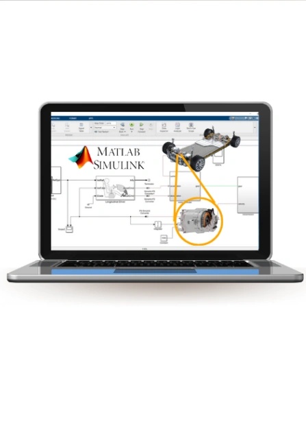



Impedyme HIL system
Our hardware in the loop system is built as one integrated architecture rather than a collection of loosely connected boxes. The design goal is simple: carry a single model from the desktop all the way to full-power validation without ever rewriting it, and orchestrate the whole campaign from one workspace.
At the centre sits the FPGA-based real-time engine that solves the plant model, surrounded by the I/O, signal conditioning, and communication interfaces that connect it to the DUT. Above that hardware runs a software layer that configures the system, deploys the model, sequences the tests, captures the data, and generates the reports. Because these elements are designed together, the hardware in the loop system behaves as a coherent whole: signals defined in the model appear directly on physical channels, and results captured on those channels flow straight back into the modelling environment.
The model import path is deliberately frictionless. Engineers author their plant and controller models in a Simulink-style environment and bring them onto the real-time target through our dedicated blockset, so a model becomes a real-time target without a manual rewrite. This is the practical meaning of a hardware in the loop simulink workflow: the same block diagram you simulated offline becomes the thing executing in real time against your controller, with parameters tunable on the fly and measurements exposed live in the modelling environment.
Our hardware in the loop tools span the full workflow. Configuration and automation tooling sets up the system and scripts entire campaigns; domain-specific studios provide ready-built models for motors, batteries, grids, and drones; a built-in high-resolution scope captures waveforms directly from the FPGA signal path; and a rapid-control-prototyping option lets you develop controller algorithms against a high-fidelity model before any power stage exists. Taken together, these hardware in the loop tools turn a bare real-time target into a complete, software-driven test bench that engineers comfortable with model-based design can drive without hand-writing FPGA firmware.
From Signal to Power: A Complete Testing Workflow
Power electronics validation typically progresses through three key stages:

Signal-Level Testing
Simulating the entire system to validate control electronics in a closed-loop environment.

Power-Level Testing
Incorporating a motor emulator to evaluate both control logic and power-stage hardware.

Mechanical/Dynamometer Testing
Final system validation under actual mechanical loads.
What are HIL industries?
Hardware in the loop (HIL) testing is used across industries where embedded controllers, power electronics, and control software need to be validated under realistic operating conditions. By connecting real hardware to a real-time simulation, engineers can perform hardware in the loop test scenarios without relying entirely on physical prototypes. A hardware in the loop simulator provides the real-time environment needed to reproduce complex operating conditions and faults.
1
Automotive & Electric Mobility
HIL is widely used for EV powertrains, traction inverters, motor controllers, BMS, DC/DC converters, and onboard chargers. HIL testing validates hardware and software across normal operation and faults while reducing reliance on physical prototypes.
2
Aerospace
3
Energy & Grid
HIL tests grid-connected inverters, converters, microgrids, energy storage, and renewable-energy systems under changing grid conditions and faults. Hardware in the loop enables safe, repeatable testing.
4
Battery & Energy Storage
HIL reproduces battery behavior without repeatedly using physical cells or packs. Engineers can test SOC/SOH algorithms, charging strategies, protection functions, and abnormal conditions in a controlled environment.
5
Rail & Marine
HIL supports rail traction, electric propulsion, braking, power management, and onboard electrical systems. Real-time simulation enables testing under changing loads, operating conditions, and faults before deployment.
6
Industrial Automation & Robotics
HIL validates motor drives, robotics, PLCs, and automation systems against simulated loads, sensors, and faults. HIL testing enables repeatable validation before physical commissioning.
Signal-Level HIL vs Power Hardware-in-the-Loop (PHIL)
This is the distinction that decides what your validation actually proves, and it deserves full weight. The word "HIL" covers two fundamentally different arrangements, and confusing them is one of the most expensive mistakes a power-electronics programme can make. Understanding how hardware in the loop works at both signal and power levels is essential for choosing the right validation approach.
Controller hardware-in-the-loop (C-HIL): low-voltage signals only
In controller hardware-in-the-loop, the simulator and the DUT exchange only low-power signals. The real-time model feeds the controller measurement-level analogue voltages and currents representing what its sensors would see, and reads back the controller's gate commands, setpoints, and digital outputs. No real power ever flows. C-HIL is superb at what it does: it validates control logic, state machines, communication, protection sequencing, and the quality of the controller's interfaces, and it does so safely and cheaply. What it cannot do is prove how the power stage behaves. Because the controller never drives real current, C-HIL says nothing about thermal behaviour, conduction and switching losses, electromagnetic interference, or the way a real converter interacts with a real source and load impedance. It proves the brain, not the muscle.
Power hardware-in-the-loop (PHIL): real current and voltage through the DUT
Power hardware-in-the-loop closes that remaining gap by putting real power into the loop. A bidirectional, four-quadrant power amplifier sits between the real-time simulator and the DUT, taking the model's low-level signals and reproducing them as real voltage and current at the levels the device actually operates at — and, crucially, sourcing and sinking energy so the DUT experiences genuine electrical loading and regeneration. Now the device under test is stressed the way it will be in service. Only at power do you see the thermal effects of real conduction and switching losses, the electromagnetic interference that real switching edges generate, and the impedance interactions between a real converter and its environment. The amplifier is now inside the control loop, which is what makes PHIL both powerful and demanding: loop delay, amplifier bandwidth, and the stability of the power interface all become engineering concerns that must be managed with careful interface algorithms and low-latency fibre links. A power amplifier that cannot source the transient current a converter expects will collapse voltage and cause a false trip — so the interface must be designed, not assumed. Our combined hardware in the loop and Power HIL architecture unites signal-level and full-power, regenerative testing on one FPGA-based platform precisely so teams do not have to choose.
Which one do you need?
The honest answer is that most serious programmes need both, in sequence: C-HIL first to shake out the logic, then PHIL to prove the integration at power. The table below maps the choice to DUT type and development stage.
| DUT type / stage | Early development | Integration / pre-certification |
|---|---|---|
| Inverter or converter controller | C-HIL to validate control logic, PWM, protection sequencing | PHIL to expose thermal, EMI, and impedance-interaction effects at rated power |
| Battery management system | C-HIL with cell emulation for logic and diagnostics | Power-HIL to apply real pack currents and stress the power path |
| Motor drive | C-HIL for current-loop tuning and fault handling | PHIL with regenerative motor emulation for true load and regeneration |
| Grid-tied / smart inverter | C-HIL for grid-code state machines and communication | PHIL to prove ride-through and stability against a real amplifier |
| Protection relay / microgrid controller | C-HIL for coordination logic | PHIL where real power interaction matters |
Fault Injection, Edge Cases and Test Automation
The single most valuable thing hardware in the loop gives you is the ability to run a fault — a genuinely destructive one — as many times as you like, identically, with no risk. That is the argument for HIL fault injection in one sentence, and everything else follows from it.
Consider the faults that matter in power electronics: a short circuit across a converter leg, an open phase in a motor drive, sensor drift that slowly corrupts a control loop, a communication dropout on a critical bus, a grid fault that demands ride-through, or a thermal runaway condition in a battery cell. Every one of these is expensive, dangerous, or impossible to stage repeatedly on real hardware. In a hardware-in-the-loop environment they are just parameters. You inject a short by flipping a modelled switch, drift a sensor by adding an offset in software, drop a message by disabling a bus node, or stage a grid fault by commanding the model — and you do it with the controller none the wiser, because to the controller the fault is entirely real.
Repeatability is the heart of the argument. A fault you can run once tells you what happened that time. A fault you can run 500 times identically tells you whether your protection is reliable, lets you bisect exactly which firmware change broke it, and gives you the statistical confidence a safety case requires. Physical fault testing can rarely be repeated even a handful of times before something is damaged; hil testing repeats it indefinitely, deterministically.
That determinism is what makes automation worthwhile. Once a fault scenario is defined as a test case with a fixed initial state, a defined stimulus, and a numeric pass/fail rule, it can join a regression suite that reruns automatically on every code change. Each firmware commit can trigger a full closed-loop test campaign — sweeps across operating points, boundary cases, and the whole library of injected faults — with automated pass/fail criteria, configurable safety limits, controlled shutdown, and high-resolution waveform capture producing a versioned, traceable record. That is the foundation of a continuous-integration pipeline for power electronics: months of development, and every result still comparable to the first.

What's in a Hardware in the Loop Test Bench
A complete hardware in the loop bench is a stack of well-defined pieces. Use this as a checklist when you specify one. A hardware in the loop simulator brings these elements together to create a complete test environment.
- Real-time simulator. The FPGA-based (and, for slower dynamics, CPU-based) engine that solves the plant model deterministically at the time step your fastest dynamics demand. For switching converters this must reach the sub-microsecond and nanosecond range.
- I/O and signal conditioning. Analogue inputs and outputs, digital I/O, PWM capture, encoder and resolver emulation, and protection lines — with conditioning that gets voltage levels, isolation, and grounding right on both sides.
- Breakout and DUT interface. The physical connection layer that routes signals cleanly to the controller, shielded and grounded to survive switching-edge interference.
- Power amplification (for PHIL). A bidirectional, four-quadrant amplifier sized to source and sink the DUT's real voltage and current, linked to the simulator over low-latency fibre.
- Model authoring and import path. A Simulink-style modelling environment plus a blockset that moves models to the real-time target without a rewrite.
- Test automation and logging. Scripting for sweeps, sequences, and conditional logic; automated pass/fail rules; and high-speed data logging with configuration and firmware identifiers for reproducibility.
- Monitoring. A high-resolution scope embedded in the FPGA signal path plus live signal visibility, so transients are captured without external instruments.
Sizing guidance — count your channels before you buy. The most common procurement mistake is under-counting I/O. Before you specify a bench, tally every signal the DUT exchanges: analogue sensor emulations out, references and measurements in, each PWM or gate line to capture, encoder and resolver channels, every protection and enable line, and each communication bus. Add the fault-injection points you intend to exercise. Then add headroom — validation scope always grows — and confirm the count against the simulator's per-module channel capacity, remembering that modules can be paralleled and synchronised over fibre to reach hundreds of channels. For PHIL, size the amplifier to the DUT's real power rating with margin for transient current, not just steady-state. Getting the channel count and power rating right up front is what separates a bench that grows with your programme from one you outgrow in a year.
Unified Platform: Impedyme RT + Simulation Toolkit
1
Seamless Integration
Tightly integrated hardware and software designed for accurate, low-latency hardware in the loop testing, enabling faster validation and development cycles.
2
Simulation Toolkit
Quickly build and run high-fidelity motor simulations using Impedyme’s precision toolkit, purpose-built for real-time hardware in the loop environments.
3
Scalable & Reliable
Optimized for effortless setup, seamless scaling, and dependable hardware in the loop testing performance across R&D and production test workflows.

The Impedyme Hardware in the Loop Platform
Our platform is designed so that every capability shares one architecture, one timing domain, and one workspace. Here is how the pieces fit. Hardware in the loop testing can then move from model development through controller validation and into full-power testing without changing the core architecture.
CHP Series. The CHP Series is our combined HIL and Power HIL hardware platform — an FPGA-based, regenerative architecture that unites real-time simulation, power amplification, measurement, and control in one system. It runs plant models on FPGA fabric with time steps as low as 90 nanoseconds and offers multi-channel analogue and digital I/O plus high-speed fibre, available as the CHP 150 half-cabinet and the CHP 300 full-cabinet so a programme can scale from benchtop to rack-scale. Explore the CHP Series.
PowerHIL Studio. This is the orchestration and automation layer that turns the hardware into a software-driven bench. It configures the system, deploys models, sequences and scripts entire test campaigns, coordinates multi-emulator setups, and generates traceable reports from one modelling-environment-integrated workspace. See PowerHIL Studio.
BatterySim Studio. Our battery emulation environment unifies impedance measurement, model fitting, real-time HIL and Power-HIL cell emulation, and live fault diagnostics — scaling from a single benchtop cell to a megawatt traction pack. It is how a BMS meets a realistic digital battery twin. Explore BatterySim Studio.
GridSim Studio. This handles grid emulation and compliance profiles, letting engineers stage ride-through events, faults, harmonics, and impedance conditions and run automated grid-code conformance campaigns against grid-tied devices. See GridSim Studio.
MotorSim Studio. Our high-fidelity motor and drive environment provides model libraries for PMSM, induction, BLDC, and IPM machines with nonlinear effects and angle-dependent flux and torque maps, all leveraging the platform's nanosecond-scale update rate. Explore MotorSim Studio.
DroneSim Studio. This extends the same real-time architecture to electric propulsion and drone powertrains, letting teams emulate multiple coupled propulsion motors for propulsion-controller validation. See DroneSim Studio.
FPGA Scope. Built-in, sub-microsecond signal visualisation with multiple channels and trigger-based capture, embedded directly in the FPGA signal path so transients are captured without external instruments. Explore FPGA Scope.
HIL/RCP-Box. A compact rapid-control-prototyping platform for developing and validating controller algorithms against a high-fidelity real-time model before any power stage exists — the fast path from control idea to experimental proof. See the RCP-Box.
Impedyme-RT. Our real-time execution engine underpins the platform, providing the configuration-driven, reusable-asset workflow that carries test assets from offline simulation through signal-level HIL to full hardware without rework. This supports hardware in the loop simulation across the same reusable platform.
Impedyme Simulink Blockset. The blockset is the bridge between model-based design and real hardware: it moves plant and controller models from desktop simulation to real-time execution without a rewrite, exposing hardware peripherals as blocks and enabling live parameter tuning and measurement inside the modelling environment. This makes hardware in the loop testing easier to integrate into existing model-based workflows.
Conclusion
Hardware in the loop has become the decisive validation stage for modern power electronics, because it is the one place where the code you ship, the timing you get, and the faults you fear all come together in a controlled, repeatable loop. Signal-level HIL proves the control logic; power hardware-in-the-loop proves the integration at real current and voltage; and FPGA-based solving — with time steps down to the nanosecond range — is what makes it possible to represent today's fast-switching SiC and GaN converters faithfully rather than approximately. The programmes that succeed are the ones that treat the validation gap as a first-class risk and close it deliberately, from desktop model to full-power bench. That is exactly what we build. If you are weighing where hardware in the loop fits in your development flow, the right next step is to map your DUTs and development stages onto the C-HIL and PHIL choices above, count your channels and power ratings honestly, and talk to us about carrying one model from simulation all the way to power-level validation.

Frequently Asked Questions
Ready to Accelerate Hardware in the Loop Testing?
Validate controllers, power electronics, and protection logic with Impedyme’s real-time hardware in the loop testing platform—delivering faster development, safer validation, and higher fidelity results from day one.
Products