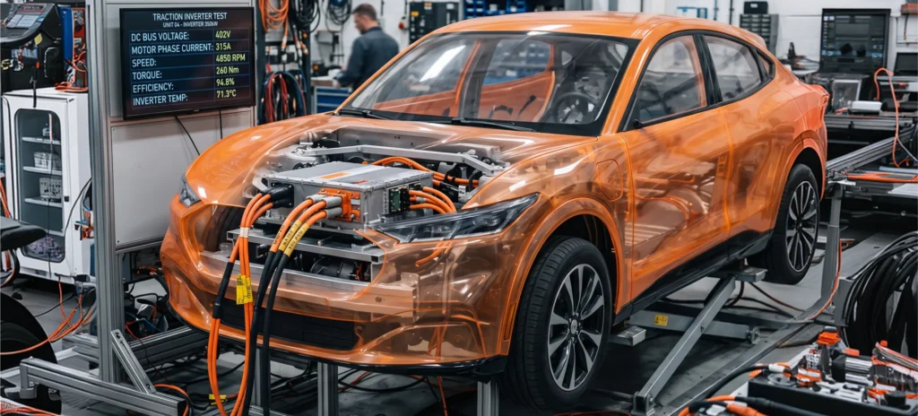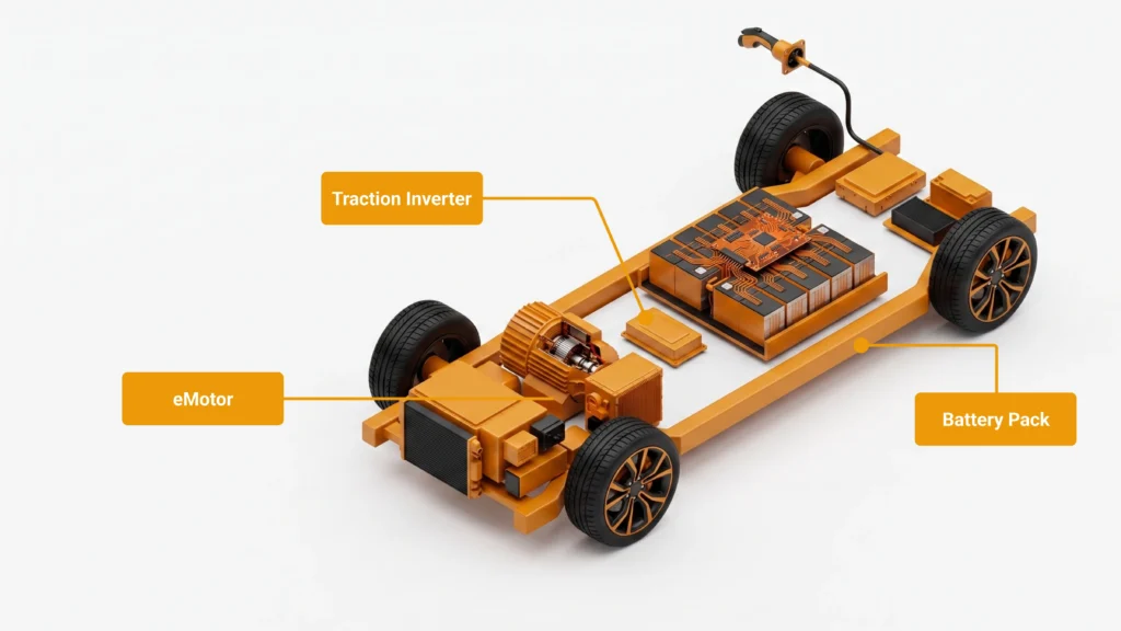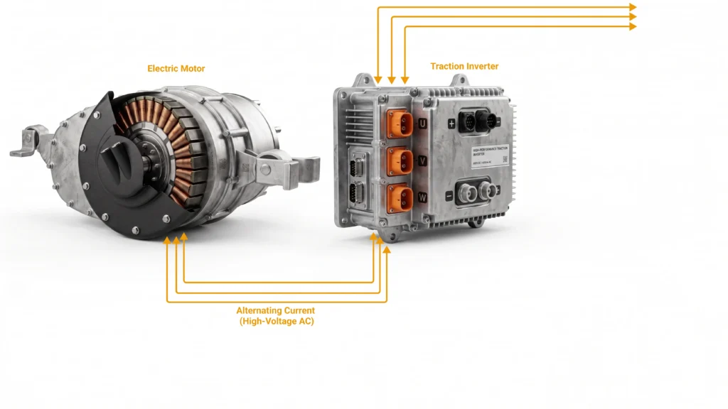

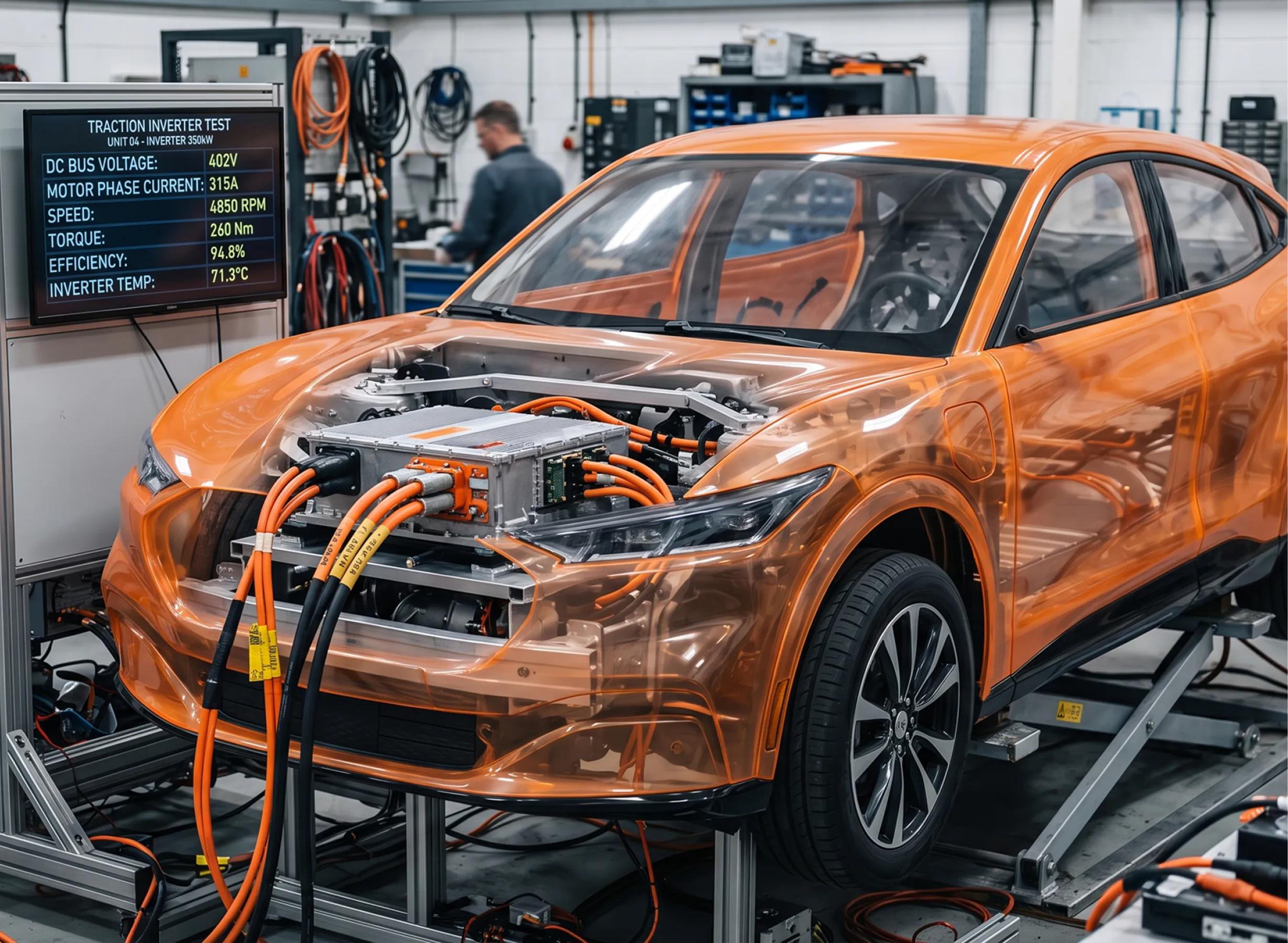
traction inverter test is the component that decides how far an electric vehicle goes, how smoothly it accelerates, and how safely it behaves when something breaks. It converts DC energy from the high-voltage battery into the precisely timed three-phase AC that drives the electric machine — and it does so while switching hundreds of amps at up to 800 volts, thousands of times per second. A traction inverter test program exists to prove that this power-conversion, control, and protection chain does what it is supposed to do across every operating point and every fault the vehicle will ever see. This guide walks validation and R&D engineers through the full scope of traction inverter testing, from control code to full power, and shows where a modern Hardware-in-the-Loop (HIL) and Power-Hardware-in-the-Loop (PHIL) platform changes the economics of the work.
The stakes are rising with the market. Mordor Intelligence values the traction inverter market at USD 11.12 billion in 2025 and projects it to grow at a 17.34% CAGR to USD 24.74 billion by 2030, driven by EV adoption, the industry-wide shift to 800 V architectures, and the transition from silicon IGBTs to wide-bandgap silicon carbide (SiC) and gallium nitride (GaN) devices. That transition is well underway but not complete: the same analysis notes IGBTs still held a 56.18% share in 2024, while SiC modules are growing at a 17.85% CAGR as wafer prices retreat. Those wide-bandgap devices switch faster and run hotter and higher, which improves efficiency and range but makes measurement, control, inverter test, and validation dramatically harder. Understanding inverter and motor technology in electric vehicles — the power stage, the gate drivers, the DC-link, the control unit, and the sensing that closes the loop — is the foundation of any credible EV traction inverter testing effort.
A traction inverter test is a structured verification of three things at once: the power electronics that convert and switch energy, the embedded control that commands them, and the protection logic that keeps the system safe when a fault occurs. Because those three domains interact, no single instrument or bench can cover them. The testing “system” is really a progression of environments, each adding realism: desktop simulation, signal-level HIL against the real controller, power-level PHIL with real current flowing, and finally mechanical dynamometer and in-vehicle testing.
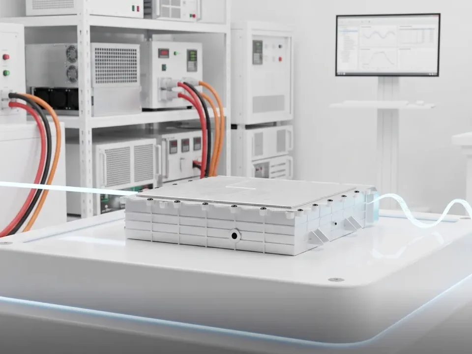
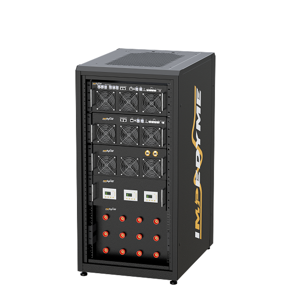
The heart of a modern electric vehicle inverter testing system is a real-time simulator that runs high-fidelity models of the motor and battery and exchanges signals — or real power — with the inverter under test in a closed loop. On an FPGA-based platform such as Die CHP-Serie von Impedyme, those models update at nanosecond-scale time steps, fast enough to resolve the switching behavior of SiC devices. Around that core sit the measurement instruments (oscilloscopes, precision power analyzers, impedance analyzers), the power interface (a regenerative amplifier that can source and sink energy), sensor and bus emulation, and an automation layer that turns a test plan into a repeatable, pass/fail campaign. The rest of this guide describes each of these layers and what each one proves.
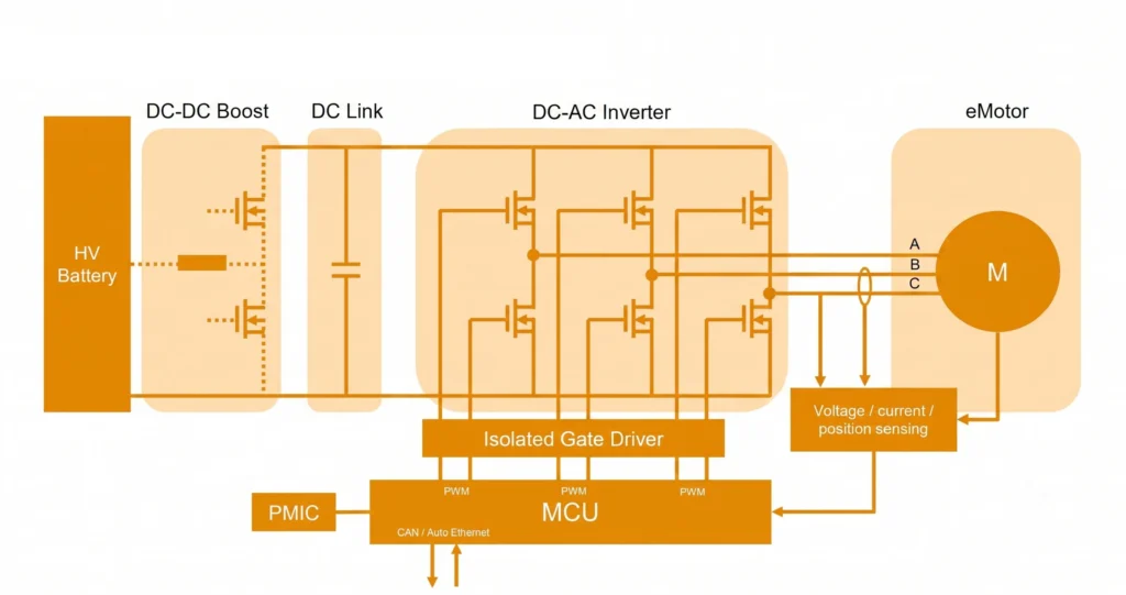
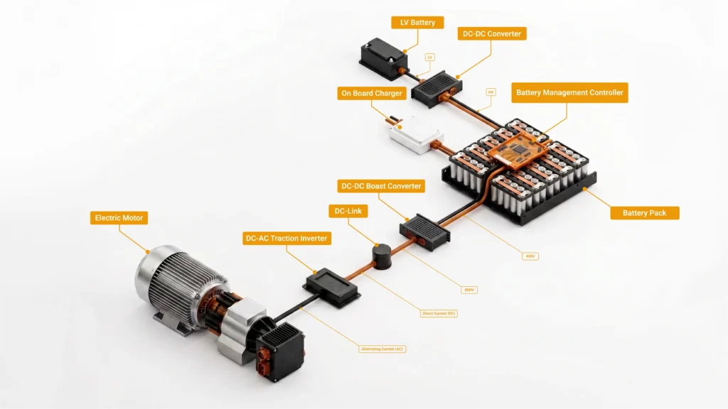
To understand what has to be tested, start with the power path. The accompanying traction inverter test schematic traces energy from the battery to the wheels and control from the microcontroller to the switches.
HV Battery. Everything begins at the high-voltage pack — typically a 400 V or 800 V DC source. In a test environment, this is exactly where a real-time battery emulator replaces the physical pack, so the inverter sees a programmable, safe, repeatable DC source whose voltage can be swept, sagged, or faulted on command.
DC-DC boost stage. Some drivetrains place a boost converter between the battery and the inverter to raise and stabilize the DC-link voltage. Its switching devices are a test concern in their own right: they must be characterized for switching loss and thermal behavior, and their control must be validated against input voltage transients.
DC-link capacitor. Between the boost stage and the inverter sits the DC-link capacitor, which buffers ripple current and stabilizes the bus during fast switching. Its parasitics — equivalent series resistance (ESR) and equivalent series inductance (ESL) — directly affect voltage overshoot, losses, and heat. A capacitor with too much ESL lets the bus ring and stresses the switches; too much ESR wastes energy as heat in a cramped, hot enclosure. This is why DC-link ESR/ESL measurement is a dedicated part of any bench characterization plan.
DC-AC inverter. The core is a three-phase, two-level bridge: three half-bridges, six power switches (IGBTs or SiC MOSFETs), each with an anti-parallel diode. Turning these switches on and off in the right sequence synthesizes three sinusoidal currents 120 degrees apart. Everything about how these switches turn on and off — timing, deadtime, edge rate, overshoot — determines efficiency, torque quality, EMI, and reliability.
Isolated gate driver. Below the power stage, an isolated gate driver receives low-voltage PWM commands from the microcontroller and translates them into the high-current, galvanically isolated gate signals that switch the power devices. The gate driver is also the first line of protection: it typically includes desaturation detection, undervoltage lockout, and active fault handling. Its behavior is safety-critical, and verifying it is central to a traction inverter test. Recent gate drivers add dynamic gate strength — the ability to vary the switching rate in response to conditions such as cold temperature or a raised bus voltage during regenerative braking — which improves efficiency and protection but adds another dimension that must be verified in test.
MCU and control. The microcontroller runs the control algorithm — usually field-oriented control (FOC) — generating the PWM patterns, managing field-weakening, and executing the safety state machine. It is connected to a power-management IC (PMIC) for its supply rails and to CAN and Automotive Ethernet for vehicle communication. In signal-level testing, this MCU (with its real firmware) is the device under test.
Voltage/current/position sensing. A sensing block feeds phase currents, DC-link voltage, and rotor position back to the MCU. The control loop is only as good as this feedback. In HIL testing, these sensor signals — including resolver or encoder position — are emulated by the real-time platform so the controller believes it is driving a real machine.
eMotor. Finally, the three phases (A, B, C) drive the motor M. In the physical world this is a PMSM, induction machine, or externally excited synchronous machine. In a PHIL environment, a motor emulator stands in for this machine as a real electrical load — the single most important substitution in modern ev inverter testing.
Every block above is both a function and a failure mode. The schematic is, in effect, a map of the test plan.
Strip away the instrumentation and a traction inverter test exists to demonstrate five things:
The device under test is a tightly integrated assembly: the power stage (six switches, often in a power module), the gate drivers, the DC-link capacitor, the control unit, the position sensing, and the cooling system. A credible test program exercises all of them together, because their interactions — not their individual specs — are what fail in the field.
The rest of this article is organized around how each of these is proven.
The bench-characterization side of a traction inverter test groups into a few well-defined solution categories, each mapping to an instrument class and a measurement question. The accompanying traction inverter test solutions diagram organizes these into three areas — the DC-AC inverter itself, the power modules, and the DC-link capacitor — supported by a power supply, an oscilloscope, a double-pulse tester, and an impedance analyzer.
Switching analysis. A high-bandwidth oscilloscope with matched high-voltage differential probes and current probes captures the turn-on and turn-off transients of each switch. Engineers extract switching loss, voltage overshoot, dv/dt and di/dt, and ringing. With SiC and GaN edges measured in tens of nanoseconds, probe bandwidth, deskew between voltage and current channels, and common-mode rejection at high dv/dt become decisive — small timing misalignments produce large apparent-power errors.
PWM signal analysis. The same class of instrument, with three-phase inverter/motor analysis software, displays the PWM drive signals alongside phase voltages and currents and derived phasor diagrams. This verifies modulation strategy, deadtime insertion, and phase balance, and it exposes control-logic problems that only appear as waveform artifacts.
Stability verification. Beyond steady state, the inverter must remain stable through transients — load steps, field-weakening entry, and DC-bus disturbances. This is where closed-loop HIL and PHIL testing add value that a bench scope alone cannot: they let you drive the controller through dynamic operating-point changes and observe whether the control loop holds.
Power-module device characterization (double-pulse testing). The double-pulse test (DPT) is the standard method for measuring the dynamic switching behavior of a power device or module. A first pulse ramps current in a load inductor to the target level; switching off captures turn-off behavior; a second pulse captures turn-on and diode reverse-recovery. From two pulses, engineers extract switching energies, overshoot, and reverse-recovery characteristics across voltage and temperature — essential for SiC, IGBT, and GaN devices. A double-pulse setup needs a stable DC source, a low-inductance load inductor, a controllable gate drive, and a wideband oscilloscope.
DC-link capacitor ESR/ESL measurement. An impedance analyzer sweeps the capacitor across frequency to extract ESR, ESL, and the self-resonant frequency at which the capacitor’s impedance is lowest. Because DC-link ESL is very small, this requires a low-inductance fixture and a compensation routine that removes fixture impedance from the result. The measured ESR and ESL feed directly back into predicting bus overshoot and loss in the switching analysis above.
Where these bench measurements characterize hardware in isolation, Impedyme’s HIL/PHIL platform closes the loop around the running system — sourcing the DC bus with a battery emulator, standing in for the machine with a Motoremulator, and capturing internal waveforms with FPGA Scope so that switching behavior, PWM patterns, and stability can be observed under realistic, repeatable, closed-loop conditions rather than static bench setups.
The single most important idea in modern traction inverter testing is that it is not one test but a staged progression up the V-cycle. Each stage catches a different class of defect, and each defect is cheaper to fix the earlier it is caught. Skipping stages is how expensive surprises reach the dynamometer or the vehicle.
Table 1. The stages of traction inverter testing.
| Stage | Real vs. Simulated | Purpose, Speed & Limitation |
|---|---|---|
| MIL | Real: Nothing (all models) Simulated: Controller + plant | Catches algorithm and control-law errors. Lowest cost and fastest iteration. Limitation: No production code or hardware. |
| SIL / PIL | Real: Production code (host/target) Simulated: Plant | Validates code generation, numerical behavior, and timing. Very low cost and fast. Limitation: No real I/O or power hardware. |
| Controller HIL | Real: ECU + firmware Simulated: Motor, inverter, battery, sensors | Detects deadtime issues, field-weakening behavior, ASC logic, and fault reaction timing. Low cost, fast, and repeatable. Limitation: No real power transfer. |
| Power HIL | Real: Inverter power stage Simulated: Motor (electrical load), battery | Evaluates switching losses, thermal behavior, saturation, and full-power faults. Moderate cost, repeatable, and safe. Limitation: Does not provide final mechanical validation. |
| Dyno / Vehicle | Real: Complete system Simulated: Little or nothing | Reveals mechanical, NVH, and system integration issues. Highest cost and slowest iteration. Limitation: Hazardous and difficult to repeat. |
| EOL | Real: Production unit Simulated: Emulated loads and sources | Detects manufacturing defects. Very fast per-unit testing. Limitation: Test coverage is constrained by production cycle time. |
Across these stages of traction inverter testing, the measurement categories — oscilloscopes, power supplies and electronic loads, precision power analyzers, and impedance analyzers — answer different questions, and measurement integrity is where results are won or lost. The most demanding measurement is efficiency, because it forces you to confront the high-frequency content of the inverter’s output.
An inverter’s output power is not a single clean tone. Its spectrum contains the fundamental (the frequency that actually produces torque), the low-order harmonics of that fundamental, and the carrier/switching frequency and its harmonics generated by the PWM. Only the fundamental drives the motor; virtually everything at higher frequencies is loss — dissipated as heat, acoustic noise, and vibration in both the inverter and the motor’s iron. As designs move to SiC and GaN and push switching frequencies up, this high-frequency loss becomes the battleground for the last fractions of a percent of efficiency, and it must be measured, not estimated.
Measuring it is genuinely hard. At the switching frequency and its harmonics, voltage and current are far out of phase, so the power factor is very low — and at low power factor, even a tiny phase error between the voltage and current channels produces a large error in the calculated power. This is why serious inverter power measurement depends on precise phase alignment (current-sensor phase compensation), very high common-mode rejection (the line-voltage measurement sees large common-mode swings at the switching edges), wide bandwidth and high sample rate, and tight synchronization across channels. The relevant power-analyzer parameters an engineer must weigh are therefore bandwidth, sample rate, amplitude accuracy/uncertainty, phase accuracy, common-mode rejection, and multi-channel synchronization.
Conceptually, this is why the most capable analyzers separate the fundamental power from the switching/high-frequency power rather than reporting a single lumped number. A dual-path style of analysis handles the low-frequency region (fundamental and harmonics) with one method and the high-frequency carrier region with a frequency-domain (FFT-of-power) method, so the engineer can attribute loss to the right physical mechanism — conduction versus switching, motor copper versus iron. Separating the spectrum this way tells you whether raising the carrier frequency (which lowers current ripple and motor harmonic iron loss) is worth the added switching loss in the inverter — the central efficiency trade-off in drivetrain tuning. The key point for a test plan is that a single efficiency number hides the physics; resolving the spectrum reveals it.
Controller HIL is the stage of ev traction inverter testing where the most defects are caught for the least money, because it exercises the real controller and its real firmware before any power hardware is committed. The controller sends PWM commands to what it believes is a real inverter and receives back phase currents, DC-link voltage, and rotor position exactly as a physical system would produce them — but all at the signal level, with no real power flowing.
The fidelity ceiling of controller HIL is set by how fast the plant model updates. A modern SiC inverter switches so fast that a conventional fixed-step CPU model, updating on the order of microseconds, simply cannot resolve individual switching events or capture PWM edges at the resolution the controller actually acts on. This is why FPGA-based real-time simulation matters: models running on an FPGA update at nanosecond-scale time steps and can capture gate signals at the resolution modern drivetrains demand. Impedyme’s platform runs motor and inverter models on FPGA with model steps as low as 90 nanoseconds, capturing PWM at nanosecond resolution, emulating ADC inputs, resolver/encoder position, and interfacing CAN and Automotive Ethernet — while reading back the controller’s gate signals in real time.
Because every one of these can be scripted and repeated exactly, controller HIL turns safety and control validation in electric vehicle inverter testing into a regression suite that runs on every firmware commit — something no dynamometer can offer.
Controller HIL proves the control logic. It cannot prove the power stage. That requires Power HIL (PHIL), and specifically motor emulation — the money stage of a traction inverter test, and the part most competitors skip or reduce to a spec sheet.
A motor emulator replaces the physical machine and dynamometer with a high-bandwidth, regenerative power converter that behaves electrically exactly like the motor. It draws and returns real current at the inverter’s phase terminals, reproducing the machine’s back-EMF, inductance, harmonic content, magnetic saturation, and cross-coupling between axes — in all four quadrants, motoring and generating. On the DC side, a battery emulator sources and sinks the bus current, so the inverter is tested inside the full electrical system it will actually live in, not against a passive R-L load that only ever absorbs reactive power and can never return energy to the DC link.
This matters because a passive load cannot stress the inverter the way a real machine does. Only an active emulator applies realistic active power, exercises the diodes and switches under true load, and reproduces regenerative power flow — exposing vulnerabilities that inductive test setups leave undetected.
Addressing the honest objections. PHIL is not free of difficulty, and a credible vendor says so. Because a real power converter now sits inside a closed control loop, loop delay, interface bandwidth, and the impedance interaction between emulator and inverter can threaten stability and accuracy if handled naively. The mitigations are a well-chosen interface algorithm, a high-bandwidth power stage co-designed with the real-time simulator to minimize latency, and careful impedance management — plus hardware safety interlocks, isolation, and protective trips sized for full fault energy. Impedyme’s CHP Series was built around exactly this integration: an FPGA real-time engine and a regenerative power interface with deterministic, ultra-low latency, so the motor emulation is both stable and faithful.
Motor emulation vs. the dynamometer. Against a mechanical dyno, motor emulation wins decisively on cost, throughput, repeatability, and fault safety. There is no mechanical coupling to spin up, no real motor to protect, and a fault can be injected and repeated identically thousands of times with zero risk to hardware or people. Extreme conditions — overspeed, phase short, cold-restart — that would destroy a real machine are simply data points. Where the dyno still wins: final mechanical validation, NVH, bearing and rotor-dynamic behavior, cooling-system integration under real mechanical load, and the last homologation confidence step. The honest position is that motor emulation absorbs the overwhelming majority of test iterations and lets the dyno be reserved for confirmation, not discovery.
If motor emulation is the money stage, fault injection is the differentiator competitors rarely address with real depth. A traction inverter is an ASIL-D item under ISO 26262 — its failures can cause life-threatening harm — and the standard does not just ask whether faults are detected; it asks whether the system reaches a safe state within a bounded time. That time can only be measured by injecting the fault and clocking the reaction, which is precisely what a HIL/PHIL platform does safely and repeatably.
A thorough fault-injection matrix includes: open-phase and short-phase faults; phase-to-phase short; DC-link undervoltage and loss of bus; gate-driver desaturation events; position-sensor loss and drift; overtemperature and thermal derating; HVIL (high-voltage interlock loop) break; and verification of the two safe states — active discharge of the DC-link and active short-circuit (ASC).
ASC deserves special attention because it is a genuine safety mechanism, not just a fault to detect. When an EV coasts or brakes at speed with the switches off, the spinning machine generates back-EMF and uncontrolled regenerative braking torque. To suppress this, the inverter turns on all three high-side or all three low-side switches to short the motor windings — clamping the phase voltages and eliminating the hazard. Verifying that this logic triggers correctly, on the correct switch bank, and within the required time is a core safety test. Active discharge is the complementary safe state: after a crash or HV disconnect, the DC-link capacitor must be bled down to a safe voltage. Under UN ECE Regulation No. 94, that safe voltage is defined as 60 V, and the DC bus has to reach it in less than 5 seconds after a crash — the window in which first responders and service staff must not be exposed to a lethal charge. (Individual OEM and standard requirements vary; some active-discharge specifications call for reaching the safe level within about 2 seconds.)
These reactions span very different time scales. Gate-driver-level short-circuit and desaturation reactions are expected to complete in a few microseconds — an ISO 26262 ASIL-C/D-rated gate driver, for example, can react to a short circuit in under 2 microseconds for IGBTs and faster for SiC. System-level torque-related safety goals, by contrast, carry a longer fault-tolerant time interval: over-torque and over-braking hazards are classified as ASIL-D with an FTTI goal on the order of 200 milliseconds — the maximum time to transition to a safe state. A HIL platform can measure both regimes — the microsecond gate reaction and the millisecond system reaction — against the safety requirement, producing the timed evidence a safety case needs. This is the strongest topical ground a traction inverter test program can own, and it is where an integrated simulation-plus-power platform is not merely convenient but necessary.
Standards do not just gate release; they dictate what you must be able to test. The table below summarizes the ones that most shape a traction inverter test plan.
Table 2. Standards that shape the traction inverter test plan.
| Standard | Governs | What it forces you to test |
|---|---|---|
| ISO 26262 | Functional safety of automotive E/E systems (ASIL A–D) | Fault detection and safe-state reaction within bounded time; the inverter is treated as ASIL-D |
| ISO 21498 / LV 123 | HV (voltage class B, 60–1500 V DC) electrical specs and behavior | Behavior across HV sub-classes (e.g., 400 V/800 V), voltage tolerance, discharge behavior |
| LV 124 / LV 148 | Low-voltage electrical requirements (incl. 48 V board net) | Low-voltage supply behavior, transients, and 48 V board-net interactions |
| ISO 16750 | Environmental and electrical loads on road-vehicle components | Temperature, vibration, and electrical-environment robustness |
| CISPR 25 | Conducted and radiated emissions from vehicle components (limit classes 1–5) | Emissions limits, typically to Class 5; the 2021 edition covers 150 kHz to 5925 MHz |
| ISO 11452 | Component immunity to radiated/conducted disturbance | Immunity via bulk current injection, TEM/strip-line, and radiated-field methods |
| UN ECE R100 | EV safety and rechargeable energy-storage systems (REESS) | HV safety, isolation, and battery-system integrity requirements |
| SAE J2907 | Motor-inverter (electric drive subsystem) performance characterization | Repeatable out-of-vehicle power/torque rating, including maximum 30-minute power |
| AEC-Q100 | Component-level qualification of automotive ICs | Device-level stress qualification for the ICs used in the inverter |
The practical takeaway: functional safety (ISO 26262) drives fault injection and timing measurement; the HV and low-voltage standards (ISO 21498/LV 123, LV 124/LV 148) drive supply and discharge testing; ISO 16750 drives environmental robustness; CISPR 25 and ISO 11452 drive EMC pre-compliance; UN ECE R100 covers the energy-storage safety envelope; SAE J2907 defines how performance is rated (structured similarly to UN ECE R85 for net and 30-minute power, with in-vehicle testing covered by SAE J2908); and AEC-Q100 governs the parts inside. A well-built bench lets you exercise most of these from a common set of models.
Specifying a traction inverter test bench is an exercise in matching capability to the defects you need to catch. The checklist below captures the decisions that matter.
Table 3. Bench capability checklist.
| Anforderung | Why it matters | What to specify |
|---|---|---|
| Real-time platform | Sets the fidelity ceiling; CPU models cannot resolve SiC switching | FPGA-based execution, nanosecond-scale model steps, low I/O latency |
| Power interface rating and bandwidth | Determines what power-stage behavior you can reproduce | Voltage/current rating, four-quadrant regenerative capability, amplifier bandwidth beyond control/plant frequencies |
| Battery / DC emulation | The inverter must see a realistic, faultable DC source | Programmable voltage, current sink/source, fast transients, fault injection |
| Sensor-Emulation: | The controller only trusts its feedback | Resolver/encoder emulation, ADC-level current/voltage signals, configurable faults |
| Bus interfaces | The controller lives on the vehicle network | CAN, CAN FD, Automotive Ethernet, with trigger/decode |
| Automation and sequencing | Coverage and repeatability depend on it | Scripted campaigns, pass/fail criteria, CI integration, requirements traceability |
| Safety architecture | Full fault energy is present in PHIL | Isolation, interlocks, protective trips, crowbars, thermal monitoring |
| Scalability 400 V → 800 V | Programs span voltage classes and power levels | Paralleling/scaling path, headroom for higher voltage and current |
The guiding principle: prove control and protection at signal-level HIL, use PHIL for full-power and fault coverage, and reserve the dynamometer for final mechanical validation. That sequence minimizes amplifier hours, wiring cycles, and risk.
The same models and much of the same bench follow the inverter across its life — only the rigor changes. In R&D, models and controller HIL let engineers iterate control and protection before hardware exists. In Validierung, PHIL with motor and battery emulation sweeps the full envelope and runs the fault matrix against safety requirements. In pre-production, the bench confirms production-representative hardware against the full standards set. At end-of-line, a fast automated subset of the same checks verifies every unit shipped. Reusing models and test cases across these phases is what keeps a program coherent — a defect definition written in R&D can still be the pass/fail gate on the production line.
Active motor emulation represents a significant advancement in PHIL validation, replacing physical rotating machines and mechanical dynamometers with a fully software-defined, high-power electronic simulator.
In an active motor emulation system, the physical motor and dynamometer are replaced by a high-bandwidth, bidirectional electronic converter. The traction inverter’s AC phases are connected directly to this electronic converter.
The emulator measures the instantaneous terminal voltages generated by the inverter and feeds these values into a high-fidelity Permanent Magnet Synchronous Motor (PMSM) or induction machine model running on the real-time FPGA.
The model calculates the exact currents that a physical motor would produce under those voltage conditions and commands the electronic power stage to force those currents back into the inverter’s AC terminals. This execution loop operates with a ninety-nanosecond model update rate and can handle power levels up to a one-thousand-volt DC-link and eight-hundred amperes RMS, providing true real-time power transfer.
Active motor emulation offers major advantages over physical mechanical test benches :
Impedyme was built to own the whole progression that this guide describes — from control code to full power — on a single, integrated platform rather than a patchwork of instruments and one-off rigs.
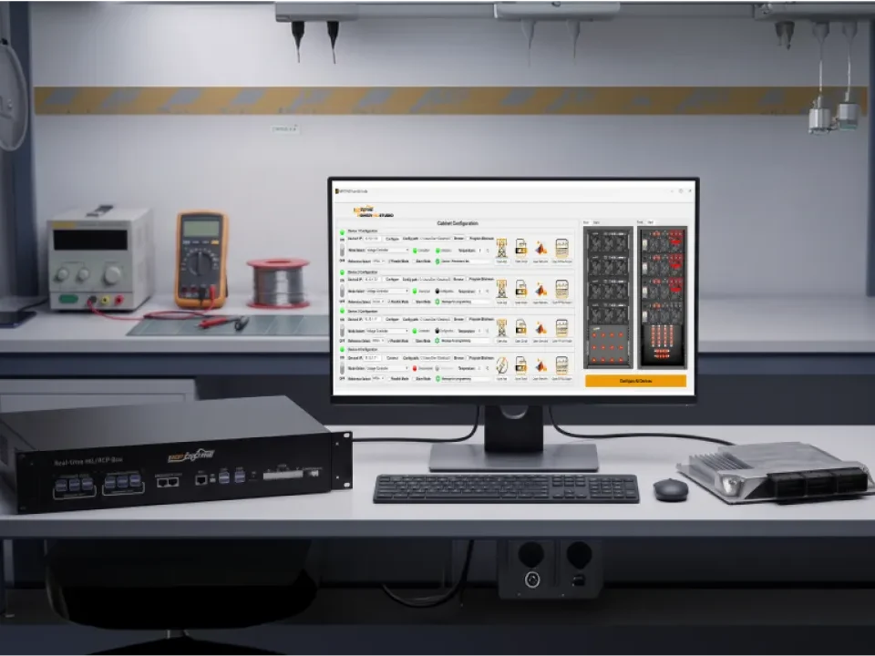
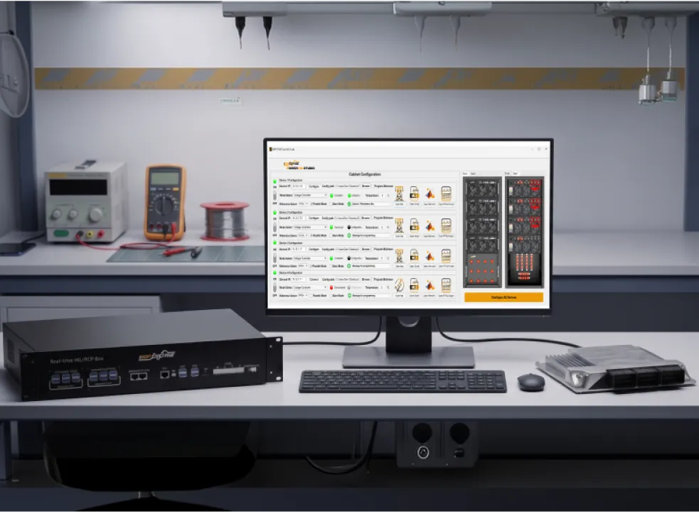
Supporting tools round out the platform: FPGA Scope captures internal waveforms at model resolution, the HIL/RCP-Box enables signal-level motor emulation for early controller work, and Impedyme-RT . connects model-based design tools directly to the hardware with automatic code generation. The result is a platform that catches the cheapest defects first at signal level, proves the power stage safely under motor emulation, measures functional-safety fault-reaction times as timed evidence, and reserves the dynamometer for confirmation — covering the parts of ev traction inverter testing that instrument-only and spec-sheet approaches leave open.
A traction inverter test is not a single measurement or a single bench — it is a coverage problem that spans control code, full power, and every fault the vehicle will ever face. The programs that succeed treat traction inverter testing as a staged progression: prove the control and protection logic at signal-level HIL, prove the power stage safely under motor emulation, capture functional-safety fault-reaction times as timed evidence, and reserve the dynamometer for final mechanical confirmation. That sequence catches the cheapest defects first, turns validation into a repeatable regression suite, and keeps the same models flowing from R&D to end-of-line. As drivetrains push to 800 volts and wide-bandgap devices, the parts most competitors skip — motor emulation, fault injection, and ISO 26262 safe-state verification — are exactly where an integrated FPGA-based platform earns its place, and exactly where Impedyme’s CHP Series, PowerHIL Studio, MotorSim Studio, and Real-Time Battery Emulator turn a demanding electric vehicle inverter testing program into a fast, safe, and fully traceable one.
Why is HIL testing used for traction inverter testing?
HIL exercises the real controller and firmware against a real-time model before any power hardware is committed, catching the cheapest defects first. On an FPGA platform, models resolve modern SiC switching, so control, protection, and fault reactions can be validated and repeated exactly on every firmware revision.
What is motor emulation in EV traction inverter testing?
It’s a regenerative power converter that replaces the physical machine and dynamometer, behaving electrically like the motor — sourcing and sinking real current while reproducing back-EMF, inductance, saturation, and harmonics in all four quadrants. This validates a physical inverter at full power without a real motor.
How is inverter efficiency measured, and why is high-frequency power hard to capture?
Efficiency is measured with a precision power analyzer across synchronized voltage and current channels. It’s hard because switching-frequency content sits at very low power factor, where a tiny channel phase error causes a large power error — demanding phase compensation, high common-mode rejection, wide bandwidth, and tight synchronization.
What is a double-pulse test?
It’s the standard method for characterizing a power device’s dynamic switching. A first pulse ramps current in a load inductor to capture turn-off, and a second pulse captures turn-on and reverse-recovery — yielding switching energies, overshoot, and reverse-recovery across voltage and temperature for SiC, IGBT, and GaN devices.
Why does ISO 26262 matter for a traction inverter test?
A traction inverter is an ASIL-D item — the highest safety level — because its failures can cause serious harm. The standard requires faults to be detected and a safe state reached within a bounded time, which can only be verified by injecting faults and measuring the response.