
The rapid global transition toward the decarbonization of transport networks and electric power grids has accelerated the demand for high-capacity, high-performance energy storage systems. Embedded controllers must be developed and tested to govern electric powertrains and their components, particularly the systems designed for managing and controlling batteries.
As technology advances, battery packs are undergoing a major evolution. Manufacturers are continuously adopting new chemistries—such as advanced lithium-ion, lithium iron phosphate, nickel manganese cobalt, nickel cobalt aluminum, and solid-state variants—to achieve higher energy densities, superior thermal performance, and improved cost-effectiveness. Consequently, contemporary battery packs must deliver significantly more electrical capacity while utilizing less physical space, all while maintaining rigorous safety standards.
To decrease electrical conduction losses and improve overall powertrain efficiency, a prominent trend has emerged to increase battery system operating voltages. Standard passenger electric vehicles are transitioning from traditional 400 V architectures to advanced 800 V configurations, while heavy-duty industrial, military, maritime, and utility-scale stationary energy storage systems are pushing voltage thresholds up to 1500 V.
Operating at these elevated voltage levels requires a highly sophisticated control framework. High-voltage battery systems require specialized controllers, commonly referred to as Battery Management Systems (BMS), to maintain performance, safety, and longevity.
Because the BMS acts as the primary brain of the energy storage system, testing these controllers must be fast, safe, and repeatable. Ideally, this validation should be conducted without requiring physical battery hardware, which is where hardware-in-the-loop (HIL) testing of battery management systems becomes an indispensable methodology in modern engineering workflows.
The pressure on battery management systems has never been higher. Decarbonization is pushing electric vehicles, stationary storage, and electrified aircraft into the mainstream. The global EV battery market was valued at roughly USD 77 billion in 2025 and is projected to keep climbing steeply through the next decade (estimates vary by analyst, but every credible forecast points sharply upward). Every one of those packs needs a BMS, and every BMS needs validation.
Three trends are making that validation dramatically harder:
Against that backdrop, “hardware in the loop testing of battery management systems” is no longer a nice-to-have late in the program. It is the core discipline that determines whether a battery product is safe, certifiable, and on schedule.
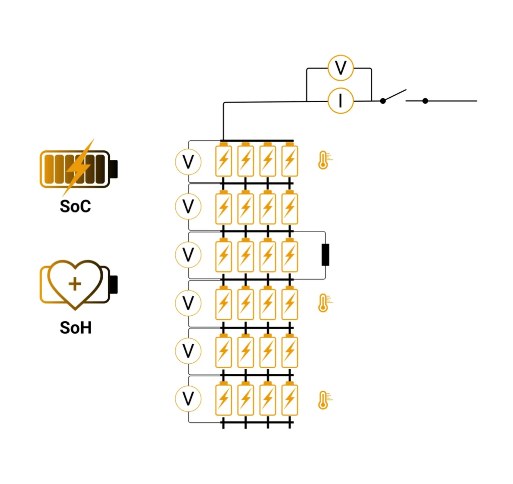
To understand why HIL testing of BMS is so demanding, you have to understand how much the BMS is responsible for. In a high-voltage traction battery, individual lithium-ion cells of roughly 3.6 to 3.7 V are connected in long series strings to reach 400 V, 800 V, or more. A 400 V-class pack typically uses around 96 cells in series; 800 V architectures stack more than 200. Every one of those cells must be monitored to within a few millivolts while floating at hundreds of volts.
The BMS handles:
Because these functions interact — an SOC error can trigger a false fault, a missed measurement can corrupt balancing — the BMS must be tested as an integrated system across its entire operating and fault envelope. That is precisely the combinatorial problem HIL testing was built to solve. A widely referenced paper presented at a 2013 automotive-control symposium on HIL testing of battery management systems framed the core requirement cleanly: testing a BMS on a HIL bench requires “an electronics unit to simulate the cell voltages and a scalable real-time battery model,” combined into a modular, safety-conscious system.
Validating these safety-critical control algorithms against physical battery packs in a laboratory environment presents significant safety, economic, and operational challenges.
Lithium-ion chemistries store high chemical energy and are susceptible to catastrophic failures if operated outside their strict thermal and electrical envelopes. Testing a BMS against real battery packs to validate its safety limits—such as injecting short circuits, forcing overcharge conditions, or simulating cooling system failures—poses immediate risks of fire, toxic gas emissions, and explosive thermal runaway.
Staging these extreme scenarios requires explosion-proof test chambers, specialized chemical fire suppression systems, and extensive safety protocols, making physical destructive testing highly dangerous and difficult to execute on a routine basis.
Characterizing cell behavior over its complete operating lifetime requires thousands of charge and discharge cycles. In a physical laboratory setting, executing these aging tests requires weeks, months, or even years of continuous cycler operation.
Furthermore, physical cells cannot be easily reset to a specific state. If a test case requires a precise starting cell voltage imbalance (e.g., cell number eight resting at a specific high voltage while other cells remain low), the test operator must manually charge or discharge individual cells to achieve the exact scenario. This manual preparation is exceptionally slow, highly error-prone, and limits the throughput of testing programs.
The physical properties of lithium-ion cells change continuously as a function of temperature history, cycle count, calendar age, and chemical degradation. A test executed on a physical pack today will yield different thermal and voltage characteristics tomorrow.
This inherent variability makes it exceptionally difficult to reproduce specific diagnostic or algorithmic behaviors with the precision required to debug complex embedded firmware. Without a deterministic, repeatable test stimulus, validating the regression performance of BMS algorithms remains a major engineering challenge.
Between offline, desktop simulation of a battery model and full physical testing with real packs lies a chasm engineers call the validation gap. Offline models are safe and fast but cannot exercise real BMS firmware against real electrical signals or real power. Physical testing is realistic but slow, dangerous, and impossible to run at scale. Bugs that slip through the gap surface late — on prototype hardware, in certification, or worst of all, in the field.
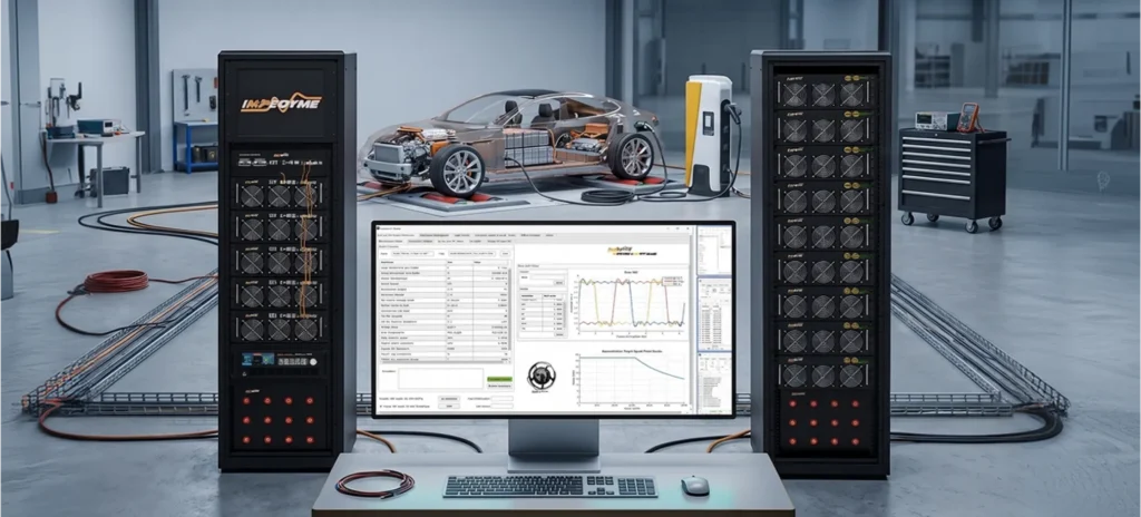
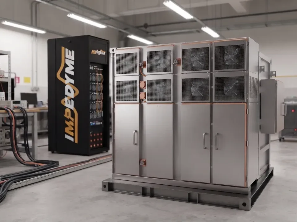
Impedyme was built to close that gap. The company builds FPGA-based Power Hardware-in-the-Loop systems and Combined HIL and Power (CHP) platforms, and its BatterySim Studio software turns that hardware into a complete battery emulation and testing environment. The battery model executes on Impedyme’s FPGA-based real-time hardware with model update rates as low as 90 nanoseconds, driving a fully regenerative power stage. The emulated battery connects directly to the real device under test — a BMS, traction inverter, on-board charger, DC fast charger, or DC-DC converter — all at production voltage and current. This is the bridge: engineers validate their BMS with Impedyme hardware and software against emulated cells that behave indistinguishably from real ones, long before real packs enter the picture.
At the heart of HIL testing of BMS is a simple substitution: replace the battery with a programmable, bidirectional power system that electronically reproduces the battery’s terminal behavior — voltage as a function of SOC, internal resistance, dynamic polarization, power limits, and thermal coupling — with no physical cell present. When that emulator is driven by a high-fidelity real-time model and coupled to actual power hardware through a regenerative converter, the methodology is Power Hardware-in-the-Loop. The Impedyme Real-Time Battery Emulator delivers exactly this: a digital battery twin whose real voltages and power are controlled by models, adaptable to different chemistries and pack architectures.
Several emulation subsystems make it work.
The cell emulator reproduces individual cell terminal voltages dynamically. Because packs connect hundreds of cells in series, each emulator channel must be completely galvanically isolated from other channels and from the chassis. Impedyme’s approach provides isolated, high-accuracy per-cell voltage outputs with source-and-sink current capability for balancing tests, sufficient resolution and low ripple to capture microvolt-level balancing transitions, and step responses fast enough to reproduce genuine cell dynamics. Because BMS protection thresholds and SOC estimation hinge on tiny voltage differences near cutoff — especially for flat-OCV chemistries like LFP, where roughly a millivolt of drift shifts the SOC estimate — measurement and control fidelity is decisive. BatterySim Studio runs on hardware delivering 24-bit resolution and microsecond-level loop rates.
Battery packs rely on negative temperature coefficient (NTC) and positive temperature coefficient (PTC) thermistors distributed across the modules. The HIL rig emulates these with programmable, isolated resistance channels spanning the full thermistor range with fine adjustment resolution and fast settling, so the rig can reproduce localized heat generation, cooling-fan response, and thermal-runaway precursors.
Fault injection is the heart of BMS validation, because the BMS lives or dies on edge cases. A comprehensive HIL testing of BMS campaign injects and verifies detection and response to:
Because the faults are emulated, the BMS repeatedly executes its safety responses without any risk to real hardware — directly satisfying the fault-injection evidence that functional-safety standards demand. BatterySim Studio supports a large catalog of fault types across a full state-of-health range and a wide temperature envelope, re-running scripted fault catalogs and capturing pass/fail signatures on every test.
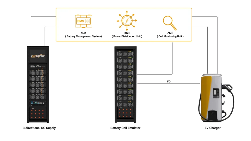
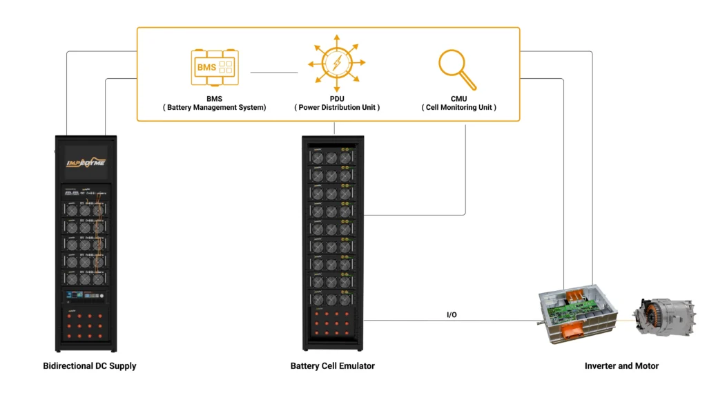
Real BMS validation extends beyond cell signals to the power distribution unit (PDU) and high-voltage path: isolated pack-voltage sensing at multiple points, shunt and Hall-effect current sensors, contactor and pre-charge control, isolation-resistance monitoring, high-voltage interlock loop signaling, and pyrofuse triggering. Testing these interactions realistically requires Power-HIL, because the emulated pack must deliver real current and voltage so contactors weld or release, pre-charge ramps behave correctly, and fast protective devices trigger under genuine electrical conditions. Impedyme’s regenerative CHP power stage makes this possible while recirculating energy rather than dissipating it.
| Parameter | Conventional Signal-Level HIL | Power Hardware-in-the-Loop (PHIL) | Physical Battery Pack Testing |
|---|---|---|---|
| System Voltage Boundary | Evaluated at signal interface level (e.g., 5 V) | Full high-voltage operation (e.g., up to 1500 V) | Real voltage limits of physical pack (e.g., up to 1500 V) |
| Current Limits | Low signal levels (milliamps) | Complete full-power flow (kilowatts to megawatts) | Extreme chemical power output |
| Physical Safety Risk | Zero hazard | Moderate (requires electrical safety containment) | Extremely high (chemical fire, explosion) |
| Developmental Velocity | Extremely high (fast automation, zero recharge wait) | High (rapid iteration with physical power hardware) | Slow (restricted by physical thermal and chemical constraints) |
| Coverage of Extreme Failures | Comprehensive (safely tests shorts, degradation, open pins) | High (covers electrical fault events at high power) | Extremely low (risks destroying cells and laboratory) |
| Dynamic Charger/Inverter Interaction | Purely simulated | Fully physical closed-loop at full voltage/current | Highly restrictive and slow to re-stage |
| Hardware Costs | Minimal to Moderate | Moderate to High (requires power converters) | High recurrent costs (spent cells, custom containment) |
A modern BMS is usually distributed across two tiers: cell-monitoring units (often several per pack) that use multi-channel analog front-end ICs to measure cell voltages and temperatures, and a master battery management controller that runs estimation, control, and protection logic and talks to the rest of the vehicle. The cell-monitoring units typically daisy-chain to the master over an isolated serial link, so cell data moves up long, high-voltage strings without ground loops. Alongside sits the power distribution unit that switches, protects, measures, and isolates the high-voltage path.
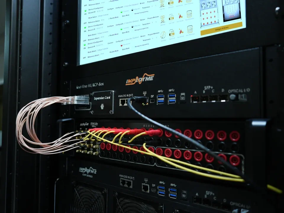
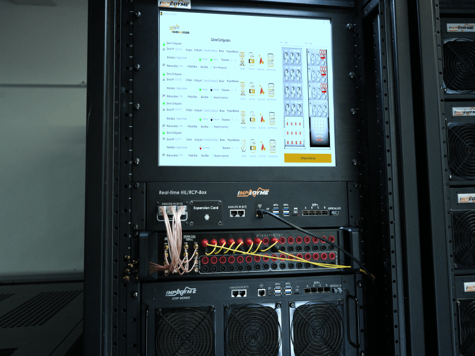
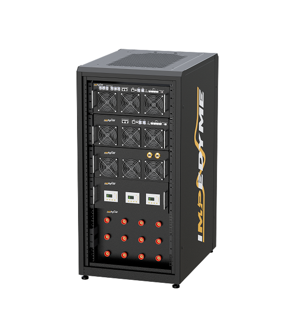
To validate the master controller and the cell-monitoring units together, the HIL rig must present all of these interfaces convincingly: isolated per-cell voltages that can be series-stacked to full pack voltage, temperature-sensor resistances, current-sensor signals, the isolated daisy-chain communication, the vehicle CAN/CAN FD network, and the high-voltage sensing and switching signals of the PDU. Impedyme’s platform delivers these as programmable emulation coordinated by PowerHIL Studio and exposed directly in a model-based design environment for real-time interaction and parameter tuning.
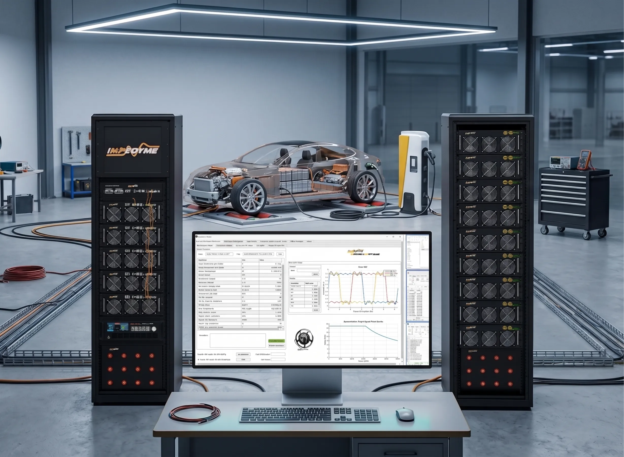
A production-grade BMS HIL testbed built on the Impedyme CHP Series integrates several coordinated subsystems:
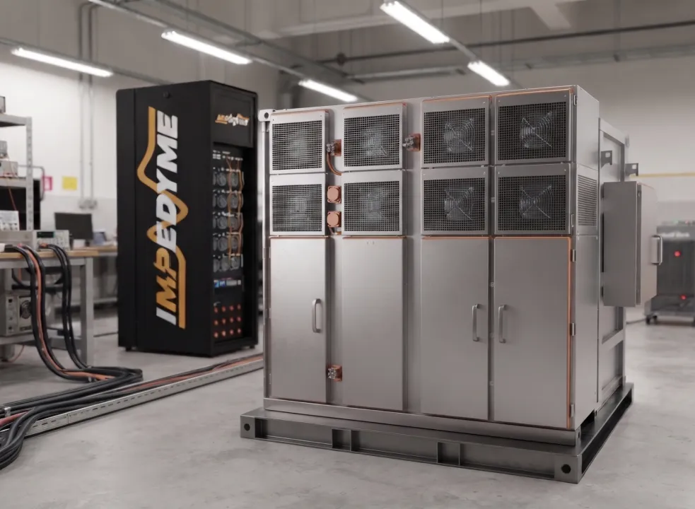
Impedyme’s Power HIL modules are built on embedded FPGA real-time processing units providing 16 analog input and 16 analog output channels at 5 MS/s and 16-bit resolution, 1 MHz waveform logging through the integrated FPGA Scope, and four optical ports per module for deterministic synchronization across units — so a testbed scales to hundreds of channels while maintaining nanosecond-level timing. A single CHP cabinet delivers substantial regenerative power, and units parallel for higher levels. The CHP-150 half-cabinet and CHP 300 full-cabinet configurations cover benchtop through rack-scale programs.
A useful balancing test begins with deliberate mismatch. Start a group of cells a few tens of millivolts apart, run a full charge/discharge cycle, log the balancing current per channel, then repeat after a calendar rest and another cycle. The questions: when does balancing start, how evenly does it act across channels, and how much drift returns after rest and load? Passive balancing can look fine at top-of-charge and still leave weak cells behind once load resumes. Emulated cells make this test perfectly repeatable and let engineers stage any imbalance pattern instantly.
To validate overcurrent protection, the rig injects current spikes through current-sensor emulation or, at power, commands the regenerative stage to drive genuine overcurrent, confirming the BMS interrupts within its required window and drives the pack to a safe state. External short-circuit, overcharge, over-discharge, and over-temperature scenarios follow the same logic — scripted, executed, and replayed with zero cells at risk.
Functional-safety practice ties every test to a documented requirement and maintains traceability from requirement to test case to result. HIL makes this practical: each safety goal maps to a scripted scenario with automated pass/fail criteria. PowerHIL Studio automates entire test sweeps through scripting — loops, conditional logic, automated logging, and report generation — so a suite covering hundreds of fault permutations runs overnight instead of consuming a quarter of physical lab time.
Because emulated tests are safe and repeatable, they slot directly into a continuous-integration pipeline. Every BMS firmware commit can trigger a regression run against the full fault catalog, with results logged automatically and flagged on failure. This 24/7, requirements-based testing is impossible with live batteries and is where emulation pays off most dramatically.
One of the strongest arguments for emulation-based HIL testing of BMS is that a single methodology scales across the entire product range. A compact benchtop setup might emulate a dozen cells for cell-monitoring-unit firmware work. A full rack scales to hundreds of cells in series — well past 250 — to represent 400 V and 800 V EV packs and 1500 V stationary strings, with series isolation into the kilovolt range. Impedyme’s platform scales from a benchtop cell to a megawatt traction pack within one architecture, because every power stage is regenerative and bidirectional and units synchronize over deterministic optical links. Teams move between chemistries and voltage classes without rebuilding their test infrastructure.
The fidelity of any HIL or PHIL test depends on how fast and how deterministically the battery model executes. Traditional CPU-based real-time simulators are typically limited to roughly 20 to 50 kHz update rates by I/O latency, and their timing suffers jitter from scheduling and interrupts. For battery emulation feeding fast protection and balancing loops — and especially for PHIL coupled to switching converters — that is often not fast or deterministic enough.
FPGAs change the game. Because an FPGA computes the model in massively parallel logic rather than sequential instructions, it achieves extremely small, fixed time steps with sub-microsecond, low-jitter I/O latency. The benefits for HIL testing of BMS:
Impedyme’s FPGA-based HIL integrates processing and I/O on the same chip, achieving simulation steps as fast as one microsecond, while BatterySim Studio runs its battery model on the CHP platform with steps as low as 90 nanoseconds, bandwidth up to 20 kHz, and high-speed optical links. That nanosecond-class execution is what lets a BMS interact with a virtual battery that behaves indistinguishably from the real thing.
A BMS in a road vehicle is a safety-critical item under ISO 26262, the automotive functional-safety standard, where voltage, temperature, and current measurement functions sit alongside airbag and braking systems in integrity terms. Top-level battery safety goals commonly map to the highest ASIL ratings, and the standard explicitly drives extensive fault-injection testing of overcharge, over-discharge, over-temperature, overcurrent, and short-circuit protection — the single strongest practical reason to adopt emulation-based testing.
Beyond ISO 26262, a BMS program intersects UN ECE R100 for electric road vehicles, UL 2580 for EV battery systems, IEC 61508 as the functional-safety foundation, and for stationary storage IEC 62619, UL 1973, UL 9540 and UL 9540A, and NFPA 855. Aerospace and eVTOL batteries add the highest reliability and availability requirements. Across all of them, the common thread is documented evidence across hundreds of operating and fault conditions — evidence that physical prototypes alone rarely deliver economically, and that automated HIL and PHIL produce as a byproduct of every run.
Impedyme-RT features deep integration with standard engineering toolchains, eliminating the need for complex, manual code conversions. Through native compatibility with MATLAB and Simulink, engineers can deploy Simulink battery and control models directly to real-time hardware.
Using MATLAB HDL Coder, Embedded Coder, and Workflow Advisor, users can move from high-level, FPGA-based algorithm design to high-bandwidth, full-power prototype validation within a single, integrated workflow. This eliminates proprietary toolchain bottlenecks and enables seamless model and test-asset reuse.
| Feature / Specification | Technical Value & Capability |
|---|---|
| Real-Time Execution Step Size | Down to 1 microsecond (µs) overall simulation loop; 90-nanosecond (ns) steps for FPGA-based battery plant models |
| Analog Input/Output Resolution | 24-bit high-resolution delta-sigma conversion interfaces |
| System Loop Rate | Microsecond-level (µs-level) deterministic feedback loop |
| High-Speed Optical Communication | 12.5 Gbps ultra-low latency multi-gigabit fiber link interconnects |
| HIL to Power-HIL Scalability | 50 kW stand-alone liquid-cooled cabinet, parallelable up to 550 kW/kVA |
| Electrochemical Impedance Spectroscopy (EIS) | Wideband frequency sweep (sub-Hz to 20 kHz) with micro-ohm accuracy under 1000 V+ operation |
| Fault Injection Capabilities | Over 50+ pre-configured electrical and thermal fault scenarios |
| Supported Battery Chemistries | Li-ion, LFP, NMC, NCA, Solid-State, and custom user-defined chemistries |
| MATLAB/Simulink Integration | Native deployment using .slx format, MATLAB HDL Coder, and Embedded Coder |
Hardware in the loop testing of battery management systems turns weeks of risky physical testing into automated, repeatable, fault-rich validation that produces the evidence regulators and OEMs demand. Impedyme brings the whole workflow into one workspace. BatterySim Studio unifies EIS measurement, automatic ECM fitting, real-time HIL and Power-HIL emulation, and live fault diagnostics in a model-based design environment, running on the FPGA-based CHP Series platform with nanosecond-class time steps and scaling from a benchtop cell to a megawatt traction pack. PowerHIL Studio orchestrates the campaigns; the Real-Time Battery Emulator provides the digital battery twin; FPGA Scope captures the waveforms; and Impedyme-RT carries reusable test assets from simulation to full hardware.
Whether you are validating an EV BMS to the highest ASIL level, characterizing a stationary storage rack, or qualifying an aerospace battery, Impedyme’s CHP-150 and CHP 300 hardware and software give your team the speed, fidelity, and safety to ship with confidence.
What is HIL testing of BMS?
Connecting a real BMS to an emulated battery — cell voltages, temperatures, currents, and communication generated by a real-time model — so the controller can be exercised across every operating and fault condition without a physical pack.
Why does FPGA-based execution matter?
FPGAs provide deterministic, sub-microsecond, low-jitter timing and time steps down to nanoseconds on the Impedyme CHP platform — so the emulated battery interacts stably with fast control loops and produces repeatable, certification-grade results.
What faults can be injected during HIL testing of BMS?
Overvoltage, undervoltage, overcurrent, overtemperature, cell imbalance, micro-shorts, sensor faults (open circuit, short, reverse polarity, drift), and communication faults such as dropped or corrupted CAN frames and bus-off.
How many cells can an Impedyme BMS HIL rig emulate?
From roughly a dozen cells on a benchtop setup to hundreds of cells in series in a full rack — past 250 — covering 400 V and 800 V EV packs and 1500 V stationary strings.
Which standards drive BMS HIL testing?
ISO 26262 and UN ECE R100 for road vehicles; UL 2580 for EV battery systems; IEC 61508 as the foundation; and IEC 62619, UL 1973, UL 9540/9540A, and NFPA 855 for stationary energy storage.