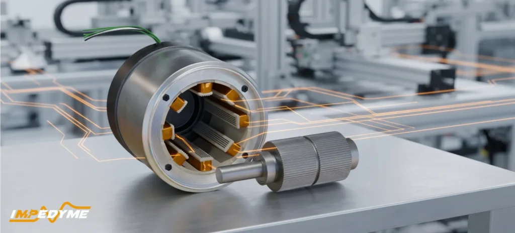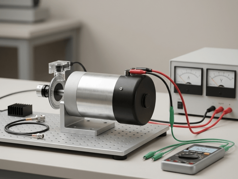

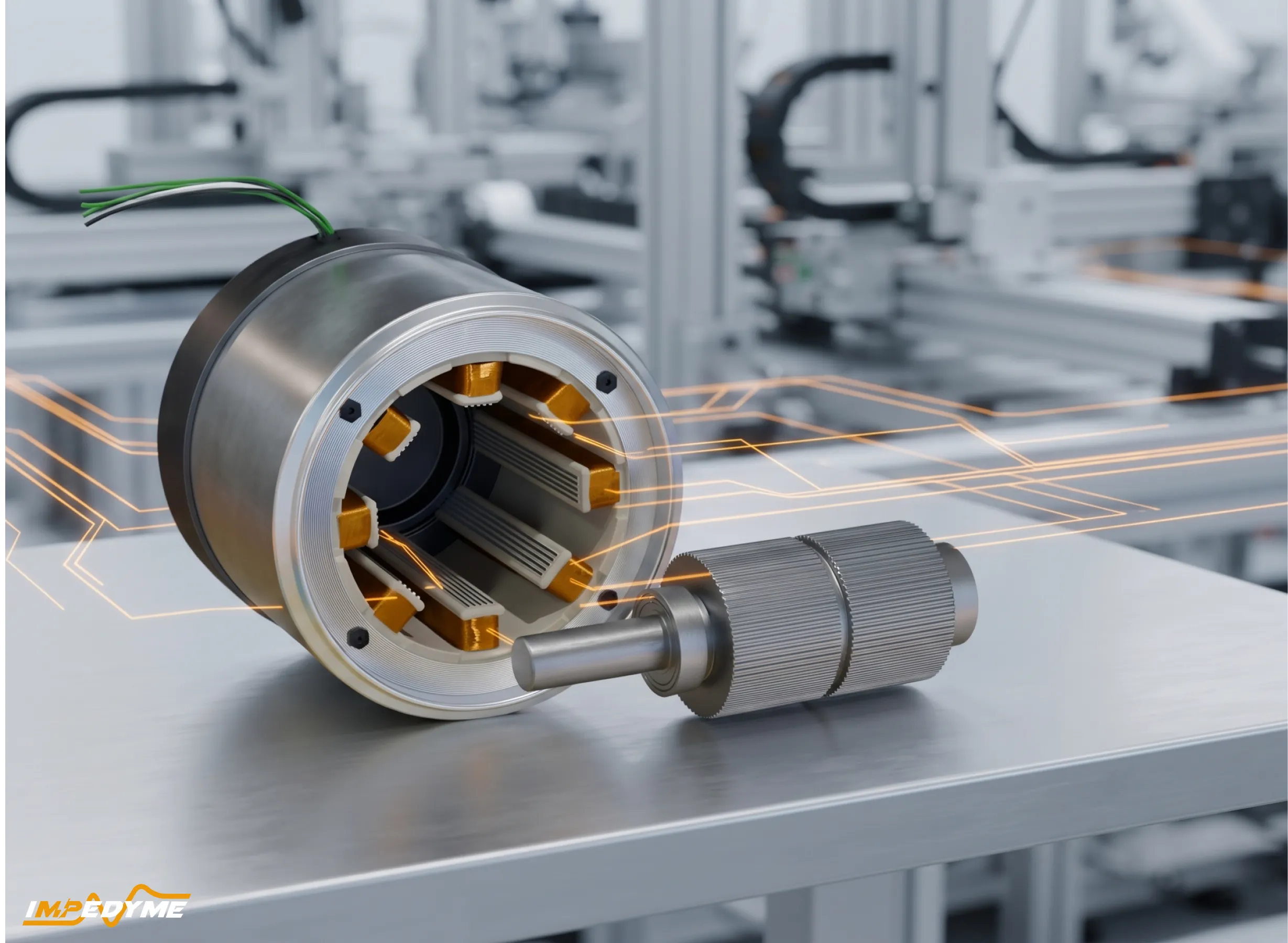
A stepper motor turns digital commands into discrete steps of rotation, so it can position a load without a feedback sensor. That only holds if the stepper motor driver, the supply and the torque margin keep the rotor synchronized with the commands. This guide is for power electronics, motor-drive and validation engineers. It covers what a stepper motor is, how the rotor constructions and windings differ (including small stepper motor and micro stepper motor formats), and how a stepper motor driver regulates phase current. It also explains how a stepper motor controller differs from the driver, where a closed loop stepper motor makes sense, and how to settle the servo motor vs stepper motor question with test data instead of rules of thumb.
A stepper motor is a synchronous electric machine whose rotor advances in fixed angular increments as current moves through its phase windings in sequence. Each winding group is called a phase. Most industrial motors have two phases, though three- and five-phase designs exist. The angle the rotor moves per full-step command is the step angle. When current stays applied without changing, the rotor holds its position against a static load. This is energized holding, and it disappears when the driver removes or cuts back the current.
One common example is a two-phase hybrid motor with a 1.8° step angle, which needs 200 full steps to complete one revolution, since 1.8° multiplied by 200 equals 360°. That figure is a property of one motor family, not a universal rating. Other motors are built for 0.9°, 7.5°, 15° or other angles.
Engineers need to separate two kinds of position. The commanded position is the step count the controller has issued. The measured position is what an encoder, optical sensor or other instrument reports. In an open-loop system the two agree only as long as no steps are lost.
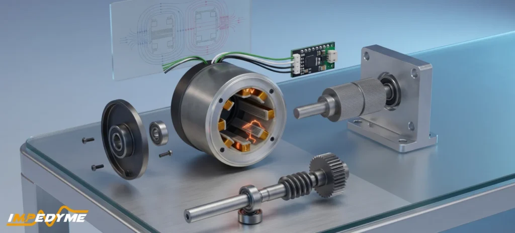
A practical stepper system has four separate parts:
Many integrated modules combine the controller and driver. Even then, motion planning and current regulation are different functions and should be specified separately. Keeping them separate also makes testing easier. Controller and driver behavior can be checked early against a motor emulator that reproduces the electrical load of the windings, before the real motor and mechanics are ready.
There are three main rotor constructions in a stepper motor: permanent magnet, variable reluctance and hybrid. They differ in how the rotor produces torque. That mechanism determines step angle, detent behaviour, cost and the torque available at a given size. Compare them by mechanism and application, not by catalogue listing.
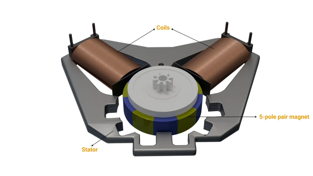
A PM stepper motor has a magnetized rotor, usually with poles arranged radially around its circumference. The rotor turns to line up its poles with the stator field as the driver switches it. Because the magnet attracts the stator iron even when unpowered, PM motors have detent torque: a small, notchy resistance you can feel when turning the shaft by hand.
Many PM motors are compact, low-cost “can-stack” designs with relatively coarse step angles. That makes them the usual choice for a small stepper motor or micro stepper motor in valves, vents, gauges, cameras and consumer devices. These motors are often sold with an integrated reduction gearbox. A geared actuator might advance its output shaft by a small fraction of a degree per step. That number is the gearbox output resolution, not the motor’s intrinsic step angle. The motor still steps at its native angle, and gear backlash and compliance sit between the rotor and the load.
A VR stepper motor has a soft-iron rotor with teeth but no magnet. When a stator phase is energized, the magnetic flux pulls the rotor toward the position that minimizes reluctance in the magnetic circuit, so the nearest rotor teeth line up with the energized poles. Energizing the next phase moves that low-reluctance position along, and the rotor follows.
Because the rotor is unmagnetized, a VR motor has essentially no magnetic detent torque when unpowered, and the shaft turns freely. Do not confuse this with energized holding torque, which a VR motor does produce while a phase carries current. VR motors are relatively uncommon in new designs, but they show the reluctance principle that hybrid motors also use.
A hybrid stepper motor combines both principles. An axially magnetized permanent magnet sits between two toothed rotor cups. One cup’s teeth become north poles and the other’s south poles, and the two cups are offset by half a tooth pitch. The stator poles carry matching teeth. This geometry concentrates flux in many small air-gap regions. That is why hybrids combine fine full-step angles with substantial holding torque for their size.
Common full-step angles for hybrids are 1.8° (200 steps per revolution) and 0.9° (400 steps per revolution). This is the motor’s mechanical step angle. It is not the same as microstep command resolution, which the driver produces by dividing each full step electrically. A 1.8° motor running on a 1/16 microstepping driver accepts finer commands, but its construction has not changed.
Type Mechanism and characteristics Applications and limitations
Permanent magnet Magnetized rotor aligns with the switched stator field. Has unpowered detent torque but commonly coarser intrinsic steps. Compact geared mechanisms and intermittent positioning. Main limitation: relatively coarse native step size.
Variable reluctance Unmagnetized toothed rotor seeks minimum reluctance. Offers little or no permanent-magnet detent torque and resolution depends on tooth geometry. Educational, specialized, or low-inertia mechanisms. Main limitation: no magnetic holding when unpowered.
Hybrid Permanent magnet with offset toothed rotor cups. Provides unpowered detent torque and supports fine full-step angles. Machine axes, robotics, automation, and instrumentation. Main limitations: resonance, heating, and reduced torque at high speeds.
A unipolar stepper motor typically energizes one half of a center-tapped winding at a time, allowing magnetic polarity to change without reversing current through that half-winding. A bipolar stepper motor reverses current through each complete phase, normally using an H-bridge. The available copper utilization, resistance, inductance, current rating, and driver requirements therefore depend on the connection.
Four-lead motors normally expose two independent bipolar phases. Five-lead arrangements commonly join center taps internally and are generally intended for unipolar excitation. Six-lead motors expose two center taps; each full winding may sometimes be driven bipolarly if the manufacturer permits it and the center taps remain isolated. Eight-lead motors expose separate half-windings and can commonly be configured as unipolar, bipolar series, or bipolar parallel.
For an eight-lead motor, series connection usually presents higher phase resistance and inductance than parallel connection. Parallel connection generally requires more driver current and can establish current faster. Neither should be selected from a universal torque claim: use the manufacturer’s connection-specific phase-current, resistance, inductance, thermal, and torque-speed data.
| Connection | Wiring and current path | Switching, options, and trade-offs |
|---|---|---|
| Bipolar, fixed | 4 leads; current flows through the full phase winding. | Requires two H-bridges. Normally fixed; simple wiring, but ratings are connection-specific. |
| Unipolar, common taps | 5 leads; current flows through one half-winding at a time. | Uses low-side or equivalent switches. Usually fixed, with simpler switching but restricted reconfiguration. |
| Center-tapped | 6 leads; supports half-winding unipolar or full-winding bipolar operation. | Switching depends on the method. May support either configuration; confirm center-tap isolation and ratings. |
| Separately exposed halves | 8 leads; half-windings are independently accessible. | Supports unipolar, series, or parallel configurations. Offers maximum flexibility but requires careful phasing. |
A gearbox, encoder, lead screw, and power supply are system choices, not winding types. A center-tapped motor can use a bipolar stepper motor driver only where its accessible winding arrangement and ratings support that connection.
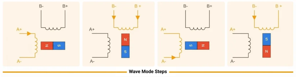
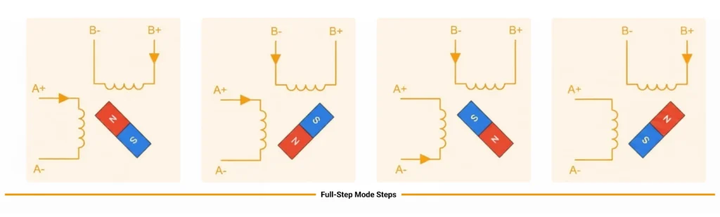
Take a two-phase bipolar stepper motor and drive it with a simple full-step sequence: phase A positive, then phase B positive, then phase A negative, then phase B negative, and repeat. Each change in phase current moves the stable magnetic alignment, the position where the rotor and stator fields would be in equilibrium. The rotor follows this moving equilibrium only if the available torque exceeds the load torque and the torque needed to accelerate the rotor and load inertia.
The command interface is simple:
Pulse count commands displacement.
Pulse rate commands speed.
Direction reverses the phase sequence.
The full-step angle is one revolution divided by the number of full steps per revolution. In a conventional two-phase hybrid design, each full step moves the rotor by one-quarter of a rotor tooth pitch. A rotor with 50 teeth therefore gives 200 full steps and a 1.8° step. A 100-tooth rotor gives 0.9°. This tooth-count relationship applies to that standard two-phase hybrid geometry, not to every stepper design.
Step counting alone cannot detect a stall. The controller increments its position counter whether or not the rotor moves. If the load jams, acceleration is too aggressive, or current collapses, the rotor can slip by one or more pole pitches or stop altogether while the commanded position keeps increasing. Without an encoder, a limit switch, or a driver-level stall-detection feature, the system has no way of knowing whether the commanded movement was completed.
All driving techniques sequence the phase currents. They differ in whether each phase is simply switched on and off or set to intermediate current levels. The motor’s mechanical full-step angle stays the same. What changes is the set of electrical current commands between full-step positions.
| Mode | Excitation and commands per revolution | Smoothness and torque characteristics |
|---|---|---|
| Wave drive | One phase on at a time; 200 commands for a 1.8° motor. | Rough motion with pronounced step ringing. Compare torque with two-phase-on drive at equal phase current and thermal conditions. |
| Full step | Two phases on at a time; 200 commands per revolution. | Rough at low speeds. Higher static torque than wave drive at equal per-phase current, but greater copper loss. |
| Half step | Alternates between one and two phases on; 400 commands per revolution. | Smoother than full-step operation, but torque ripples between one-phase and two-phase positions unless current is compensated. |
| Microstepping (1/16) | Approximately sine- and cosine-weighted currents; 3,200 commands per revolution. | Smoothest motion, with reduced vibration and noise. Each microstep provides less incremental torque, and command resolution does not equal positioning accuracy. |
Wave drive energizes one phase at a time: A positive, B positive, A negative, B negative. It is the simplest sequence to generate and draws the least total current. Claims that wave drive “delivers less torque” than two-phase-on full stepping are only meaningful when both cases use the same stated phase current and the same thermal assumptions. Two energized phases at the same per-phase current produce more torque, but they also dissipate more heat.
Full-step mode energizes two phases at once. The stable position sits between the poles, and each command still moves the rotor one full step. For the example 1.8° motor, 200 commands complete one revolution. Datasheets often quote holding torque with both phases at rated current, but “rated torque” means nothing unless the drive mode, phase current, winding connection and temperature conditions are stated with it.
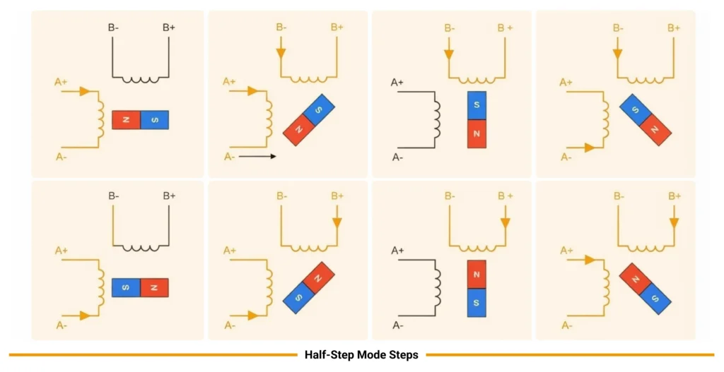
Half stepping alternates between one-phase-on and two-phase-on states. That doubles the number of stable positions, so the example motor needs 400 commanded half steps per revolution. Because one-phase and two-phase states produce different torque at equal per-phase current, plain half stepping causes torque ripple. Some drivers compensate by raising current in the single-phase state to even out torque, as long as winding and thermal limits allow it.
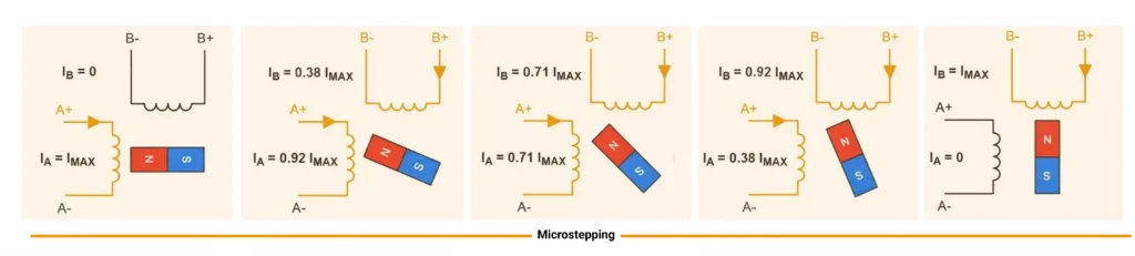
With microstepping, the stepper motor driver doesn’t just switch phases on and off. It sets both phase currents to intermediate levels, so the combined field, and the rotor, can stop between full-step positions. The figure shows one full step divided into four microsteps:
Phase A follows a cosine profile and phase B a sine profile. That keeps field strength nearly constant while only its direction rotates. Compared with half stepping, this gives smoother motion, less vibration and lower noise.
A 1/16 driver applies the same principle with 16 levels per step. Each 1.8° full step becomes 0.1125°, or 3,200 commands per revolution. Keep three quantities apart:
The stepper motor controller decides where and how fast to move. The stepper motor driver decides how much current flows in each phase, and how quickly that current can be established. Most high-speed performance problems are driver and supply problems rather than controller problems.
Each phase of a stepper motor is a resistance in series with an inductance, plus a back-EMF that grows with speed. Three relationships describe how it behaves:
Steady-state current is set by the supply voltage divided by the winding resistance, once the inductance has stopped opposing change.
The electrical time constant is the winding inductance divided by its resistance. It sets how many milliseconds the current takes to settle under a plain voltage drive.
The initial rate of current rise after switching is roughly the applied voltage divided by the inductance. Higher inductance slows the rise, and higher voltage speeds it up.
These are idealized starting points. Back-EMF, the PWM switching pattern, and the driver’s own voltage drops all change the real waveform. At high step rates, each step lasts only a short time. Current may not reach its target before the next commutation, and the back-EMF the motor generates eats into the voltage available to force current in. That is the electrical reason torque falls with speed.
Simple L/R drive applies a fixed voltage, often the motor’s rated voltage, so the winding resistance alone limits current. To speed up current rise, older designs added series resistors and raised the supply. That shortens the time constant, but it wastes power as heat in the resistors.
Constant-current (chopper) drive applies a supply voltage well above the winding’s resistive drop, then regulates current with high-frequency PWM. The driver measures phase current, switches off at the target value, and lets the current decay through a recirculation path before switching on again. Key features include:
Current limit setting, which sets the peak or RMS phase current. Match it to the motor’s connection-specific rating.
Supply-voltage limit, the driver’s maximum rated voltage, which sets the ceiling on high-speed performance. Choose the supply from the driver’s absolute maximum rating and the motor’s insulation and thermal limits. Do not choose it from a generic voltage multiplier.
Decay modes. Slow decay recirculates current through the low-side switches, giving low ripple but sluggish tracking of falling current. Fast decay reverses the applied voltage so current falls quickly, at the cost of more ripple. Mixed and adaptive decay modes switch between the two to follow the commanded sine wave, especially on falling-current segments and at speed.
Idle-current reduction, which cuts phase current after a period at standstill to reduce motor heating. Holding torque drops in proportion, so confirm the reduced current still holds the load.
A clearly hypothetical illustration for engineers to check against real datasheets: take a winding of 1.5 Ω and 3 mH rated at 2 A. Under plain L/R drive, it would need about 3 V to reach 2 A, with a time constant of about 2 ms. A chopper drive on a 24 V supply would initially push current up about eight times faster, reaching 2 A in roughly a quarter of a millisecond if back-EMF is ignored. These numbers are an idealization. Real values must come from the stepper motor and driver datasheets and from measured phase-current waveforms.
No single stepper motor torque value establishes whether a move will succeed. Selection requires torque at the required speed and acceleration, under stated driver, current, voltage, winding, temperature, and load-inertia conditions.
| Term | Physical meaning | Selection consideration |
|---|---|---|
| Holding torque | Maximum static resisting torque before loss of stable position | Check static holding at the specified current. |
| Detent torque | Magnetic resisting torque without phase current | Assess unpowered rotor feel or passive holding. |
| Pull-in torque | Load torque permitting direct start, stop, or reversal | Check the start-stop operating region at the specified speed and inertia. |
| Pull-out torque | Maximum sustainable running load before synchronism is lost | Check the running torque-speed curve. |
| Acceleration torque | Torque required to accelerate the motor and reflected inertia | Size the torque for the required motion profile. |
Holding torque is the maximum static torque a stepper motor can resist under specified phase-current and thermal conditions before it leaves the intended stable equilibrium. It is not the available torque at every speed.
Detent torque is the unpowered magnetic torque caused mainly by permanent-magnet and toothed geometry. A variable-reluctance rotor may have little or none, while permanent-magnet and hybrid constructions generally exhibit it.
A rotor can lag its commanded equilibrium under a static load without missing a complete step. A simplified sinusoidal torque-angle plot can illustrate increasing restoring torque followed by instability, but it is not an exact curve for every motor.
Pull-in torque describes the load under which a stepper motor can start, stop, or reverse at a stated command rate and specified load inertia without an acceleration ramp. Pull-out torque is the maximum load torque sustainable after the motor is already running at a stated speed.
The central selection graphic is the torque-speed curve. Below the pull-in boundary is the direct start-stop region. Between pull-in and pull-out curves is a ramp-required region: the motor may run there but cannot jump instantly to that speed. Above the pull-out boundary, synchronism is not expected under the documented conditions.
Torque generally falls with speed because winding inductance limits current rise and back-EMF reduces the net voltage available to force current. Mechanical losses and driver behavior also matter. There is no universal corner speed or exact inverse-speed law.
Acceleration ramps are needed because the electromagnetic torque margin must accelerate both rotor and reflected load inertia. An abrupt command may demand more torque than the motor can produce even when steady running at the final speed would be possible.
Every curve must identify driver type, supply voltage, phase-current setting, winding connection, temperature conditions, and test inertia.
Advantages, with their conditions:
Disadvantages:
A stepper’s “precision” belongs to its geometry and drive. It is not guaranteed in operation. Real accuracy is whatever the system delivers under load.
Gearboxes, belts, lead screws and linear actuators convert or scale motor motion. A “linear stepper” is a stepper motor with an integrated screw, not a separate kind of motor.
Each step excites the rotor and load like a spring-mass system. The rotor overshoots and rings around the new equilibrium before settling. When the step rate falls near the natural frequency of that system, the oscillations can build up.How much depends on load inertia, available torque, damping (mechanical friction, viscous loads and the driver’s electrical behaviour) and command timing.
Low-speed resonance is mainly this mechanical ringing. It is most visible in full-step and half-step modes and is reduced by microstepping and damping. Mid-speed instability is a separate phenomenon. It involves interaction between rotor oscillation, back-EMF and the driver’s current regulation, and can cause a sudden loss of torque in a particular speed band. Both depend on the motor, load and driver, so there is no universal frequency range to avoid.
The categories overlap, so be clear about terms. “Servo” describes a feedback-controlled system. “BLDC” describes a motor construction. A BLDC motor running position control with an encoder is a servo system, and a stepper motor with an encoder and position loop can be one too.
| Option | Performance and load handling | Setup and power characteristics |
|---|---|---|
| Open-loop stepper | No position verification; low-to-moderate speed; needs a large torque margin | Minimal tuning; often high heating at rest; lowest complexity |
| Closed-loop stepper motor | Encoder-based error correction; low-to-moderate speed, sometimes extended; handles load variations better | Moderate tuning, often preset; lower heating with load-adaptive current; moderate complexity |
| Servo system (e.g., BLDC/PMSM with encoder) | Continuous position feedback; wide speed range, including high speed; handles changing loads and peaks | Requires loop tuning; low heating at rest; highest complexity |
| BLDC with speed controller (no position loop) | Hall or sensorless commutation; wide speed range; good speed regulation under varying loads | Requires speed-loop tuning; low heating at rest; moderate complexity |
Conditional selection rules for the stepper motor vs servo decision:
The following is a clearly hypothetical horizontal lead-screw axis, used only to show the method:
Step 1 — Rotational speed. A travel speed of 200 mm/s on a 10 mm lead means the screw must turn 20 revolutions per second, or 1,200 rpm. For a 1.8° motor that is 4,000 full steps per second. At 1/16 microstepping the controller must issue 64,000 pulses per second.
Step 2 — Reflected load inertia. In an idealized model, a mass moving on a lead screw appears at the motor shaft as an inertia equal to the mass times the square of the lead expressed as distance per radian. A 10 mm lead corresponds to about 1.59 mm of travel per radian. The 5 kg mass therefore reflects roughly 127 g·cm², which is about 1.5 times the example rotor inertia.
Step 3 — Angular acceleration. Reaching 20 revolutions per second (about 126 rad/s) in 0.1 s requires about 1,260 rad/s².
Step 4 — Required torque. Multiply the total inertia (rotor plus reflected, about 209 g·cm²) by the angular acceleration. That gives roughly 0.026 N·m of acceleration torque. Adding the assumed 0.02 N·m friction gives about 0.046 N·m needed at the end of the ramp, at 1,200 rpm.
What this idealized model leaves out: screw inertia, coupling inertia, screw efficiency, vertical gravity load (for non-horizontal axes), process forces, backlash and duty-cycle heating. Each of these can dominate in a real design.
Step 5 — Check against the curve. Plot the acceleration point and the constant-speed running point on the manufacturer’s pull-out torque-speed curve, measured with your intended driver, voltage and current setting. Then apply an explicitly chosen design margin, for example requiring available torque of at least twice the calculated requirement at every point. Document the factor you choose and why.
Step 6 — Check the drive. Confirm the driver’s continuous and peak current rating, the supply voltage needed to hold torque at 1,200 rpm, and motor and driver temperatures over the real duty cycle.
A frame designation such as a standardized faceplate size describes mounting dimensions only. It says nothing about torque, current or inductance, and two motors with the same frame can perform very differently. Read the phase current, resistance, inductance, rotor inertia and torque-curve test conditions from the actual datasheet before selecting a stepper motor.
Transmission options:
Stepper motor driver validation should follow a disciplined sequence with a real motor and a representative load:
A bench or dynamometer setup with the actual motor remains the reference for stepper validation, because the motor’s nonlinear magnetics, detent torque and resonance are what the driver has to handle. Power hardware-in-the-loop (PHIL) can replace the physical motor only if a confirmed emulator reproduces the relevant stepper phase electrical behaviour (two-phase H-bridge loading, inductance, position-dependent back-EMF and detent effects) and the driver’s interaction with it at the required bandwidth.
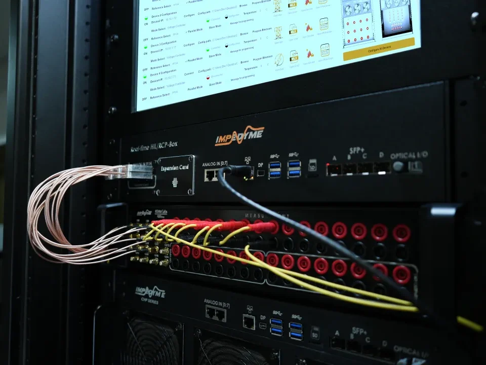
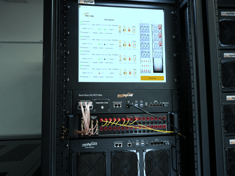
Impedyme’s motor emulation stack is built for FPGA-based Hardware in the loop and Power Hardware in the Loop testing of motor drives. MotorSim Studio configures and manages real-time motor emulation, including fault injection (phase shorts, open phases, sensor failures) and built-in waveform monitoring.Impedyme’s PHIL page lists “model libraries for PMSM, ASM, BLDC, IPM, and other machine types,” and its BLDC emulator page adds brushed DC motors. Impedyme does not currently list stepper motors among its supported emulated machines, so treat stepper-specific emulation as something to confirm with Impedyme engineering before planning around it. The CHP Series, Impedyme’s combined HIL and power platform, runs FPGA motor models that update “every 90 ns (~11.1 MHz),” according to Impedyme’s drone motor-emulator page. Impedyme states the platform supports signal-level and power-level emulation. The HIL/RCP-Box supports rapid control prototyping with PWM, encoder (ABZ) and analog I/O. That makes it a candidate for prototyping stepper motor controller and current-regulation firmware against a real power stage. FPGA Scope captures internal FPGA signals and measured waveforms; Impedyme describes up to 16 simultaneous channels at sub-microsecond resolution. PowerHIL Studio orchestrates automated test sequences with configurable limits, and the Impedyme Simulink Blockset moves Simulink models onto the real-time target. For stepper programmes, the most defensible uses today are controller prototyping, automated test orchestration and high-speed signal capture around a physical motor-and-load bench. Full stepper PHIL emulation should wait for engineering confirmation.
Selecting a stepper motor is a sequence, not a single catalogue choice. First set the motion profile: travel, speed, acceleration, load and how costly a missed step would be. Then choose the rotor construction and winding connection, from a micro stepper motor or small stepper motor for compact geared actuators to a hybrid motor for finer full steps. Next, match a stepper motor driver and supply that can establish rated current at the target speed, and keep the stepper motor controller‘s motion planning separate from current regulation. Check every operating point against a real torque-speed curve with explicit margin, settle the stepper motor vs servo question (or choose a closed loop stepper motor) on the basis of required verification and dynamics, and finally validate measured position and temperature under real load before trusting the design.
What does a stepper motor driver do?
It converts step and direction commands into regulated phase currents, usually through H-bridges with PWM current chopping.Its current setting, voltage rating and decay modes largely determine high-speed torque and smoothness.
Stepper motor vs servo: which should I use?
Use a stepper when loads are predictable, speeds are moderate and simple open-loop positioning is acceptable. Use a servo system when you need high speed, strong dynamic response or guaranteed position under changing loads. Decide using the torque-speed curve at your operating points, not a general preference.
Is a closed loop stepper motor worth it?
It is often worth it when a missed step is costly or standstill heating matters, because the encoder confirms position and can allow load-adaptive current. Whether it extends usable speed or torque depends on the specific drive, so compare measured curves.
What is a micro stepper motor or small stepper motor used for?
Compact PM and small hybrid steppers drive camera lenses, valves, vents, gauges, medical pumps and consumer devices, often through integrated gearboxes. Judge them on output torque, gear backlash and duty cycle from the specific actuator’s ratings.
What is the difference between a stepper motor controller and a driver?
The controller plans the motion: how many steps, in which direction and on what acceleration profile. The driver is the power stage that delivers current to the windings. They can sit in one module, but they are specified, tuned and tested as separate functions.