

6 月 18, 2026
应用知识电网电机产品知识网络研讨会
-
 Invert…
-
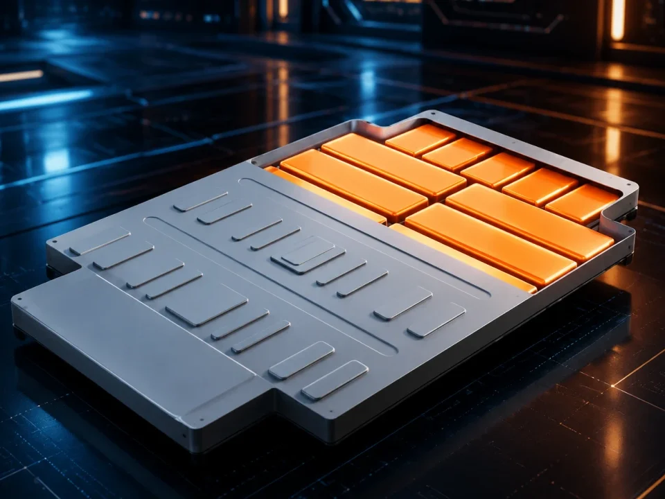
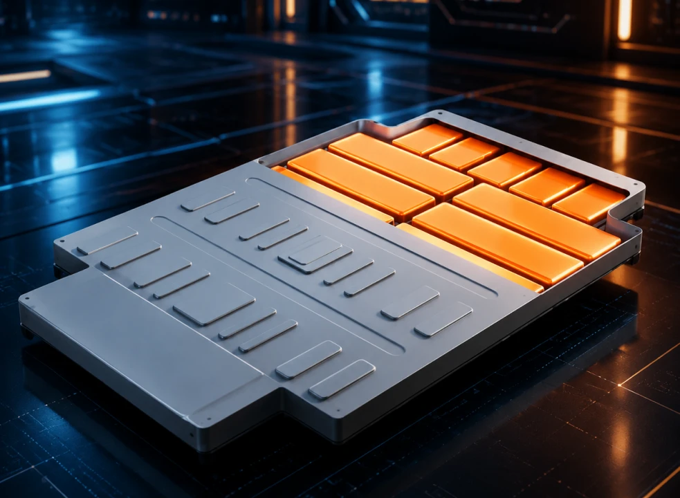
Batter…
-
HVDC P…
-
DC-DC …
-
Batter…
-
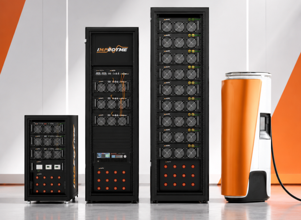
AI Dat…
-
DC Fas…
-
Data C…
-
De-Ris…
-
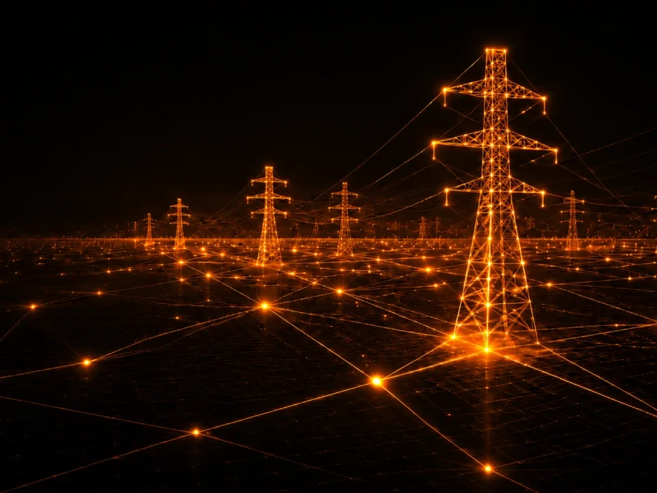
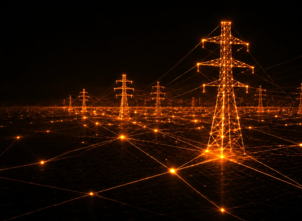
Grid S…
-
Megawa…
-
Stabil…
-
Webina…
-
BLDC M…
-
Motor …
-
EMC Co…
-
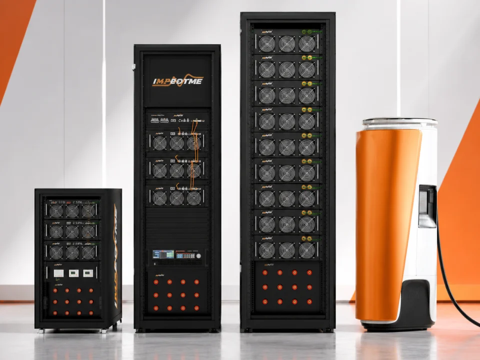
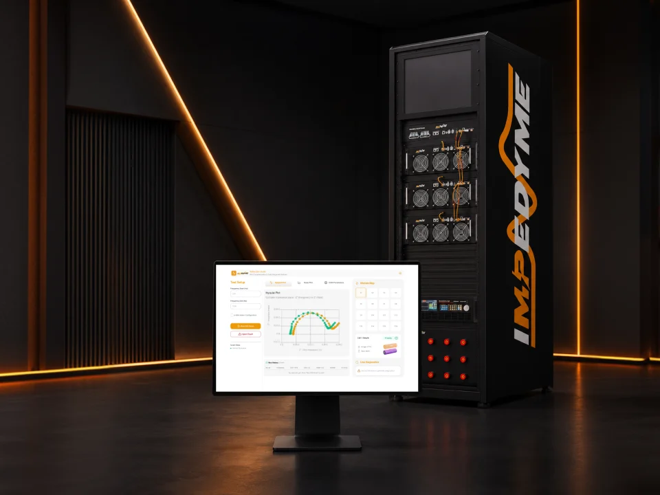
Impedy…
-
Your H…
-
Real T…
-
HVDC T…
-
Induct…
-
Automo…
-
DC/DC …
-
PWM Co…
-
BLDC M…
-
Electr…
-
DFIG W…
-
Dual A…
-
EV Dyn…
-
Electr…
-
Three-…
-
Three-…
-
Grid-C…
-
Grid-T…
-
Torque…
-
Wye-De…
-
IPMSM-…
-
Simpli…
-
Simpli…
-
Series…
-
Three-…
-
Ventur…
-
Microg…
-
Three-…
-
Field-…
-
Interi…
-
Perman…
-
PMSM R…
-
PMSM-B…
-
Maximu…
-
Six-Ph…
-
Synchr…
-
Single…
-
Three-…
-
Totem-…
-
Twelve…
-
Two-Wh…
-
Vienna…
-
High-V…
-
Wirele…