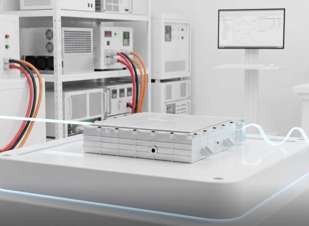

Inverter test is the process of evaluating the performance, efficiency, reliability, and safety of an inverter, a power electronic device that converts direct current (DC) into alternating current (AC). It ensures that the inverter operates correctly under various operating conditions and complies with applicable performance and safety standards. Different applications require specialized testing; for example, Low-voltage restart and control margin focuses on grid synchronization, anti-islanding, and efficiency, while motor drive inverter testing evaluates motor control, thermal performance, fault protection, and functional safety in electric vehicles. This guide provides an overview of inverter testing methods, procedures, and the equipment used to validate inverter performance.
Inverter testing is the structured, multi-disciplinary validation framework used to confirm that DC-to-AC and AC-to-DC power conversion meets strict operational specifications, efficiency targets, and safety standards across all design boundaries. It is not a single, isolated measurement; rather, it encompasses a comprehensive battery of physical inspection, static electrical checks, dynamic load profiling, fault injection, thermal evaluation, and firmware verification.
At its core, inverter testing checks both the high-power hardware stage and the low-voltage embedded control system. The power stage consists of solid-state semiconductor switches, gate drivers, bulk direct current link capacitors, magnetic output filters, and cooling channels. The control system runs sophisticated microsecond-level algorithms—such as Field-Oriented Control, space vector pulse-width modulation, or grid-synchronization phase-locked loops—to govern semiconductor switching. An effective inverter test validates how these physical and algorithmic elements interact under ideal conditions as well as extreme electrical, thermal, and environmental stress.
An inverter converts DC into controlled AC, and it sits at the center of almost every electrified system — so when it misbehaves, the whole product does. Inverter testing exists in three distinct contexts, and confusing them is where teams waste money, because each context demands a different kind of inverter test bench.
Development and design validation. During development, testing answers whether the design meets its targets: efficiency, thermal behavior, control stability, protection response, and compliance. This is the most demanding context because engineers deliberately push the inverter to its corners — full torque, weak grids, fault conditions — before any of it is safe to try in a real vehicle or on a live feeder. A development inverter test bench therefore has to be flexible and instrumented enough to reproduce those corners on demand. Catching a control-loop instability or a slow overcurrent trip here costs a firmware revision. Catching it in the field costs a recall.
Production quality assurance. On the line, testing is about repeatability and throughput: every unit must match the validated golden sample within tolerance. End-of-line tests are shorter and pass/fail oriented, verifying output quality, protection trips, and insulation integrity fast enough to keep pace with production. Here the test bench is optimized for cycle time and consistency rather than exploratory depth.
Maintenance and troubleshooting. In the field, testing is diagnostic — confirming an installed inverter still performs, or isolating a fault to a failed capacitor, gate driver, or cooling fan. This is usually handheld-instrument work rather than bench work, though returned units are often re-tested on a bench to confirm the diagnosis.
The cost of failure scales with the application. A traction inverter fault can produce uncommanded torque, a safety-critical event. A grid-tied inverter that fails to disconnect during an outage can energize lines that utility crews believe are dead. An industrial drive failure can halt a production line for hours. Rigorous inverter testing — backed by a test bench matched to the job — is the cheapest insurance against all three.
Testing a power electronics converter requires a systematic, safety-first workflow progressing from unpowered baseline inspections to energized signal analysis and full-power stress sweeps. The following engineering guide outlines the complete operational sequence for executing an inverter test.
Before applying electrical power, technicians must perform thorough mechanical and physical checks.
SAFETY WARNING: DC BUS VOLTAGE AND CAPACITOR DISCHARGE
Direct current link bulk capacitors inside high-power inverters store lethal amounts of electrical energy long after primary power sources are disconnected. Operating at typical direct current bus levels—ranging from 400 volts to over 1000 volts—charged capacitors can cause fatal electric shock or high-energy arc flash events. Always verify that the direct current bus voltage has discharged completely to zero volts using a certified, high-voltage digital multimeter before opening enclosure panels, touching power terminals, or adjusting test leads. Never rely solely on visual indicator lights. If internal bleeder circuits fail, manual external discharge resistor probes must be applied by qualified personnel wearing appropriate personal protective equipment, including insulated safety gloves and face shields.
Insulation resistance testing checks the dielectric integrity of wire insulation and semiconductor substrates to ensure leakage currents cannot energize the grounded chassis frame.
Before closing primary contactors, measure the open-circuit output voltage of the programmable direct current power supply or battery emulator. Ensure the direct current source is configured strictly within the inverter’s rated operating input window (e.g., verifying 12V/24V/48V ranges for low-voltage units or 400V/800V windows for electric vehicle powertrains).
Engage pre-charge circuitry to gradually charge internal capacitors, suppressing inrush currents. Once the main contactors close, initiate a no-load command. Measure the resting alternating current output line-to-line and line-to-neutral voltages using a True RMS digital multimeter to confirm that output voltage regulation meets nominal specifications prior to applying load.
Connect a digital oscilloscope equipped with isolated high-voltage differential probes across the alternating current output phases.
While basic guides bypass low-level switching mechanics, rigorous engineering validation requires probing the gate drive signals directly at the semiconductor switch gates.
Evaluate power stage delivery by stepping through defined load levels using precision load banks or programmable electronic loads:
Systematically induce controlled abnormal conditions to verify that embedded software and hardware interlocks trip protective relays within required safety timeframes:
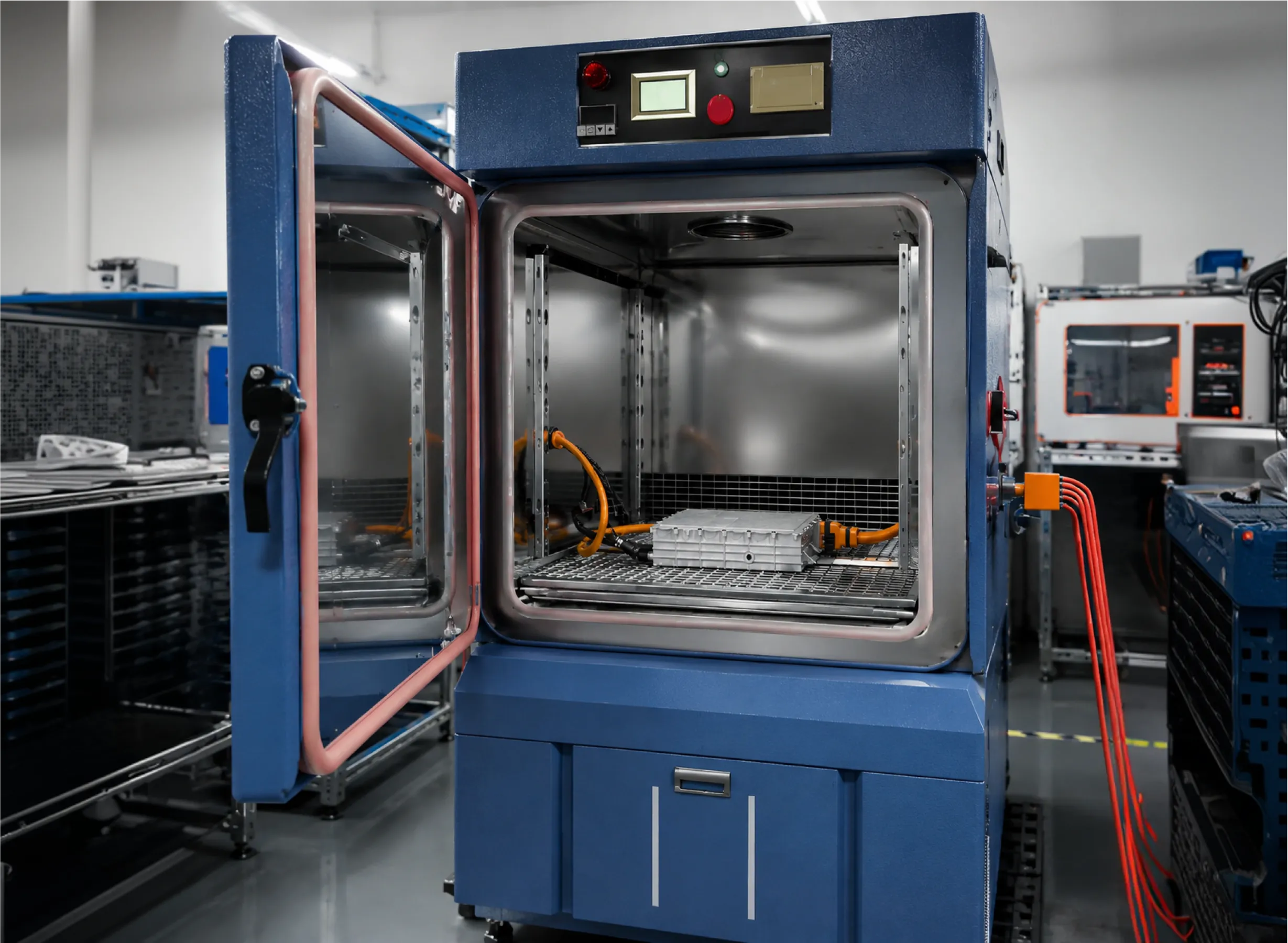
Operate the converter under full continuous rated load while tracking heat generation using thermal imaging cameras or embedded temperature sensors.
Connect a high-precision, wide-bandwidth power analyzer equipped with synchronized voltage and current channel inputs to measure total energy transformation quality.
Log all measured metrics—including no-load current, full-load efficiency curves, switching rise times, dead-times, trip response durations, and peak thermal rise—into a centralized data management workspace. Compare recorded operational parameters directly against manufacturer specification sheets and regulatory compliance standards to declare final pass/fail certification.
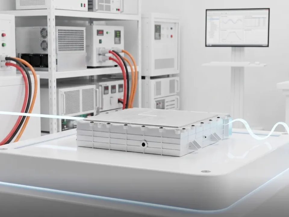
An inverter test bench is an integrated system, not a pile of instruments. Five subsystems have to work together.
DC input stage. A controllable DC source supplies the inverter’s bus, ideally programmable so you can sweep voltage across the operating range and reproduce battery or PV behavior. For bidirectional designs it must also absorb energy.
Load stage. The load must present realistic conditions to the output — resistive, reactive, or dynamic — from no-load to rated and into overload. Passive load banks are simple but inflexible; programmable and regenerative loads allow controlled, repeatable profiles.
Measurement and DAQ. A power analyzer for efficiency and harmonics, an oscilloscope for waveforms and switching, and a data-acquisition system to log everything synchronously. Measurement-chain accuracy directly limits the confidence of your efficiency and loss numbers.
Safety infrastructure. Interlocks, emergency stop, contactors, fusing, proper grounding, and enclosure protection. High-power benches store and move dangerous energy; safety is designed in, not added later.
Control and automation layer. Software to sequence tests, apply setpoints, capture results, and enforce limits. Automation is what converts a manual bench into a repeatable, high-throughput one.
There is a more powerful way to conceive the bench, though. Instead of wiring the inverter to a real motor, a real battery, and a real grid — each expensive, dangerous, and inflexible — an emulation-based bench replaces those with terminal-accurate emulators. A 驱动电机模拟器 presents the exact voltages and currents a real machine would at the inverter’s terminals; a battery emulator presents the exact DC-side behavior of a pack; a 器或电网仿真器 presents programmable grid conditions. This lets teams frontload validation, testing the inverter thoroughly and independently long before real components — or a real vehicle — exist. It is the architecture professional labs converge on, and it is the bridge from bench testing to HIL and PHIL.
No single measurement proves an inverter is good. A complete inverter test program layers several categories, each verifying a different failure mode. The table below summarizes the main categories, what each verifies, the qualitative thresholds engineers look for, and the class of equipment involved.
| Test category | What it verifies | Typical qualitative threshold | Equipment class |
|---|---|---|---|
| Functional / performance | Correct startup, output voltage and frequency, control response | Output tracks command; stable regulation across the operating range | Multimeter, oscilloscope, power analyzer |
| Waveform quality | Output is clean and low-distortion | Distortion below roughly 3 percent for pure-sine designs | Oscilloscope, power/harmonic analyzer |
| Load and overload | Behavior from no-load through rated load and controlled overload | Holds regulation to rated load; trips gracefully on overload | Programmable load or load emulator |
| Protection / fault response | Overcurrent, overvoltage, short-circuit, over-temperature trips | Detects and disconnects within the design window | Fault-injection setup, high-speed capture |
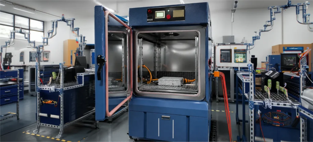
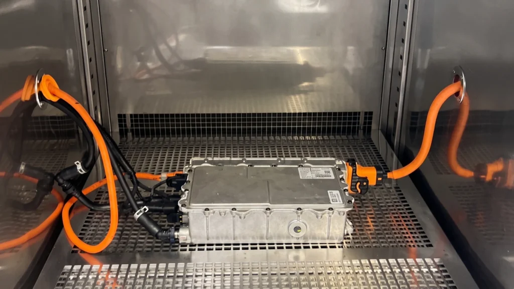
| Thermal | Temperature rise under sustained load | Junction and heatsink temperatures stay within rating | Thermal sensors, imaging, climate chamber |
| Insulation and safety | Dielectric strength and insulation resistance | Withstands rated test voltage without breakdown; high insulation resistance | Hipot tester, insulation tester |
| Grid compliance | Anti-islanding, voltage/frequency ride-through, power quality | Ceases to energize a formed island within about two seconds; rides through defined sags | Grid emulator, compliance software |
| Control / firmware verification | Control algorithms, state machines, sensor handling | Correct response to every commanded and fault state | HIL simulator, signal-level I/O |
| EMC pre-compliance | Conducted and radiated emissions from switching | Emissions trend below the applicable limit line | Spectrum analyzer, LISN, near-field probes |
The first six categories are within reach of a well-equipped bench. The last three — grid compliance, exhaustive control verification, and repeatable fault response — are where emulation and HIL methods become not just convenient but necessary, as we explain later.
Inverter testing is shaped by a family of international standards, each governing a different slice of the problem. Understanding which applies to your product prevents both over-testing and compliance gaps.
Related safety standards such as IEC 62109 (PV inverter safety) and IEC 61800-5-1 (drive systems) frequently appear alongside these, depending on the product’s market and application.
Executing an inverter test on a dedicated inverter test bench allows engineering teams to optimize performance parameters across opposing design trade-offs.
Engineers focus on achieving key technical milestones:
The manual bench is indispensable, but it hits four hard walls as validation deepens.
Destructive fault tests risk hardware. The faults you most need to prove — leg short-circuits, DC-link collapse, phase loss, over-speed — are exactly the ones that can destroy a real motor, pack, or the inverter itself. On a physical bench, you either avoid them or accept the risk and cost.
Corner cases are unrepeatable. Reproducing a precise voltage sag, a specific weak-grid impedance, or an exact transient by hand is nearly impossible. Without bit-for-bit repeatability, you cannot compare two firmware builds honestly.
No regression scalability. Every firmware revision ideally re-runs the full test suite. Manually re-executing dozens of scenarios for every commit does not scale, so coverage quietly shrinks under schedule pressure.
Manual cycle restarts. Each iteration means re-wiring, re-staging loads, and re-establishing conditions by hand — slow, error-prone, and impossible to run unattended overnight.
When you find you cannot inject the faults you worry about most because they would wreck hardware, that is the clearest signal you have outgrown the purely physical bench.
Hardware-in-the-Loop and Power Hardware-in-the-Loop testing solve exactly the problems above by putting the real world into software.
Signal-level HIL exercises the inverter’s controller — the brains — in closed loop against a real-time simulation. The controller sends its PWM gating signals into a model of the power stage, motor, battery, or grid, and receives simulated sensor feedback in return, all at signal level. This validates control logic, state machines, and protection without any power flowing. It is ideal for firmware verification and functional-safety fault injection.
Power-level PHIL goes further, closing the loop with real energy. The inverter’s actual power stage connects to a regenerative power interface that behaves like the emulated motor, battery, or grid, exchanging real current and voltage. This exposes the behaviors that only appear under real power — current limits, filter resonance, dead-time effects, sensor scaling, and switching-side delays — bridging the gap between pure simulation and a full prototype.
The fidelity of both hinges on how fast and deterministically the model runs. CPU-based real-time simulators are often limited to roughly 20–50 kHz by I/O latency, which is too coarse to resolve fast switching. Our platforms are built around FPGA-based real-time simulation with timesteps as low as 90 nanoseconds, fast enough to faithfully represent PWM ripple, switching transients, torque ripple, and the nonlinear, rotor-position-dependent behavior of real machines — the very ripple that triggers false overcurrent trips on real hardware and that average-value models miss. That temporal resolution also keeps the PHIL loop stable, because the power stage response is matched tightly to the simulation step.
Crucially, faults become safe and repeatable. Short circuits, phase loss, DC-link collapse, over-speed, and sensor faults can be injected as often as needed with zero risk to physical hardware, and every test starts from an identical programmable state — enabling automated regression campaigns and traceable pass/fail reporting suitable for certification evidence.
| 能力 | Traditional bench | Signal-level HIL | Power-level PHIL |
|---|---|---|---|
| Safety of fault testing | Risky; can destroy hardware | Very safe; no power flows | Safe; faults live in the model, not the hardware |
| Repeatability | Operator-dependent | Bit-for-bit repeatable | Bit-for-bit repeatable at full power |
| Fault coverage | Limited to non-destructive cases | Broad at signal level | Broad, including power-stage behavior |
| Cost per test cycle | High (staging, real components, wear) | Low once configured | Moderate; regenerative, no consumables |
| Automation / regression | Manual, hard to scale | Fully automatable | Fully automatable |
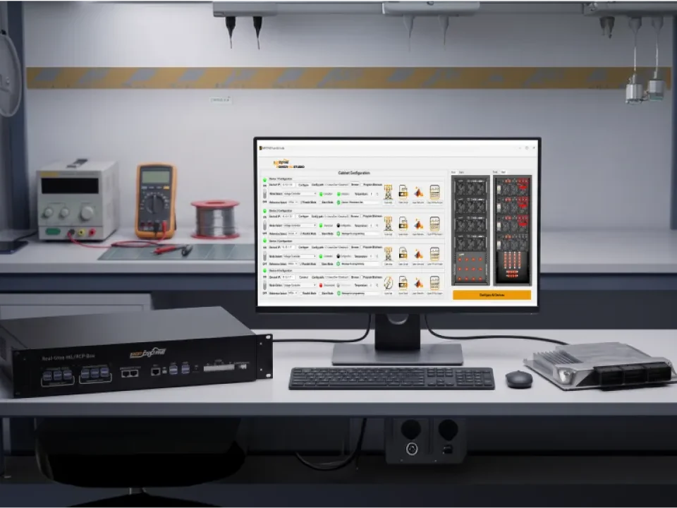
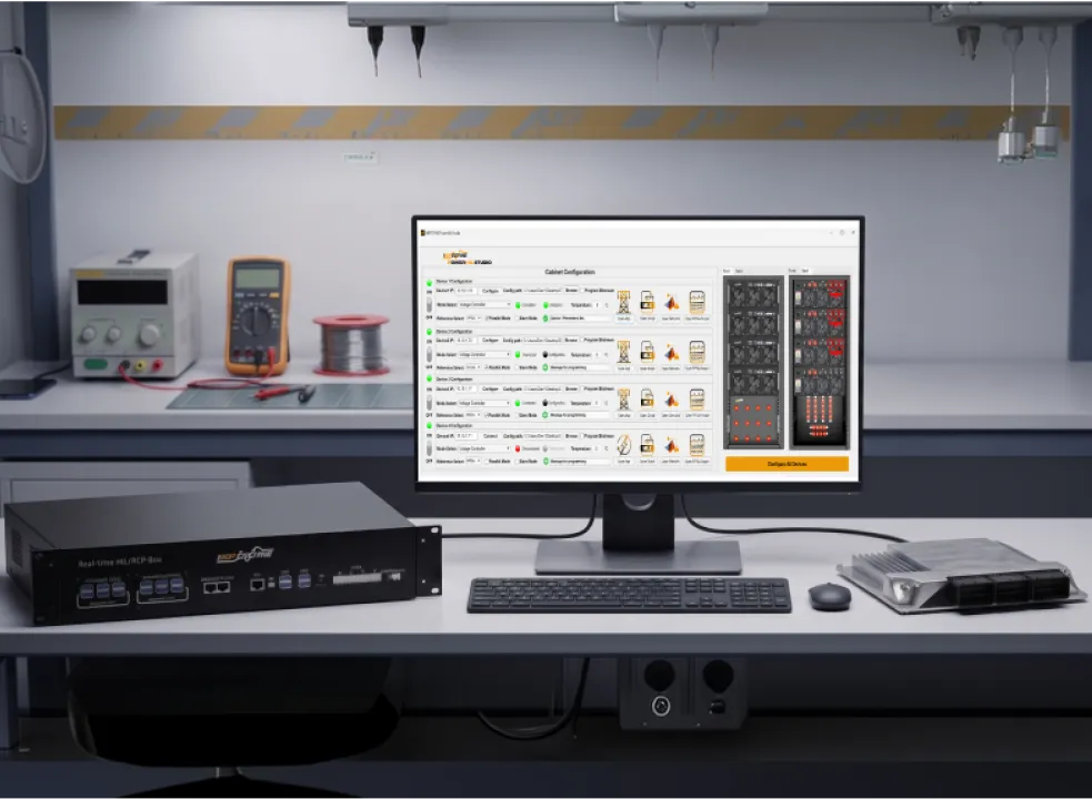
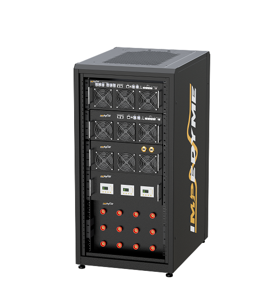
Several of our products make this workflow concrete for inverter testing. The CHP Series (Combined HIL and Power) testbench is the FPGA-based, regenerative platform that unifies signal-level HIL and full-power PHIL in one architecture, available in CHP-150 and larger CHP 300 configurations and scalable through paralleling. PowerHIL Studio, is the orchestration and automation layer — a scenario and sequence editor for drive cycles, ramps, step changes, and fault scenarios, with synchronized control of every emulator, automated pass/fail reporting of metrics like current ripple, torque ripple, efficiency, and protection response, and built-in limit management with controlled shutdown. MotorSim Studio provides high-fidelity motor and drive modeling (PMSM, induction, BLDC, and IPM machines) for traction and drive inverters. GridSim Studio handles grid emulation and compliance profiles for solar, grid-tied, and generator applications. BatterySim Studio, together with our 实时 电池仿真器, emulates the EV DC side at production voltage and current. FPGA Scope captures switching-level signals for diagnostics, and the Impedyme Simulink Blockset keeps the entire model-to-hardware workflow inside a MATLAB and Simulink environment.
Traction inverters in electric vehicles drive three-phase permanent magnet synchronous motors or induction motors, while managing energy recovery during regenerative braking.
Key traction ,使工程师能够在实验室环境中进行全尺度 focus areas include:
Photovoltaic inverters convert dynamic direct current generated by solar panels into synchronous alternating current injected into utility power grids.
Specialized solar inverter test methodologies include:
In megawatt-scale power generation—such as wind turbine nacelles, marine propulsion, and heavy diesel generator sets—a generator inverter test evaluates complex electro-mechanical interactions between physical generators and power conversion hardware.
Key generator inverter test considerations include:
Validating modern high-power inverters — especially those using wide-bandgap semiconductors — demands more than a conventional inverter test bench. It requires a unified real-time testing ecosystem engineered for sub-microsecond execution. We provide a complete hardware and software inverter test architecture designed to accelerate power electronics development.
Traditional real-time targets with slow processing cycles introduce severe phase lag and pulse-width modulation reproduction errors when interfacing with high-frequency switching converters — the single biggest limitation in high-power inverter testing. Our Combined Hardware-in-the-Loop and Power Hardware-in-the-Loop (CHP Series) platform solves this bottleneck by integrating execution processing and high-speed inputs and outputs directly on Field-Programmable Gate Array (FPGA) chips.
The CHP target achieves real-time simulation step times as fast as 1 microsecond, with internal model update times near 90 nanoseconds. This resolution keeps pulse-width modulation reproduction error below 1 percent, accurately capturing fast switching transients, sub-microsecond dead-time effects, and high-order harmonics without numerical instability — turning a full-power inverter test bench into a repeatable, switching-accurate instrument.
How do you test if an inverter is working properly?
Inspect it, then power it with no load and check output voltage, frequency, and waveform on an oscilloscope. Step the load up to rated, confirm it holds regulation and trips its protections, and measure efficiency and distortion with a power analyzer. Consistent in-spec results across all of these mean a healthy inverter.
What equipment do you need to test an inverter?
At minimum, a true-RMS multimeter, an oscilloscope, an insulation tester, and a controllable load, with a power analyzer for efficiency and harmonics. Professional validation adds programmable sources and emulation-based HIL and PHIL systems that stand in for real motors, batteries, and grids.
What is an inverter test bench?
An integrated system combining a DC input stage, a load stage, measurement and data acquisition, safety infrastructure, and a control layer. Modern benches replace real motors, batteries, and grids with emulators so the inverter can be tested independently, safely, and repeatably.
Can you test an inverter without a real motor or battery?
Yes. Emulation-based testing swaps the physical motor, battery, and grid for real-time models that reproduce their exact terminal behavior. This lets you validate the inverter fully — faults included — before real components exist, which is the core idea behind HIL and PHIL.
What is the difference between HIL and PHIL inverter testing?
Signal-level HIL tests the controller against a real-time model with no power flowing, ideal for control and firmware verification. Power-level PHIL closes the loop with real current and voltage, validating the actual power stage against emulated motors, batteries, or grids at full power.
How do you test an inverter generator?
Verify pure-sine waveform and low THD (below about 3 percent) across the load range, then apply load steps to check voltage and frequency stability. For parallel-capable units, confirm stable load sharing — programmable load and grid emulation makes all of this repeatable.