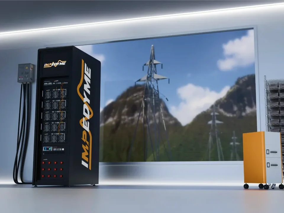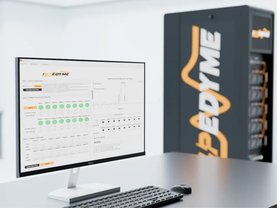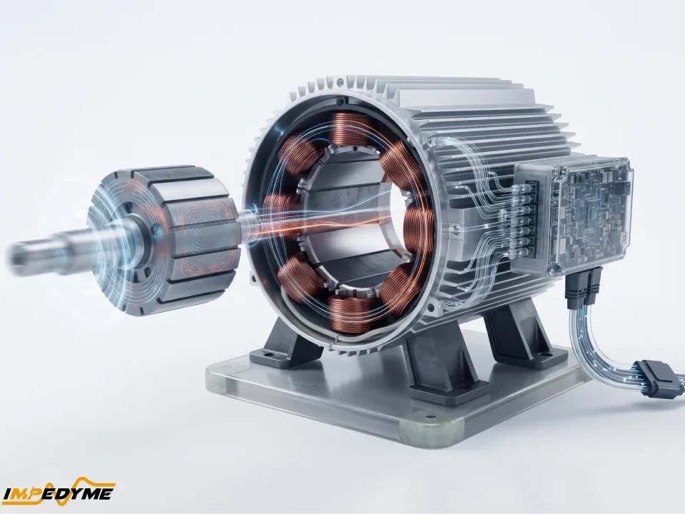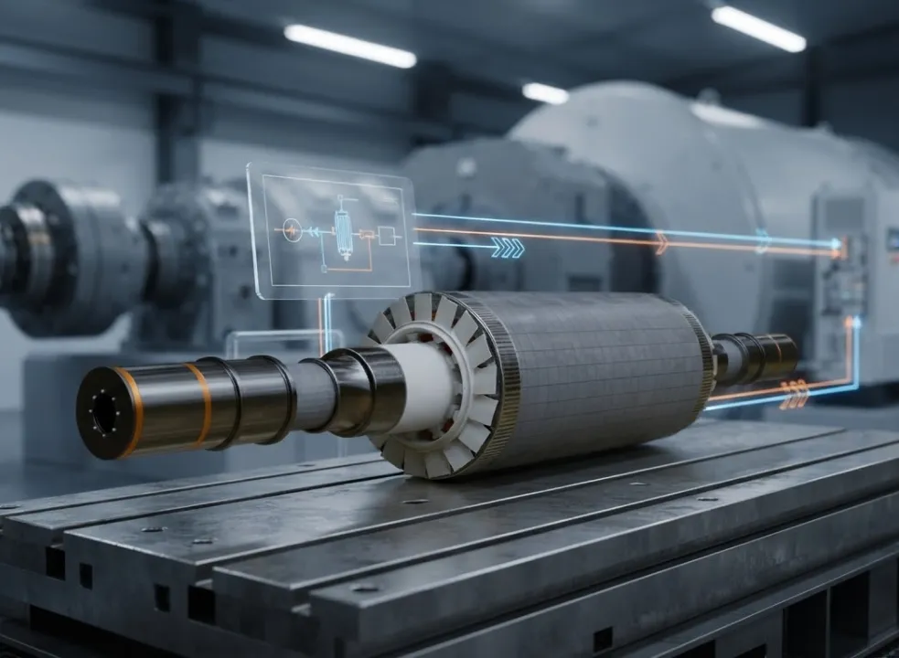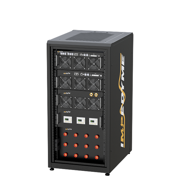
A BLDC motor emulator is an advanced test solution that replicates the dynamic electrical behavior of real motors—without using mechanical components or physical machines. These emulators are essential for validating Motor Control Units (MCUs), inverter power stages, and drive electronics used in electric mobility, robotics, drones, and industrial automation.
With the growing use of Brushless DC (BLDC) motors in automotive and robotics applications, the demand for reliable and scalable test platforms is increasing rapidly. Unlike traditional brushed motors, BLDC motors are quieter, lighter, and more efficient—but they require sophisticated supporting electronics, such as:
As systems grow more complex, part suppliers and OEMs must thoroughly test MCUs, inverters, and power electronics for reliability, robustness, and safety—without the cost and constraints of physical motor test setups.
A brushless DC motor, also known as an electronically commutated motor (ECM), is a permanent-magnet synchronous machine fed from a DC supply through a three-phase inverter. Every brushless electric motor has three building blocks:
Because the controller does the job the commutator used to do, the motor and the drive are one system. Neither half is meaningful alone.
The name causes confusion. It is called “DC” because it runs from a DC source (battery or DC link) and because its speed-torque behavior resembles that of a brushed DC motor: speed follows applied voltage, and torque follows current. Inside the machine, however, the windings carry alternating, switched currents. Connect a brushless DC motor directly to a plain DC source and it will not rotate; the rotor simply snaps into alignment with the energized winding and holds there.
A brushless electric motor removes the sliding electrical contacts that reverse current in a brushed DC motor. In the brushed design, carbon brushes contact a segmented commutator on the rotor, mechanically transferring and reversing armature current as the shaft turns.
Brush wear, conductive dust, contact voltage drop, friction loss, arcing, and broadband electromagnetic interference are inherent consequences. Brush bounce also constrains high-speed operation, while arcing can create an ignition concern in flammable environments. Electronic commutation generally reduces commutation EMI because controlled semiconductor transitions replace irregular mechanical contact interruption, although inverter switching still requires careful EMC design.
Moving the copper windings to the stator also places the main copper-loss source close to the housing and cooling path. This improves continuous power density relative to a rotating armature whose heat must cross an air gap and bearings.
Brushes retain one important advantage: a brushed motor can run directly from a battery without a three-phase controller.
Advantages
Disadvantages
| Aspect | Advantage | Disadvantage |
|---|---|---|
| Efficiency | No brush losses; wide high-efficiency region | Adds inverter conduction and switching losses |
| Lifetime | Bearing- and insulation-limited | Electronics add their own failure modes |
| Control | Precise torque and speed, regeneration | Requires firmware, position sensing, tuning |
| Environment | Sealed, spark-free, low EMI from commutation | Inverter PWM creates its own EMC challenge |
| Materials | High torque density from rare-earth magnets | Magnet cost, supply risk, demagnetization |
| Low speed | Smooth with sensors and FOC | Sensorless start-up and low-speed torque are weak |
| Application | Why BLDC wins | Typical control |
|---|---|---|
| EV traction and e-mobility (e-bikes, scooters, light EVs) | Power density, efficiency, regeneration | FOC, encoder or resolver; sensorless on small units |
| EV auxiliaries (coolant/oil pumps, HVAC blowers, electric power steering) | Sealed, long life, variable speed | Sensorless FOC for pumps and blowers; sensored FOC for steering |
| Aerospace actuators, fuel/hydraulic pumps, cabin fans | Reliability, no sparks, mass | Resolver-based FOC; sensorless for fans |
| Drones and UAVs (outrunners driven by ESCs) | Torque-to-weight, high speed | Sensorless six-step or sensorless FOC |
| HVAC compressors and fans, direct-drive washing machines | Variable-speed efficiency, low noise | Sensorless FOC |
| Cordless power tools | Power density, battery operation, durability | Hall-sensored six-step or FOC |
| Hard-disk spindles, cooling fans, printers | Smooth, quiet, long life | Sensorless; simple Hall-based drives for fans |
| Medical handpieces, infusion pumps, ventilator blowers | Sterilizable, quiet, precise | Sensored FOC; sensorless for blowers |
| Industrial servo axes, conveyors, cobots, exoskeletons | Dynamic response, precise positioning | Encoder-based FOC |
| Solar tracker actuators and solar water pumps | Direct DC supply, efficiency, low maintenance | Hall-sensored six-step; sensorless for pumps |
The pattern is consistent: positioning and low-speed torque demand sensors and FOC; fans, pumps and propellers, which never need full torque at standstill, tolerate sensorless start-up.
Every brushless DC machine combines a laminated stator with windings, a permanent-magnet rotor, optional position sensors, and bearings in a housing. The defining rule is the inverse of the brushed DC motor: the windings are stationary and the magnets rotate.
The stator is stacked from thin, insulated steel laminations to limit eddy-current loss. The slot count and winding type shape performance. Concentrated windings, wound around single teeth, give short end turns, high slot fill and cheap manufacturing. Distributed windings span several slots and produce a more sinusoidal back-EMF with lower harmonic content.
The three phases are connected in wye (star) or delta. In wye, two phases conduct in each six-step sector, and the star point serves as a natural reference for back-EMF sensing. In delta, every phase is involved at once.Because triplen (third-order) back-EMF harmonics add up around the closed delta loop, they can drive circulating currents that add losses and ripple. For the same wire and number of turns, a delta connection gives a speed constant roughly 1.73 times (the square root of three) higher than wye: the motor spins faster per volt but produces less torque per amp.
Slotless and ironless windings remove the stator teeth entirely. They eliminate cogging and have very low inductance, which is ideal for smooth, high-speed micro-drives. The trade-offs are a larger magnetic air gap, a tighter thermal limit, and a need for high PWM frequency to keep current ripple down.
Finally, the slot-pole combination largely determines cogging torque. Combinations where slots and poles share few common factors produce smaller, higher-frequency cogging.
Magnets are either surface-mounted (SPM) or buried in the rotor iron (interior PM, IPM). Surface magnets give nearly equal inductance on both rotor axes and almost pure magnet torque.Interior magnets create saliency, meaning different inductance along and across the magnet axis.That saliency adds reluctance torque, makes field weakening more effective, and gives sensorless controllers a signal to track at standstill.
Magnet material choices:
Supply risk is real. The International Energy Agency reports that China accounts for about 91% of global rare-earth separation and refining and 94% of permanent magnet production (sintered and bonded NdFeB), up from around 50% two decades ago. That concentration is why many design teams now evaluate ferrite or reduced-heavy-rare-earth designs.
A motor with more pole pairs completes more electrical cycles per mechanical revolution. Electrical frequency therefore rises with both shaft speed and pole-pair count, and a motor with more pole pairs needs a higher electrical frequency for the same shaft speed.
Illustrative example: an 8-pole (four pole-pair) motor turning at 6,000 rpm runs at an electrical frequency of 400 Hz. In six-step drive that means 2,400 commutation events every second.
More poles bring more torque per volume and smoother rotation. The cost is a higher electrical frequency, which brings more iron loss, a higher PWM and current-sampling rate, and more controller bandwidth. The same constraint makes high-speed, high-pole-count drives hard to emulate and test in real time.
Torque comes from the interaction between the stator’s magnetic field and the rotor magnets. The controller’s job is to keep the stator field roughly 90 electrical degrees ahead of the rotor field, the angle of maximum torque per amp. To do that the drive must always know where the rotor is, either by measuring it or by estimating it. Two commutation families exist: six-step (trapezoidal) and sinusoidal, the latter usually implemented as field-oriented control (FOC).
The electrical cycle is divided into six 60-electrical-degree sectors. In each sector one phase is driven high, one is driven low, and the third floats.PWM on the active switches sets the average applied voltage. That voltage sets the current, and current sets torque. A speed loop typically wraps around an inner current (or duty) loop.
Sector (electrical °) Hall state (A B C) Phase configuration (High / Low / Floating)
0–60 1 0 1 A / B / C
60–120 1 0 0 A / C / B
120–180 1 1 0 B / C / A
180–240 0 1 0 B / A / C
240–300 0 1 1 C / A / B
300–360 0 0 1 C / B / A
Six-step is simple and efficient in silicon, but it has known imperfections. Torque ripple appears at each transition because winding inductance prevents current from switching instantly between phases, so there is a commutation delay. Dead time in each inverter leg distorts the applied voltage. At high speed, controllers apply phase advance, commutating early so current can build before the back-EMF peak.
Most sensored BLDC motors use three Hall sensors spaced 120 (or 60) electrical degrees apart, producing six valid states per electrical cycle.That is exactly what six-step needs, but too coarse for smooth sinusoidal control at low speed. Higher-resolution options include incremental encoders, absolute encoders and resolvers. Resolvers are favored in traction and aerospace drives for their robustness to heat and vibration.
Sensors are frequent failure points. Typical problems are Hall misalignment relative to the back-EMF, Hall devices running past their temperature limits, and damaged cables or connectors.In a 120-degree layout the codes 000 and 111 never occur in normal operation, so their appearance is a standard diagnostic for a disconnected or failed sensor.Because these faults are common in the field and hard to stage on a running motor, sensor faults are among the most valuable things to inject during drive validation.
Sensorless six-step control watches the floating phase. When its back-EMF crosses the reference (the star point, or a virtual neutral built from resistors), the rotor is 30 electrical degrees away from the ideal commutation point. The controller measures the time between zero crossings, waits half of a 60-degree interval, then commutates.Comparators must be blanked during PWM switching edges to avoid false detections.
The weakness is fundamental: back-EMF scales with speed and vanishes at standstill.Common start-up strategies are:
The typical failure modes are a stalled or reversed start under load, loss of synchronization during a sudden load step, and mis-commutation at high current, when armature reaction distorts the back-EMF. All of them are difficult and risky to reproduce repeatedly on a real dynamometer.
FOC treats the three-phase machine like a separately excited DC motor, step by step:
Torque is proportional to the torque-producing current. On a salient (IPM) rotor there is an extra reluctance contribution that grows with both current components. FOC gives smooth torque down to zero speed, low acoustic noise and better efficiency. The costs are higher computational load, current sensing on at least two phases, an accurate angle, and more parameters to tune.
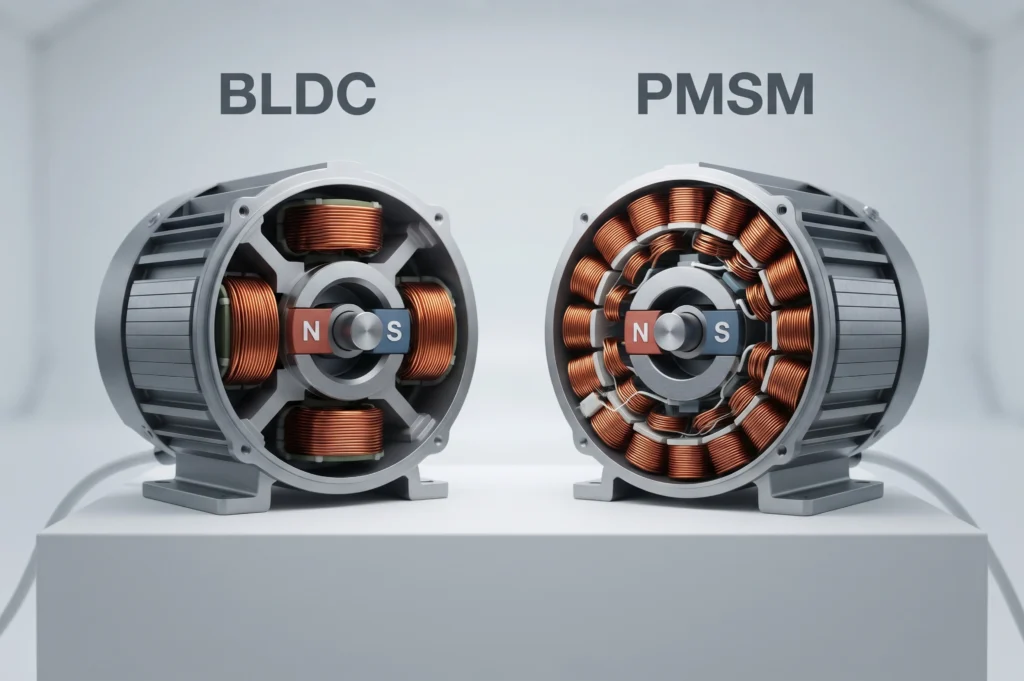
Physically, a BLDC motor and a PMSM are the same kind of machine: permanent-magnet synchronous motors. The labels describe the back-EMF shape and the intended drive. “BLDC” implies a trapezoidal back-EMF matched to six-step commutation, and “PMSM” implies a sinusoidal back-EMF matched to FOC. A mismatch costs performance. Six-step on a sinusoidal machine raises torque ripple, and FOC on a strongly trapezoidal machine leaves harmonic torque unused. Datasheets use the terms loosely, so verify by spinning the motor with another drive or by hand and scoping the line-to-line voltage.
Three constants describe a brushless DC machine electrically:
In consistent SI units, the torque constant and back-EMF constant are numerically equal. Watch whether a datasheet quotes phase or line-to-line values; mixing them introduces errors of about 1.73 times.
Illustrative example: a 24 V motor rated at 200 rpm per volt spins at roughly 4,800 rpm unloaded. With a line resistance of 0.2 ohm, its stall current would be about 120 A, far above a typical rated current. In practice, the drive’s current limit, not the motor, defines achievable peak torque.
At fixed voltage, speed falls in a near-straight line as torque rises. Datasheets mark a continuous operating zone, limited thermally, and an intermittent zone usable for short bursts. Above base speed, field weakening extends the speed range at reduced torque, creating a visible “knee.”
Losses fall into several groups:
Cogging torque exists even with no current, while commutation ripple comes from the drive. Magnet remanence falls as temperature rises, so torque per amp drops as the motor heats.For sintered NdFeB, the reversible remanence loss is typically about 0.08% to 0.12% per °C, depending on grade.
For efficiency, IEC 60034-2-1 defines loss-determination methods for line-fed machines, and IEC 60034-30-1 defines IE classes for line-operated AC motors.Most inverter-fed brushless DC motors are instead tested under IEC 60034-2-3 (converter-fed motors). Efficiency classes IE1–IE5 for variable-speed AC motors come from the technical specification IEC TS 60034-30-2, whose scope covers machines designed for sinusoidal fundamental current, such as permanent magnet synchronous machines, so six-step trapezoidal BLDC drives may fall outside it. Treat any single headline efficiency figure with caution unless the test method and operating point are stated.
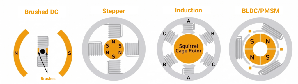
| Criterion | Motor types | Key characteristics |
|---|---|---|
| Electronics needed | Brushless DC: Yes; Brushed DC: No; Induction: Optional (line-start) or VFD; Stepper: Yes | Brushless DC requires an inverter and position information; stepper motors require a driver. |
| Efficiency | Brushless DC: High; Brushed DC: Moderate; Induction: Good at large sizes; Stepper: Low | Stepper motors draw full current at standstill unless current is reduced. |
| Lifetime | Brushless DC: Bearings/insulation; Brushed DC: Brush-limited; Induction: Bearings/insulation; Stepper: Bearings | Brushed DC motor lifetime is limited by brush wear. |
| Torque density | Brushless DC: Highest; Brushed DC: Moderate; Induction: Lower; Stepper: High at low speed only | Torque density varies with motor type and operating speed. |
| Magnets | Brushless DC: Yes; Brushed DC: Yes (PM types); Induction: None; Stepper: Yes | Permanent magnets are used in brushless DC motors and some brushed DC motors. |
| Positioning | Brushless DC: Excellent with encoder; Brushed DC: Needs encoder; Induction: Needs encoder; Stepper: Open-loop steps | Feedback improves position verification in closed-loop systems. |
Switched reluctance motors are a fifth, magnet-free option, rugged but noisy and ripple-prone. A practical decision rule:
Back-drive a brushless DC machine and it becomes a brushless DC generator, with back-EMF rising in proportion to speed. The inverter can rectify passively through its switches’ body diodes, or actively by switching all six devices synchronously for lower loss and controlled braking torque. This enables regenerative braking in EVs, e-bikes and elevators. Small wind turbines and micro-hydro units also use PM brushless generators.
The hazards come from the same physics. Regenerated energy raises the DC-link voltage, which can overshoot if the source cannot absorb it, for example with a full battery. If the inverter trips at high speed, the machine keeps generating. Once back-EMF exceeds the bus voltage, current flows uncontrolled through the diodes. Drives therefore use a brake chopper and resistor, a crowbar, or a controlled active short circuit to stay safe.
A BLDC driver (or BLDC motor driver) is the electronics that turns DC power and a command into correctly timed three-phase currents. A complete brushless DC motor drive contains:
Driver vs controller terminology. Usage varies. Strictly, a BLDC driver is often the power stage plus gate drive (sometimes integrated into a single gate-driver chip), while a BLDC controller or brushless DC motor controller adds the processor and control algorithms. In practice, “BLDC motor controller”, “bldc controller” and “drive” usually mean the complete unit, and drone engineers call the same unit an ESC.
Key BLDC driver specifications:
How Impedyme validates BLDC drivers. Impedyme tests and validates BLDC drivers and brushless DC motor controllers with its Motor Emulator.The emulator connects directly to the inverter’s three-phase terminals and electrically behaves like the motor, so no spinning machine is needed. On impedyme , the Motor Emulator is described as an FPGA-based system whose motor model updates every 90 ns (about 11.1 MHz).MotorSim Studio configures BLDC, PMSM, induction and IPM models with parameters such as resistance, inductance, back-EMF constant, torque constant and pole pairs. Programmable fault injection covers phase short circuits, open phases, sensor failures, torque disturbances and power anomalies. The BLDC motor emulator page also lists validation of Hall, encoder and sensorless strategies. Signal-level testing runs on the HIL/RCP-Box, and power-level Power Hardware in the Loop runs on CHP Series hardware with four-quadrant operation.
When evaluating motor drive inverters or MCUs, engineers often use load banks or mechanical dynos to mimic motor conditions. However, these methods have serious limitations. A brushless motor emulator offers a fundamentally higher level of fidelity, enabling precise, scalable, and reproducible testing.
| Criteria | Passive Load![]() | Active Load![]() | Motor Emulator (Impedyme) ![]() |
|---|---|---|---|
| Waveform Fidelity | Very low – fixed, unrealistic waveforms | Medium – RMS/average currents only | High – replicates back-EMF, torque ripple, phase currents |
| Dynamic Behavior | None | Limited – partial current control | Full – startup surges, braking, regenerative dynamics |
| Algorithm Validation | Not possible | Limited | Full FOC, sensorless, slew-rate, regenerative testing |
| Fault Injection | Unsafe or not possible | Very limited | Safe, controlled, and repeatable (phase faults, shorts, open lines) |
| Energy Efficiency | Very low – power wasted as heat | Medium – programmable load but still lossy | High – efficient emulation with reduced heat waste |
| Scalability | Not scalable | Limited scalability | Multi-motor emulation supported in parallel |
| Cost vs. Value | Low upfront, but limited usefulness | Higher cost, limited fidelity | Best ROI – replaces dyno and motors, saves time/resources |
At the core of every motor drive, ZCU, and inverter system are half bridge and full bridge topologies built on MOSFET, SiC, or GaN power devices. These bridges must withstand rigorous operating conditions, from high-frequency switching to regenerative braking. When the switches are gated off, the anti-parallel diodes in a full bridge behave like a full bridge rectifier, feeding motor back-EMF into the DC link. A single half bridge leg can conduct in a similar way to a half wave rectifier. Both conditions need to be validated as carefully as active switching.
With a BLDC or Brushed DC motor emulator, suppliers can validate power modules more effectively:
High-Fidelity Load Profiles: Replicates back-EMF, torque ripple, and regenerative braking typical of real motors.
Switching Performance Testing: Validate slew-rate control, dead-time optimization, and thermal cycling in half bridge and full bridge circuits.
Safe Fault Injection: Reproduce short circuits, desaturation events, and abnormal drive conditions without damaging real motors.
Scalable Multi-Bridge Testing: Emulate multiple half bridges simultaneously to validate entire ZCU modules. This enables both half bridge testing and full bridge testing under controlled and repeatable conditions.
This approach ensures robust evaluation of gate drivers, inverter stages, and power electronics under realistic operating conditions.
Use this checklist when pairing a brushless DC motor with a BLDC motor controller:
A choice that looks right on paper still has to survive start-up, overload, regeneration and faults, and that is where validation begins.
Dynamometer testing couples the motor to a load machine. It measures real shaft torque, efficiency and thermal behavior, and it remains essential for final motor characterization. It is also slow to reconfigure, mechanically hazardous at high speed, limited to the motors you physically have, and unsuitable for destructive fault cases.
Power-electronic motor emulation replaces the motor at the inverter’s three-phase terminals with a regenerative power stage driven by a real-time machine model. The emulator reproduces back-EMF, inductance, resistance, pole pairs and load torque, so the drive under test sees the currents and voltages of a real machine.Motor parameters change in software. Faults that would destroy a real motor become repeatable test cases: phase loss, shorted turns, Hall or encoder failure, demagnetization and locked rotor.
P-HIL (power hardware-in-the-loop) closes the loop with a real-time model of the machine and its mechanical load, often a whole vehicle or propeller. A battery emulator on the DC side reproduces voltage sag, state of charge and regenerative acceptance.
What to test on a BLDC drive:
Impedyme provides both sides of this bench. The Motor Emulator emulates the machine, with its FPGA motor model updating every 90 ns.The Real-Time Battery Emulator reproduces battery terminal behavior on the DC link, and PowerHIL Studio orchestrates the automated test sequences.
The Impedyme Motor Emulator is purpose-built for next-generation testing demands:
This makes the Impedyme BLDC motor emulator the best-in-class solution for MCU testing, BLDC drive development, and PHIL-based inverter validation.
A brushless DC motor is a permanent-magnet synchronous machine whose commutator has been replaced by an inverter and a rotor-position signal. That makes every brushless DC electric motor a motor-plus-drive system. Three decisions dominate its behavior: rotor topology and magnet material, six-step versus FOC commutation, and sensored versus sensorless operation. Remember that stall current usually dwarfs rated current, so the BLDC motor controller’s current limit, not the BLDC motor, sets real peak torque. Finally, a BLDC driver or brushless DC motor drive is only as good as its validation, and emulator-based and P-HIL testing let teams prove start-up, faults and regeneration before a real shaft turns.
Is a BLDC motor AC or DC?
It is both. The BLDC is supplied from DC, and its speed-torque behavior resembles a DC motor, but the windings carry alternating, switched currents produced by the inverter. Electrically it is an AC synchronous machine with an integrated DC-to-AC drive.
Can a brushless DC motor run directly on DC?
No. Connected straight to a DC source, a brushless DC motor energizes one winding path, aligns its rotor and holds there without rotating. Continuous rotation needs a controller that switches the phases in sequence using measured or estimated rotor position.
What is the difference between a BLDC driver and a BLDC controller?
Strictly, a BLDC driver is the power stage and gate drive, while a BLDC controller adds the processor running commutation and control loops. In everyday usage the terms overlap, and both often describe the complete unit that converts DC power into controlled three-phase currents.
Can a brushless DC motor be used as a generator?
Yes. When driven mechanically, a brushless DC machine produces back-EMF proportional to speed, which the inverter rectifies passively or actively. This is the basis of regenerative braking and of small wind and hydro generators, but the DC-link voltage must be managed carefully.
How long does a brushless electric motor last?
A brushless electric motor’s life is set mainly by its bearings and winding insulation, not by brushes, so it typically outlasts a comparable brushed motor by a wide margin. Operating temperature, load, vibration and sealing quality determine actual service life.
How are BLDC motor controllers tested?
BLDC motor controllers are tested on dynamometers, with motor emulators connected to the inverter terminals, and in power hardware-in-the-loop benches.Emulation allows repeatable fault injection, sensorless start-up checks and regeneration tests that would be risky or destructive on a real motor.