
Every switched-mode power supply, solar inverter, motor drive, and electric vehicle onboard charger connected to the AC grid has one thing in common: it must draw current from the grid cleanly. That responsibility falls on the power factor correction (PFC) stage — and, more specifically, on the embedded controller that governs it. The PFC controller regulates the DC bus voltage, shapes the input current to follow the grid voltage, detects faults in microseconds, and orchestrates high-frequency switching across the power stage. If that controller misbehaves, the consequences range from harmonic pollution and regulatory non-compliance to destroyed semiconductors and safety hazards.
Testing this controller thoroughly is therefore non-negotiable. But testing it against a real, energized power converter is expensive, slow, and genuinely dangerous — especially when you need to verify how the controller reacts to short circuits, open switches, grid sags, and other conditions you would never want to create deliberately on a physical bench.
This is exactly the problem that controller hardware-in-the-loop (HIL) testing solves. By connecting the real controller to a high-fidelity digital twin of the PFC converter running on an FPGA-based real-time simulator, engineering teams can validate control firmware early, inject faults safely, and automate thousands of test cases — long before the first power board is energized.
In this guide, we walk through the complete methodology for controller HIL testing of a power factor correction converter, with a focus on the totem pole topology that dominates modern high-efficiency designs. We cover why PFC controllers are hard to test, how FPGA-based real-time simulation makes nanosecond-resolution converter models possible, and how Impedyme’s CHP Series hardware and PowerHIL Studio software support the entire workflow from desktop simulation to closed-loop HIL validation.
Power factor correction converters exist to improve the power quality of electrical systems. When electronic loads draw current from the AC mains without correction, the current waveform becomes distorted and out of phase with the voltage. This wastes capacity in the distribution network, injects harmonics that disturb neighboring equipment, and violates grid codes and standards that regulate the harmonic content of line current.
A PFC front-end sits between the AC grid and the downstream DC loads. Its job is to make the equipment look, electrically, like a clean resistive load: input current in phase with input voltage, minimal harmonic distortion, and a tightly regulated DC output bus. In practice, this is achieved by a boost-type converter operating under closed-loop control, with an outer voltage loop maintaining the DC bus and an inner current loop shaping the line current to track a sinusoidal reference derived from the grid voltage.
Because PFC stages sit at the very front of the power chain, their reliability affects everything downstream. And because they interface directly with the grid, their control behavior is scrutinized by certification bodies, utilities, and end customers alike. This makes the PFC controller one of the most safety-critical and compliance-critical pieces of firmware in the entire product.
Among the many PFC topologies, the bridgeless totem pole configuration has become the design of choice for modern high-efficiency systems. By eliminating the lossy input diode bridge and replacing it with actively switched devices, the totem pole PFC reduces conduction losses dramatically. Wide-bandgap semiconductors — silicon carbide and gallium nitride MOSFETs — have made continuous conduction mode totem pole PFC practical at medium and high power levels, delivering peak efficiencies that legacy topologies simply cannot match.
The totem pole structure consists of two half-bridge legs forming a full bridge: one fast-switching leg operating at the PWM frequency, and one slow leg switching at the line frequency to steer current during positive and negative half-cycles. Combined with a line inductor at the input and a bulk capacitor at the output, this compact arrangement supports bidirectional power transfer — a decisive advantage for EV onboard chargers that must support vehicle-to-grid operation, and for energy storage systems that both charge and discharge.
But the topology’s efficiency comes at the cost of control complexity. A totem pole PFC controller must handle:
Every one of these functions must be verified — not just under nominal conditions, but across the full envelope of grid conditions, load transients, and fault scenarios the product will ever encounter.
The bridgeless totem-pole PFC converter architecture consists of a full-bridge switching structure split into two functional legs, an AC line inductor, and a DC output smoothing capacitor. Eliminating the front-end diode rectifier reduces the conduction path to a single high-frequency switch and one low-frequency switch at any moment, maximizing electrical efficiency.
The power conversion topology is formed by two half-bridge legs connected in parallel across the DC bus output:
During the positive half-cycle of the AC mains voltage, the lower switch of the low-frequency leg remains continuously closed, grounding the AC neutral line to the negative DC return bus. The lower switch of the high-frequency leg acts as the primary boost switch, storing energy in the AC inductor when turned on. When this active switch turns off, the upper high-frequency switch conducts synchronously, transferring the inductor energy into the DC output capacitor and load.
During the negative AC half-cycle, the switch roles reverse: the upper switch of the low-frequency leg grounds the line terminal to the negative bus, while the upper switch of the high-frequency leg operates as the primary boost control element.
Regulating the bridgeless totem-pole PFC converter requires a cascaded control architecture implemented within the firmware of the embedded digital signal processor or microcontroller:
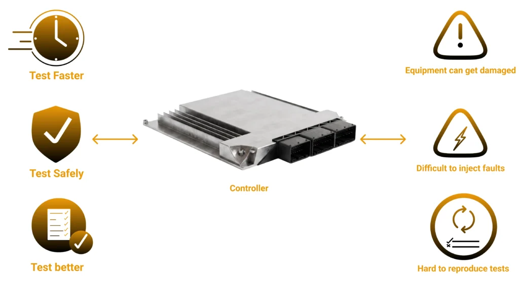
Controller hardware-in-the-loop testing inverts the traditional approach. Instead of connecting the controller to a real power converter, you connect it to a digital twin of the converter — a real-time simulation model executing on dedicated test hardware fast enough that, from the controller’s perspective, it is indistinguishable from the physical plant.
The controller under test runs its actual production firmware on its actual silicon. It generates real PWM signals, reads real analog feedback voltages, and responds to real digital I/O — but the “converter” on the other side of those signals is a mathematical model running on an FPGA. The simulator captures the controller’s PWM outputs, computes the converter’s electrical response with nanosecond resolution, and drives the controller’s sense inputs with correctly scaled analog signals representing inductor current, bus voltage, and grid voltage.
This closed-loop arrangement delivers three decisive advantages:
Test faster, earlier, and with less hardware dependence. Controller validation no longer waits for power hardware. Firmware teams can begin closed-loop testing as soon as the control board exists — or even earlier, using rapid control prototyping. Design iterations that once took weeks compress into hours, because “rebuilding the plant” means updating a simulation model, not soldering a new board.
Inject faults safely and repeatably. Short circuits, open switches, sensor failures, grid collapses, harmonic distortion, frequency excursions — all can be injected into the digital twin at precisely defined instants, with perfect repeatability, and with zero risk to hardware or people. The controller’s protection logic can finally be tested exhaustively rather than anecdotally.
Achieve high coverage through automation. Because the plant is simulated, entire test campaigns can run unattended. Parameter sweeps across grid voltages, load steps, component tolerances, and fault timings execute automatically, with pass/fail criteria evaluated programmatically and full waveform data logged for every run. Regression testing after every firmware change becomes routine instead of aspirational.
Not every real-time simulator can test a PFC controller. The defining challenge is switching frequency.
A totem pole PFC built on wide-bandgap devices may switch at several hundred kilohertz. To capture the controller’s PWM edges accurately and reproduce the converter’s switching dynamics faithfully, the simulation must resolve events far faster than the switching period itself. CPU-based real-time simulation, with time steps in the tens of microseconds, is orders of magnitude too slow — an entire PWM cycle, or several, would pass between simulation updates, and the model would effectively see averaged, information-destroying snapshots of the controller’s behavior.
The answer is FPGA-based simulation. By implementing the converter model directly in FPGA fabric, simulation time steps shrink to just a few nanoseconds. At that resolution the simulator can:
Achieving nanosecond time steps requires careful model engineering. Practical FPGA converter models use switch-level linear representations of the power devices — capturing switching dynamics and fault behavior without the computational burden of fully detailed physics-based semiconductor models — and fixed-point arithmetic to optimize execution latency and FPGA resource usage. PWM sub-cycle averaging techniques preserve the effect of switching edges that fall between simulation steps, ensuring the emulated currents and voltages remain accurate even at extreme switching frequencies.
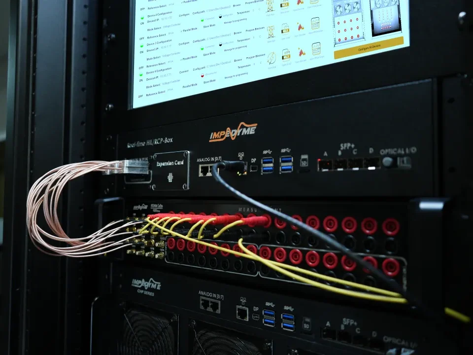
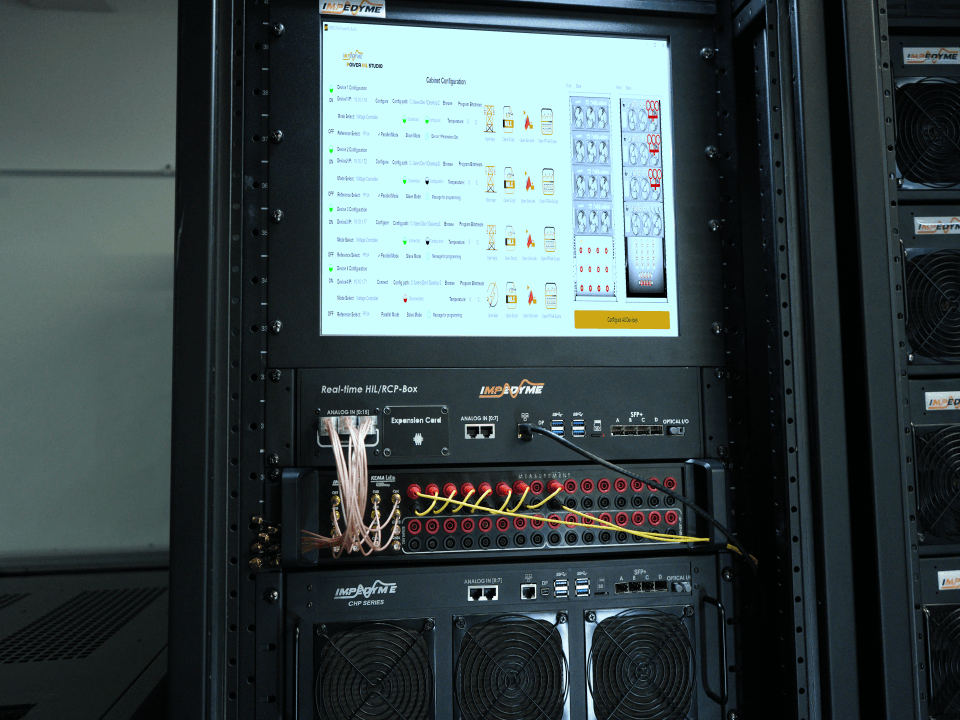
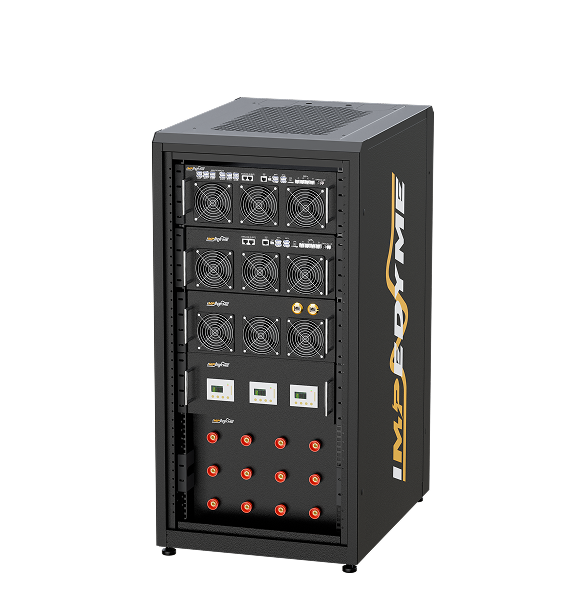
This is precisely the class of simulation the Impedyme CHP Series was engineered for. The CHP platform combines a real-time processor for system-level simulation with FPGA resources dedicated to ultra-fast power electronics models, along with the high-speed digital and analog I/O needed to close the loop with an external controller at full signal fidelity.
Simulating a high-frequency switching power converter in real time introduces computational demands that differ significantly from those of conventional real-time power grid or mechanical systems.
Standard real-time execution engines running on traditional central processing units typically operate with fixed integration time steps between 10 microseconds and 50 microseconds. While this resolution is sufficient for tracking low-frequency power grid dynamics or electromechanical drives, it is inadequate for high-frequency switching converters. At a switching frequency of 100 kHz, the complete switching period is 10 microseconds. Executing a simulation model at a 10-microsecond step size yields only one state update per switching period, introducing severe pulse-width modulation quantization errors, distorted duty-cycle measurements, and artificial numerical instabilities in the control loop.
Accurately capturing high-frequency switching behavior requires sub-microsecond execution resolution. Engineering guidelines recommend that a real-time simulator run at least twenty times faster than the target converter’s switching frequency. For converters operating at hundreds of kilohertz, the real-time simulation step must be reduced to the nanosecond domain.
When an external physical controller sends high-frequency pulse-width modulation gate signals to a discrete-time simulator, the gate transitions rarely align with discrete simulation step boundaries. If the simulator samples these inputs asynchronously at coarse intervals, duty cycles are quantized into coarse discrete steps. This quantization causes artificial current oscillations, phase jitter, and false current spikes that destabilize the controller under test.
To resolve these errors without requiring unachievable sub-nanosecond simulation time steps, Field Programmable Gate Array (FPGA) logic engines employ sub-cycle PWM averaging:
Continuous, highly non-linear semiconductor models that account for complex physical phenomena—such as non-linear junction capacitances and continuous i-v curves—require iterative numerical solvers. Iterative solvers have variable execution times, making them unsuitable for deterministic real-time execution where missed time steps cause simulation failure.
To ensure deterministic nanosecond execution on FPGA hardware, the totem-pole PFC topology is implemented using switch-linear fixed-point mathematical representations. In a switch-linear framework, power switches and diodes are modeled as state-dependent linear circuit elements that transition between discrete conduction states. The state equations governing inductor currents and capacitor voltages are formulated as fixed-point matrix equations. Fixed-point arithmetic optimizes digital logic resource utilization, minimizes latency, and guarantees that the entire power stage mathematical model updates within a fixed clock cycle.
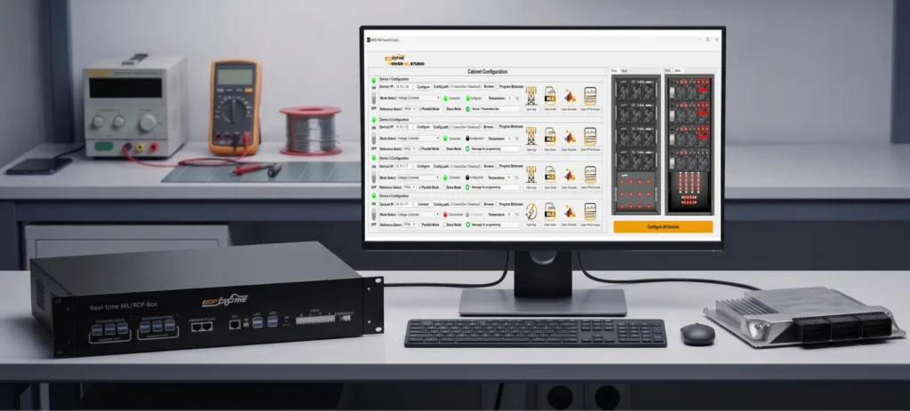
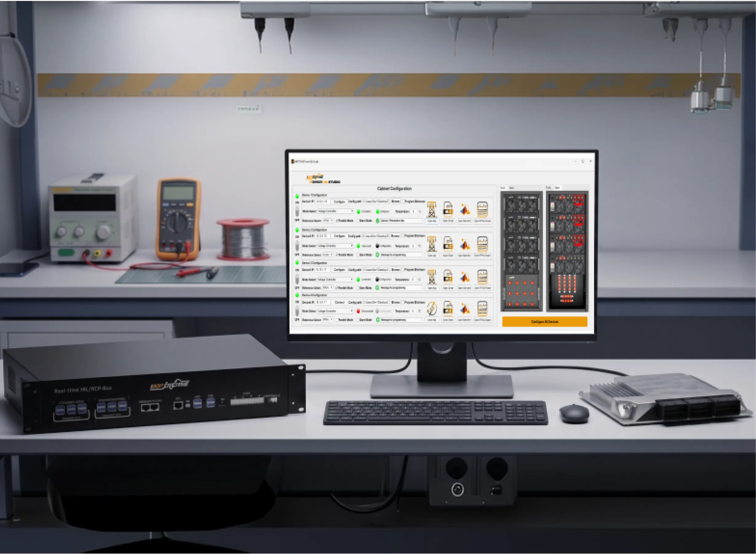
A representative controller HIL setup for PFC testing consists of four elements:
The controller connects to the simulator through appropriate cabling and interface hardware that maps its PWM outputs, analog sense inputs, and digital I/O to the simulator’s high-speed interfaces. Impedyme’s signal conditioning and breakout options streamline this connection, matching voltage levels and pinouts between common controller development boards and the CHP platform. For larger programs, the same components scale from a desktop setup into full rack-based test systems integrating signal conditioning, fault insertion units, and breakout panels for connectivity with additional external hardware.
Inside PowerHIL Studio, the test application is organized around two main components: an interactive instrument panel — virtual dashboards for adjusting references, toggling faults, and monitoring waveforms in real time — and the power converter system model itself, comprising the totem pole power stage and the voltage and current control structure.
One of the most valuable aspects of a well-structured HIL methodology is that it supports iterative, progressive validation. Rather than jumping straight to closed-loop testing with the physical controller, teams move through a sequence of simulation modes, each building confidence and each validated against the last.
The journey begins entirely on the development computer. Both the totem pole PFC converter and its controller run in offline simulation, with the converter represented at high fidelity — including detailed, non-linear switching device models. This desktop model is far too computationally heavy for real-time execution, but that is not its purpose. Its purpose is truth.
Running this model and archiving its simulation results establishes a golden reference baseline: the definitive record of how the converter and controller should behave. Every subsequent design stage — the FPGA-optimized real-time model, and ultimately the closed-loop HIL results with the physical controller — is compared against this baseline to confirm consistency and accuracy as the design progresses.
Testing a controller that switches at hundreds of kilohertz requires a converter model suitable for nanosecond-precision real-time simulation. One path is to adapt the golden reference model by hand — incorporating PWM sub-cycle averaging, explicit switching logic, and I/O connectivity. A faster path is to start from a pre-built, FPGA-optimized converter model.
Impedyme provides ready-made FPGA power converter models covering established power electronics topologies, including the totem pole PFC. The totem pole example includes:
From this model, an automated deployment workflow generates target-optimized FPGA logic, maps the model’s inputs and outputs to the CHP Series’ physical interfaces, and packages the result as a reusable block ready to drop into the system-level real-time application. Teams that run this flow regularly can script it end-to-end, turning FPGA regeneration into a single automated step in their build pipeline.
Before connecting the physical controller, the deployed FPGA model is verified in real-time model-in-the-loop mode: the converter runs on the FPGA while a simulated copy of the controller runs on the real-time processor. This closed loop — entirely inside the simulator — confirms that the FPGA design was generated and deployed correctly.
The results are compared against the golden reference baseline. Some differences are expected and understood: the desktop model uses detailed device physics, while the real-time model uses a switch-level fixed-point representation. The comparison confirms that these differences remain within acceptable bounds, and that the real-time plant reproduces the essential dynamics the controller will interact with.
This mode is also where the high-speed logging infrastructure earns its keep. Frame-based capture — for example, streaming frames of hundreds of samples at intervals of tens of microseconds — lets engineers reconstruct the original FPGA-resolution waveforms in the data inspection tools, examining voltage and current switching dynamics in fine detail. The simulator’s analog outputs can simultaneously drive an oscilloscope, giving hardware engineers the familiar experience of probing “the converter” with lab instruments.
Now the physical controller enters the loop. The simulated controller is disabled, the device under test is connected through the interface harness, and the application is rebuilt and launched in HIL mode. The real microcontroller, running real firmware, now closes the loop around the FPGA-based digital twin.
The first and most fundamental check is equivalence: do the output waveforms produced under external controller operation match those from the real-time model-in-the-loop run? When they do — when the physical controller produces waveforms identical to its simulated counterpart — the team has powerful evidence that the control implementation faithfully realizes the control design, and that the entire signal chain between controller and simulator is correctly configured.
From there, dynamic testing begins. Typical scenarios include:
Every one of these tests is scripted, repeatable, and safe. A short-circuit test that would destroy a physical prototype becomes a routine regression case that runs on every firmware commit.
EV onboard chargers. The totem pole PFC is the front end of choice for onboard chargers, and its bidirectional capability underpins vehicle-to-grid functionality. Automotive validation demands enormous test coverage across grid conditions worldwide, and functional safety processes require documented, reproducible fault-response evidence — a natural fit for automated HIL campaigns on Impedyme systems.
Server and telecom power supplies. Data center power supplies push efficiency targets that only totem pole architectures reach, at power densities that leave no margin for control error. HIL regression testing protects firmware quality across the rapid product cycles this market demands.
Solar inverters and energy storage. Grid-tied converters face stringent grid-code compliance requirements covering harmonics, ride-through, and anti-islanding behavior. Testing these behaviors against a simulated grid is dramatically faster and safer than arranging real grid-disturbance testing.
Motor drives and industrial power. Active front ends in motor drives perform the same power factor correction function and inherit the same validation challenges, particularly around regeneration and fault handling.
Across all of these, the shared theme is the same: the controller is the product, and controller HIL testing is the fastest, safest route to proving it.
C-HIL testing enables complete evaluation of controller dynamic performance and safety functions under transient and fault conditions without risking hardware damage.
To verify the controller’s transient response during real-time C-HIL execution, dynamic operational step changes are commanded through the real-time target interface:
Testing protection logic on physical power converters carries high risk, as software errors can lead to component destruction. In the Impedyme C-HIL environment, electrical faults are introduced safely into the FPGA model during real-time execution:
Teams that get the most from controller HIL testing tend to follow a consistent set of practices:
Anchor everything to a golden reference. Maintain the high-fidelity desktop model as the single source of truth, and version its baseline results alongside the firmware. Every model simplification and every deployment step is validated against it.
Understand your model’s fidelity boundaries. Know exactly which behaviors the switch-level real-time model captures and which it abstracts. Document expected differences from the golden reference so genuine regressions are never mistaken for known modeling deltas — and vice versa.
Verify the deployment before blaming the firmware. Real-time model-in-the-loop runs, executed before every HIL campaign, isolate simulator-side issues from controller-side issues. When a HIL test fails, you want certainty about which side of the loop to investigate.
Automate from day one. Script the FPGA build flow, the test execution, and the results evaluation. Manual HIL testing captures a fraction of the value; automated HIL testing turns the simulator into a continuously running quality gate.
Log at full resolution. Use frame-based FPGA logging to capture switching-level detail for every test run. When an intermittent anomaly appears once in ten thousand automated runs, the waveform record is the difference between a fix and a mystery.
Treat fault scenarios as first-class test cases. Build a fault catalog — device shorts and opens, sensor failures, grid events — and run it as part of standard regression, not as an occasional special exercise.
Plan for scale. A desktop HIL setup is ideal for a firmware engineer’s daily work; rack-integrated systems with fault insertion units and breakout panels serve team-level validation and pre-compliance campaigns. Choosing a platform that spans both, as the Impedyme CHP Series does, avoids painful mid-program migrations.
Impedyme’s controller HIL solution brings together every element of the workflow described above:
The same platform extends naturally beyond PFC: the CHP Series and Studio suite support DC-DC converter testing, motor drive HIL with MotorSim Studio, battery system validation with BatterySim Studio, and grid-interactive converter testing with GridSim Studio — so an investment in PFC controller HIL becomes the foundation of a lab-wide validation capability.
Why does PFC controller testing require an FPGA-based simulator?
Modern totem pole PFC converters switch at hundreds of kilohertz. Capturing PWM edges and reproducing switching dynamics at those frequencies requires simulation time steps of just a few nanoseconds — far beyond what CPU-based real-time simulation can achieve. FPGA execution delivers that resolution while maintaining the low loop latency the controller expects.
Can HIL testing replace testing on the real power converter?
No — and it shouldn’t. HIL testing front-loads validation so that controller defects are found early, safely, and cheaply. Final verification on physical power hardware remains essential, but it becomes a confirmation exercise on an already-proven controller rather than a discovery process for firmware bugs.
How are faults like short circuits tested in a HIL environment?
The FPGA converter model includes built-in fault modes — such as short-circuit and open-circuit conditions on individual switching devices — that can be activated at precisely defined moments during a simulation run. The controller experiences the resulting electrical transients exactly as it would on real hardware, and its detection and protection response can be evaluated repeatedly with zero risk of damage.
What applications benefit most from PFC controller HIL testing?
EV onboard chargers, server and telecom power supplies, solar inverters, energy storage systems, and industrial motor drives with active front ends — any product where a grid-connected converter’s controller must be validated across wide operating envelopes, strict compliance requirements, and comprehensive fault scenarios.
What signals connect the controller to the HIL simulator?
The controller’s PWM outputs drive the simulated converter’s switching logic through high-speed digital inputs, while the simulator’s scaled analog outputs feed the controller’s current, voltage, and power sense inputs. Additional digital I/O carries enable signals, fault flags, and relay commands. Interface and signal-conditioning hardware matches voltage levels and connector pinouts between the controller board and the simulator.