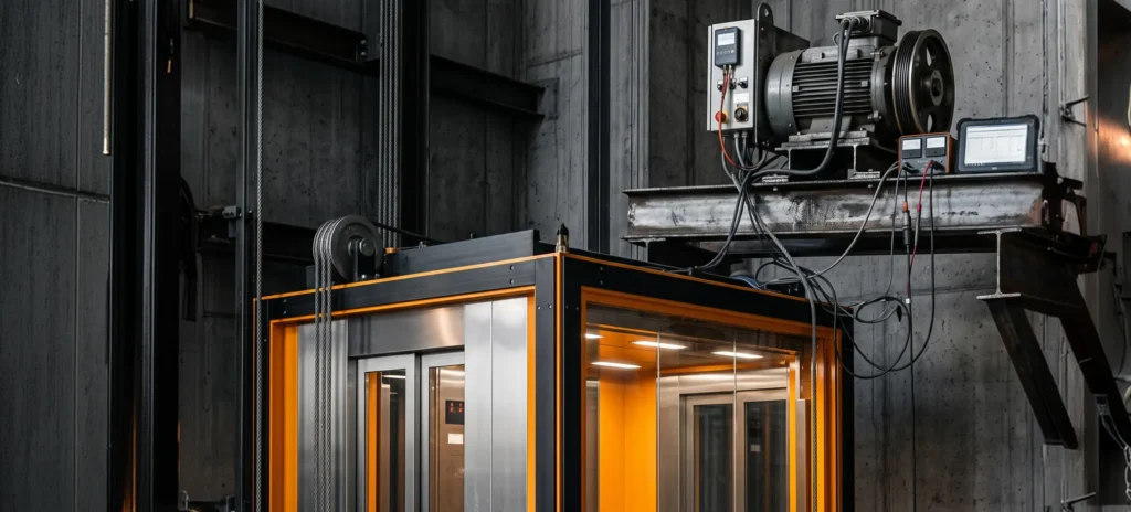
Elevator motor drive is the power-electronics and control system that converts a fixed building supply into the precisely shaped, variable-frequency power an elevator machine needs to move a car smoothly, stop it level with the floor, and recover energy on the way down. In other words, it is the component that turns a motor into a ride-quality system. This page explains what an elevator motor drive is, how the major drive families evolved, how a drive works from call registration to brake set, how the physics of the counterweight makes four-quadrant operation mandatory, and — because we build the real-time test systems that elevator drive teams use — how a rigorous elevator motor drive test program validates all of it on the bench.
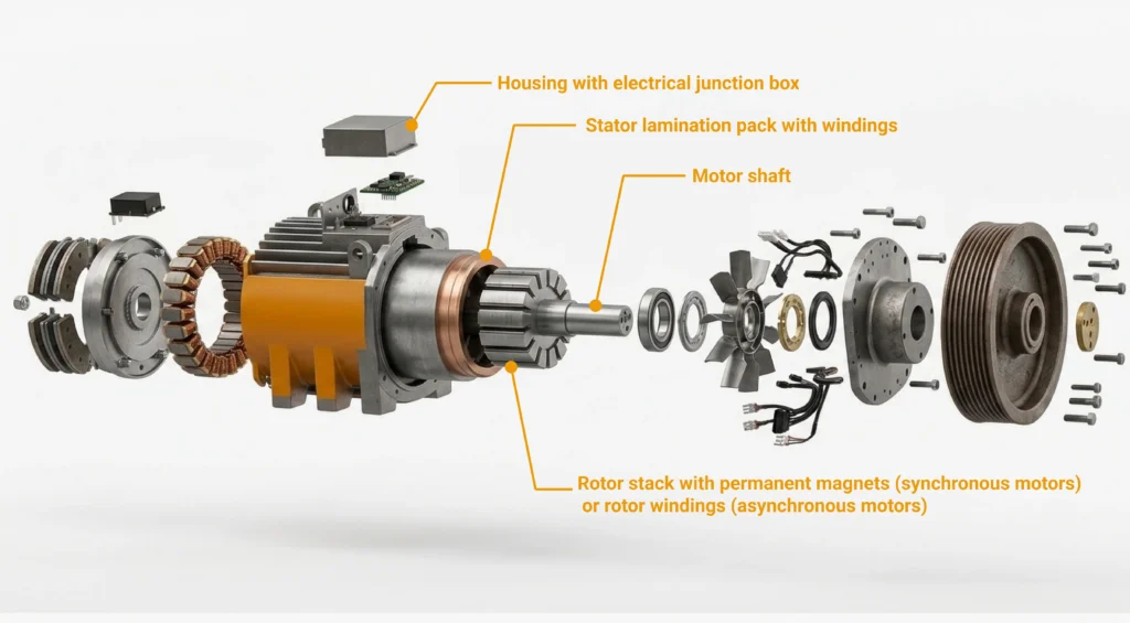
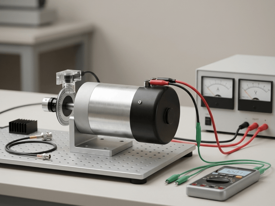
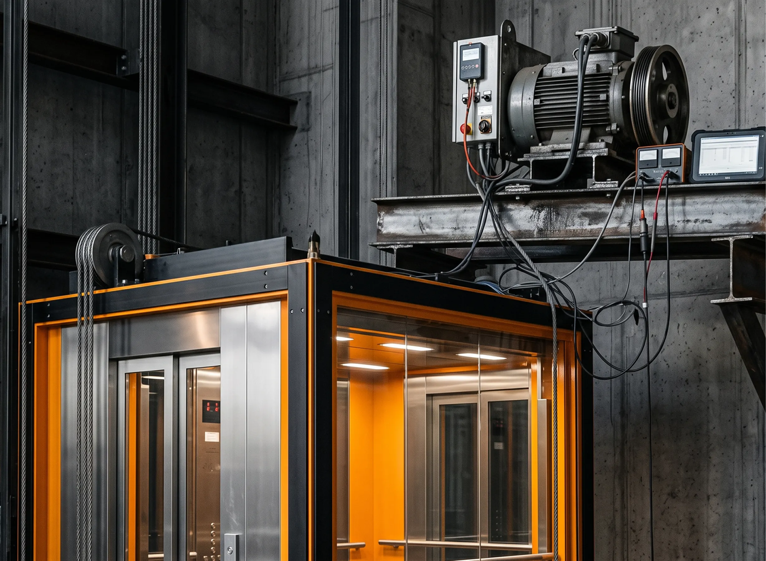
A quick grounding first. An elevator is a vertical transportation system: a car (the cab passengers ride in) suspended by steel ropes or belts, guided by rails in a shaft, and driven by a machine at the top of (or beside) the hoistway. An elevator motor is the electric machine in that drive train — historically a geared induction motor, today most often a gearless permanent-magnet synchronous machine — that turns a sheave (a grooved drive wheel) to raise and lower the ropes. On its own, a motor only spins. It is the drive that decides how fast, how smoothly, in which direction, and with how much torque — and that is why the drive, not the motor, defines the passenger experience.
An elevator motor drive is a variable-frequency power converter with an elevator-specific control layer wrapped around it. At the power level, nearly all modern drives share the same three-stage architecture, described here in plain language with no formulas.
First, a rectifier takes the building’s fixed-voltage, fixed-frequency AC supply and converts it to DC. In a simple drive this is a passive diode bridge; in a regenerative drive it is an active front end that can also push energy back to the grid.
Second, that DC feeds a DC bus — effectively a reservoir of electrical energy held on a bank of capacitors at a roughly constant voltage. The bus is the shared “trading floor” where energy flows in from the grid and out to the motor, or the reverse when the elevator regenerates.
Third, an inverter — a set of fast electronic switches (typically IGBTs) — chops the DC bus into precisely timed pulses that synthesize AC of whatever voltage and frequency the motor needs at that instant. By continuously varying frequency and voltage, the inverter sets motor speed and torque moment to moment. This is the stage that actually shapes the ride.
Around this power core sits the control system: a profile generator that decides the ideal motion, closed-loop regulators that force the machine to follow it, and the interfaces to encoders, brakes, load weighers, and the elevator controller.
Passengers do not feel speed; they feel changes in speed, and even more acutely the rate of change of acceleration, known as jerk. A well-tuned elevator motor drive generates a smooth motion profile with rounded transitions — an “S-curve” or S-ramp — rather than abrupt steps. The car eases into acceleration, holds a constant cruising velocity, eases into deceleration, and settles onto the floor.
Comfortable passenger elevators are typically commissioned to peak accelerations on the order of 0.9–1.5 m/s² and jerk values on the order of 1.0–2.0 m/s³, with lower numbers giving a gentler ride and higher numbers giving faster trips. (Ride-quality metrics of this kind are the subject of dedicated industry measurement practice; exact comfort targets vary by market and building class.) Older systems and some drives approach the final stop with a low-speed creep phase before landing; modern drives increasingly use direct-to-floor (distance-to-go) landing that decelerates straight onto the level without a creep segment, saving flight time while still arriving smoothly.
Leveling accuracy — how closely the car floor lines up with the landing sill — is a headline quality metric. Good systems hold leveling to within a few millimeters regardless of load, which matters both for the “no trip hazard” passenger experience and for code compliance.
To follow a motion profile precisely, an elevator motor drive must know where the rotor is and how fast it is turning. That feedback comes from an encoder mounted on the machine, and the encoder interface is one of the first compatibility questions in any elevator motor drive specification.
High-resolution feedback (often via digital serial protocols) is what makes silky low-speed control and accurate leveling possible. Sensorless (encoderless) control — estimating position from electrical measurements — is common in general-purpose drives and useful as a fallback, but for the ride quality, holding torque at zero speed, and leveling precision an elevator demands, a genuine encoder is the norm on traction machines. Feedback integrity is therefore a safety concern as much as a performance one: an elevator motor drive must detect a lost or corrupted signal and react safely rather than command a runaway — a response that is far easier to prove on a bench, where a 驱动电机模拟器 can drop, glitch, or corrupt the feedback signal on command, than on a live machine.
This is where an elevator motor drive differs fundamentally from most motor applications, and where a good understanding pays off. Every traction elevator has a counterweight — a stack of steel or iron running on its own rails, connected to the car by the hoist ropes over the drive sheave. The counterweight is sized to balance the car plus a fraction of the rated passenger load. That fraction, the overbalance 率/限 balance ratio, is conventionally set so the counterweight equals the empty car weight plus roughly 40–50% of rated capacity — in other words, the system is mechanically balanced when the car is about half full.
The consequence is profound: the motor rarely lifts the “whole” load. It only ever has to handle the imbalance between car-side and counterweight-side. And because the imbalance can point either way, the machine spends its life moving in all four combinations of direction and torque. Mapping them:
| Car condition | Direction | Heavier side | Machine role |
|---|---|---|---|
| Full (above balance) | Up | Car side | Motoring (drive delivers energy) |
| Full (above balance) | Down | Car side | Regenerating (load drives the machine) |
| Empty (below balance) | Up | Counterweight | Regenerating (counterweight drives the machine) |
| Empty (below balance) | Down | Counterweight | Motoring (drive pulls car down) |
Two of these four everyday cases are regenerative: a full car descending and an empty car ascending both have gravity doing the work, so the machine acts as a generator and the drive must absorb the returned energy. This is why four-quadrant operation — the ability to deliver or absorb torque in either direction of rotation — is not a premium feature on an elevator drive; it is mandatory. A drive that could only motor would have no way to control an overhauling load, and the car would accelerate uncontrollably under gravity. Handling that returned energy — burning it in a resistor or sending it back to the building — is the subject of a later section, but the requirement is born right here in the counterweight geometry. Understanding the quadrant map is the key to understanding everything else about elevator drives.
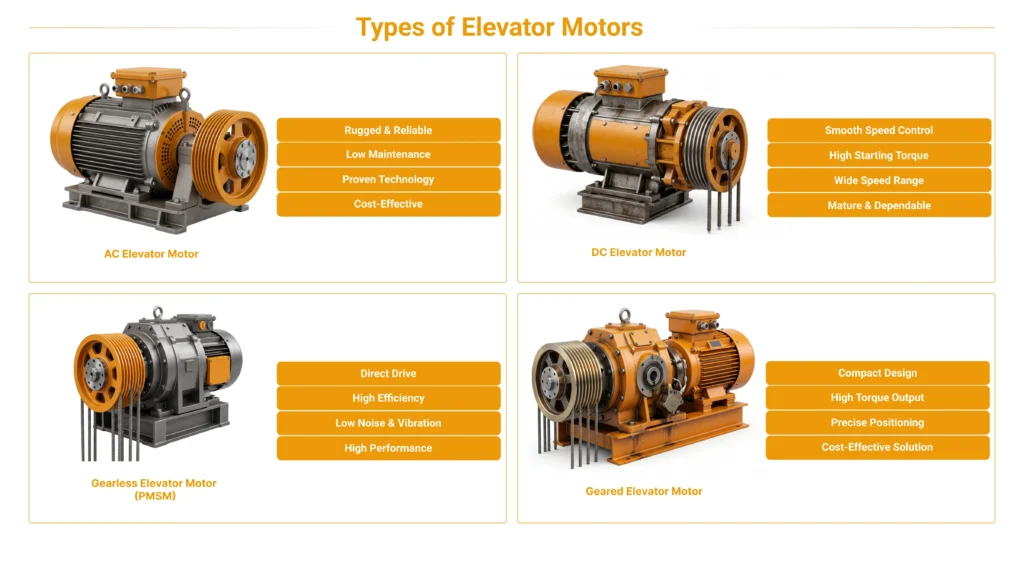
Elevator motor drive technology spans more than a century, and older families are still in service, still being maintained, and still being modernized. A complete picture of elevator motor drive systems requires covering all of them.
AC two-speed (AC-2), geared. The oldest and simplest AC approach uses a pole-changing induction motor with two fixed speeds — a high speed for travel and a low speed for approach — through a worm-gear reducer. Control is essentially on/off between the two windings, so ride quality and leveling are crude by modern standards. It is inexpensive and robust, which is why it lingered in low-rise, low-traffic buildings, but it is obsolete for new installations.
DC drives — Ward Leonard (motor-generator) and thyristor/SCR. For decades, high-performance elevators used DC hoist motors because DC gave smooth, continuously variable speed long before power electronics could do it with AC. The classic Ward Leonard system used a motor-generator set — an AC motor spinning a DC generator whose field was varied to control the elevator motor — giving excellent control at the cost of large, spinning, energy-hungry, maintenance-heavy equipment. Later static DC drives replaced the M-G set with thyristor/SCR converters, keeping the DC machine but controlling it electronically. Both are legacy technologies today, and DC-to-AC modernization is a large part of the retrofit market.
AC variable voltage (ACVV). An intermediate step controlled the voltage to an AC induction motor (via SCRs) while frequency stayed fixed, often with a feedback loop for smoother control than two-speed. It improved comfort but was inefficient (it dissipated slip energy as heat) and has been superseded.
AC variable voltage, variable frequency (VVVF) — the modern default. By controlling both voltage and frequency, VVVF drives give an induction motor smooth, continuous, fully controllable speed from standstill to top speed with efficient operation and precise leveling. VVVF is now the default for geared traction machines and is the technology base on which every modern elevator motor drive is built.
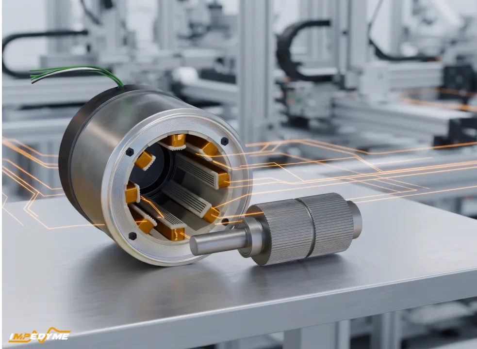
PMSM gearless drives. The biggest architectural shift was the gearless permanent-magnet synchronous machine (PMSM) driven by a VVVF drive with vector control. Eliminating the gearbox removes its losses, noise, and maintenance; the permanent-magnet rotor is highly efficient and compact enough to sit in the hoistway rather than a dedicated machine room. This is the enabling technology of the machine-room-less (MRL) elevator and is the dominant choice for new mid-rise and high-rise passenger installations.
Hydraulic and VVVF (inverter-driven) hydraulic. Hydraulic elevators raise the car with a piston driven by an oil pump, typically for low-rise buildings with modest speed needs. Traditional systems ran the pump motor across the line and threw away energy in valves, with rough starts and poor efficiency. Inverter-driven / VVVF hydraulic systems add a variable-frequency drive on the pump motor to ramp flow smoothly, improve leveling and comfort, cut energy use, and reduce oil heating — a significant modernization even within the hydraulic category.
Screw drive elevators. In screw (spindle) drives, the car rides on a large rotating (or fixed) threaded shaft, driven by a motor through a nut. They are niche — common in home elevators and short-travel accessibility lifts — valued for a small footprint and not needing a deep pit or overhead, at the cost of speed and travel.
Emerging: synchronous reluctance and linear/ropeless. Synchronous reluctance (and permanent-magnet-assisted reluctance) machines are drawing interest as a way to get PMSM-like efficiency with reduced or no rare-earth magnets. At the frontier, linear-motor “ropeless” systems drive the car directly with a linear motor and no hoist ropes, enabling multiple cars per shaft and even horizontal movement; these remain early-stage and specialized rather than mainstream.
| Drive type & typical machine | Speed control, efficiency & maintenance | Typical application & status today |
|---|---|---|
| AC two-speed (AC-2) — geared induction, two windings | Two fixed speed steps; low efficiency; moderate maintenance | Older low-rise and freight cars — obsolete for new installations |
| DC — Ward Leonard — DC machine plus motor-generator set | Excellent, continuous control; low efficiency (idling M-G set); high maintenance | Legacy mid- and high-rise — legacy technology, prime retrofit target |
| DC — thyristor / SCR — DC machine with static converter | Very good control; moderate efficiency; moderate maintenance | Legacy high-performance installations — legacy technology, prime retrofit target |
| AC variable voltage (ACVV) — geared induction | Good, slip-controlled; low efficiency (slip losses); moderate maintenance | Older mid-rise — superseded |
| VVVF (geared) — geared induction | Excellent control; high efficiency; low-to-moderate maintenance | Low- and mid-rise new builds and retrofits — current standard |
| VVVF gearless PMSM — gearless permanent-magnet synchronous machine | Excellent control; very high efficiency; low maintenance | Mid- and high-rise, machine-room-less — dominant for new builds |
| VVVF hydraulic — submersible / pump induction motor | Good control; markedly better efficiency than valve control; moderate maintenance | Low-rise and freight — current standard within hydraulic |
| Screw drive — screw / spindle motor | Moderate control; moderate efficiency; low-to-moderate maintenance | Home lifts and accessibility — niche |
| Synchronous reluctance — SynRM or PM-assisted | Excellent control; high efficiency; low maintenance | Emerging traction applications — emerging |
| Linear / ropeless — linear motor | Excellent control; efficiency and maintenance not yet established | Ultra-high-rise concepts — experimental |
Follow a single trip from the moment a passenger presses a button, and the drive’s job becomes clear. The elevator controller handles dispatching and doors; the drive handles motion.
Conceptually, all of this is governed by a nested control-loop hierarchy. The outermost loop cares about position (where the car is and where it must land). Inside it, a velocity/speed loop makes the car follow the commanded profile. Innermost and fastest is the current (torque) loop, which controls the motor’s magnetic state and the current the inverter delivers. Each inner loop runs faster than the one outside it. The inverter power stage is the muscle that executes whatever the current loop asks, in every phase from start to stop.
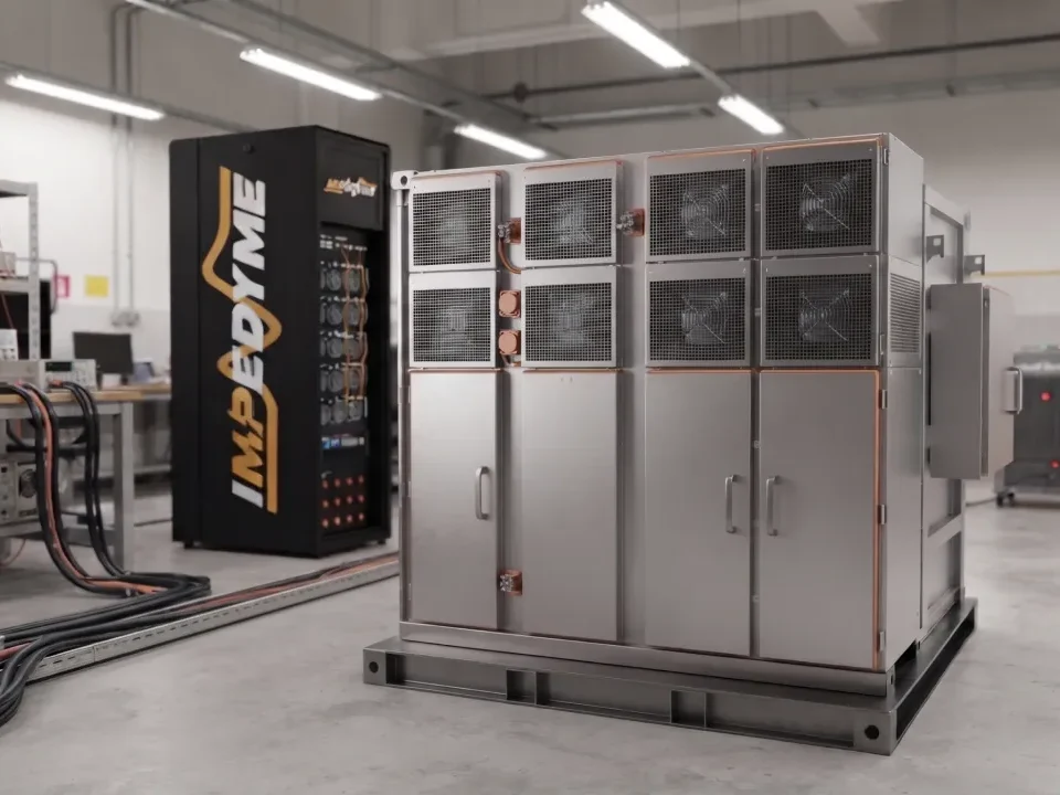
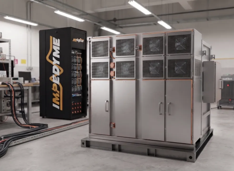
An elevator motor drive test, done properly, has to exercise the drive across every load case, every fault, and every rescue scenario it will meet in decades of service — and most of those cases are unsafe, slow, or impossible to stage on a real hoistway. This is exactly what we do: we build the real-time test systems that let elevator drive teams run a full elevator motor drive test program on the bench — the machine, ropes, car, counterweight, and grid all emulated in real time — before the drive ever enters a shaft.
In controller hardware-in-the-loop, the drive’s real control hardware and firmware run against a simulated elevator machine and mechanical system. The control board thinks it is connected to a real gearless machine, encoder, brake, and car; in fact it is talking to a real-time model. This lets teams validate the speed-profile and jerk-limiting logic, leveling accuracy, closed-loop vector control tuning, encoder handling, brake sequencing, and the drive’s state-machine logic at full firmware fidelity — with no power stage, no weights, and no shaft. Because it needs only the control electronics, it fits very early in the development cycle, where defects are cheapest to fix.
In power hardware-in-the-loop, the physical inverter runs at real voltage and current into an emulated elevator machine that electronically sinks and sources real power. Now the tests that matter for the power stage become routine: regenerative descent, four-quadrant transitions, DC-bus behavior under regeneration, and the choice between braking-resistor dissipation and line regeneration — all exercised without a single weight, shaft, or hoistway. Full-torque and overload conditions are available on demand and are repeatable to the millisecond, so a marginal thermal or bus-voltage behavior can be reproduced exactly, run after run.
The same bench can emulate the traction machine across a whole product line — geared induction, gearless PMSM, and reluctance machines — so one setup validates many drive variants. It also emulates the mechanical load: car mass, counterweight balance ratio, rope elasticity and stretch, sheave inertia, friction, and the full travel profile. Instead of physically loading a car with test weights and running it up a building, engineers sweep load cases in software — empty, balanced, full, and overloaded — and change the balance ratio or rope stiffness in seconds. Coverage that would take days in a hoistway takes minutes on the bench.
Because everything is emulated, faults that are dangerous or destructive in the field become safe, repeatable test cases: encoder loss and corruption, phase loss, brake failure and slip, overspeed, IGBT fault, and overtemperature. On the supply side we inject grid disturbances — sags, swells, imbalance, harmonics, brownout, and full outage. And we validate automatic rescue device (ARD) and battery-backup operation, including the emulated backup source, so the drive’s behavior on loss of mains — bringing the car to the nearest floor and opening the doors — is proven without staging a real power failure. Every case is repeatable, safe, and reproducible as evidence.
Test campaigns map directly to the standards elevator drives must satisfy: EN 81-20 and EN 81-50, ASME A17.1/CSA B44, and the drive-level functional-safety and EMC standards IEC 61800-5-2 and IEC 61800-3. Automated regression suites re-run the entire case library on every firmware release, and results are logged and timestamped so they can serve as certification and audit evidence rather than one-off screenshots.
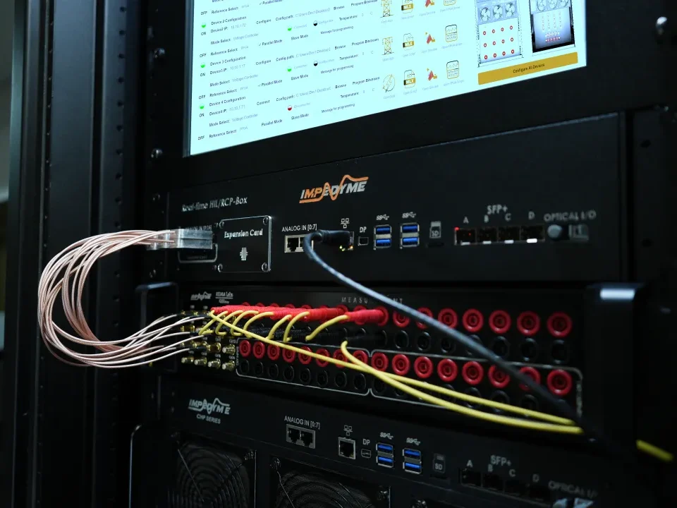
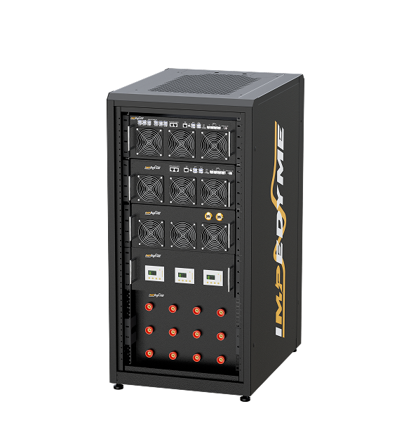
A representative bench combines our CHP Series hardware platform as the real-time core; PowerHIL Studio, for power hardware-in-the-loop orchestration; MotorSim Studio for the traction-machine and mechanical models; GridSim Studio for the building-supply and disturbance side; the 实时 电池仿真器 for ARD and battery-backup testing; FPGA Scope for signal-level visibility into fast switching and control events; the HIL/RCP-Box for control prototyping; and the Impedyme Simulink Blockset for dropping existing plant and control models straight into the real-time environment.
| Test objective | Physical hoistway rig | Impedyme elevator motor drive test bench |
|---|---|---|
| Full-load & overload torque | Add/remove physical weights; slow to reconfigure | Change the software load case in seconds; overload on demand |
| Regenerative descent | Needs a loaded car and full travel | On demand at any speed and load, no travel required |
| Encoder / phase / brake fault | Unsafe or impossible to stage | Injected repeatably and safely on command |
| Grid sag and outage | Requires facility-level disruption | Programmed on the grid emulator, no facility impact |
| Rescue / battery-backup operation | Hard to stage, effectively single-shot | Emulated source, unlimited repeats |
| Regression across firmware builds | Manual, days per cycle | Automated, overnight |
| Floor space & safety envelope | Shaft, weights, guarding | Rack-scale bench |
Validation is where an elevator motor drive earns trust, and it is the area most reference material treats most thinly. Here is a deeper look at how elevator motor drive testing actually gets done.
A physical test tower is expensive to build and occupies scarce vertical real estate. Reconfiguring load means manually handling heavy weights; changing travel means a different shaft. Worst of all, the most safety-critical tests are the ones you cannot responsibly run on a rig with any risk to people or equipment: rope slip, brake failure at full speed, sustained overspeed, a snapped-encoder runaway. These are precisely the events a drive’s protective logic exists to handle, yet a physical rig can barely touch them. The result is that hoistway testing is slow, coarse, and blind to the corner cases that matter most.
HIL removes those limits for the control layer. The real drive control board runs against a real-time model of the machine, sheave, ropes, car, and counterweight. Every load case and travel profile is a software setting. The profile generator, leveling logic, encoder handling, and brake sequencing are all exercised against a plant model that responds exactly as the mechanics would — deterministically, and as often as needed.
The deeper gap in most content is the power side, so this deserves detail. In PHIL, the drive’s physical inverter is connected to a power emulator that behaves electrically like the elevator machine. When the drive commands motoring torque, the emulator draws real current like a motor accelerating a car; when the scenario calls for an overhauling descent, the emulator sources real power back into the drive exactly as a regenerating machine would, forcing the DC bus to rise and compelling the drive’s braking-resistor or line-regeneration strategy to act. The inverter experiences authentic four-quadrant current flow, authentic regenerative energy, and authentic thermal loading — all without ropes, weights, or a shaft, and all under millisecond-repeatable control. This is the only practical way to characterize DC-bus behavior, regen handling, and overload margins across the full operating envelope without a building.
Faults are injected in the model or the emulated supply: encoder loss, phase loss, brake faults, grid sag, and battery-backup rescue. Because nothing physical is at risk, each fault can be triggered at the exact worst-case instant (say, at maximum overhauling torque) and repeated until the drive’s response is fully characterized and regression-locked.
Elevator drives live for decades and receive firmware updates throughout. An automated case library — every load case, every fault, every rescue path — re-runs on each build, overnight, with logged results. A change that quietly degrades leveling or regen handling is caught immediately instead of in the field.
| Test objective | Physical rig | HIL / PHIL |
|---|---|---|
| Repeatability | Approximate, run-to-run drift | Millisecond-exact, deterministic |
| 安全性 | Personnel/equipment risk on fault tests | No physical risk |
| Coverage | Limited by weights, travel, danger | Full envelope incl. impossible cases |
| Floor space | Shaft + weight handling | Rack-scale bench |
| Cycle time | Days per reconfiguration | Seconds to minutes; overnight regression |
Because we specialize in exactly this class of real-time power-electronics validation, an Impedyme bench lets an elevator drive team compress months of tower time into repeatable, evidence-grade bench campaigns. Talk to us about scoping an elevator motor drive test system around your machine types and standards targets.
How the elevator motor drive commands the motor determines how good the ride can be.
V/f (scalar) control keeps the ratio of voltage to frequency roughly constant and controls speed open-loop. It is simple, cheap, and adequate for fans and pumps, but it cannot control torque directly, holds poorly at low and zero speed, and cannot deliver the jolt-free start or precise leveling an elevator needs. It survives only in the least demanding, lowest-speed applications.
Flux vector / field-oriented control (FOC) mathematically separates the motor current into a part that sets the magnetic field and a part that produces torque, and regulates each independently in a fast closed loop using encoder feedback. This gives full torque at zero speed, instantaneous and precise torque control, and the smooth profile-following that ride quality demands. For any modern passenger elevator, closed-loop vector control is effectively mandatory.
Direct torque control (DTC) is an alternative high-performance scheme that regulates torque and flux directly with very fast response and without a conventional modulator. It is capable and used in some drives, but the field-oriented approach dominates elevator motor drive applications.
A gearless permanent-magnet machine produces torque only when the drive energizes the windings in exact relation to the rotor’s magnetic poles. Conceptually, vector control splits the machine’s current into a direct-axis component aligned with the rotor magnets and a quadrature-axis component that actually makes torque; the drive continuously steers current into the torque-producing axis and keeps the field axis where it belongs. To do that it must know the rotor’s absolute angle at all times — hence the absolute encoder — and it must know the commutation (magnet position) offset between the encoder’s zero and the rotor’s magnetic zero. That offset is learned during a commissioning auto-tune; if it is wrong, the machine produces weak, rough, or reversed torque. There is no open-loop shortcut here: a gearless elevator motor drive without correct vector control and rotor-position knowledge simply cannot deliver a safe, comfortable ride.
As the quadrant map showed, an elevator generates energy on two of its four everyday trips — a loaded car descending and an empty car ascending. In both, gravity drives the machine, the machine becomes a generator, and that energy has to go somewhere.
Where it goes. The returned energy first flows into the DC bus, pushing its voltage up. The drive then handles the surplus one of two ways:
DC-bus behavior during regen. Managing that bus is the crux of power-stage validation. If regenerated energy arrives faster than the resistor or the regen unit can clear it, bus voltage climbs toward the overvoltage trip, and the drive must ride through or shed load gracefully. The interplay of overhauling torque, bus capacitance, and clearing capacity is exactly what power hardware-in-the-loop is built to characterize.
Building-level impact. Regenerative drives can meaningfully cut an elevator’s net energy consumption, with the biggest gains in tall, busy buildings that spend a lot of time moving imbalanced loads. Recovered energy also reduces waste heat in the machine space, trimming HVAC load, and can contribute to green-building rating credits. The exact savings depend on traffic pattern, travel, and balance, which is why teams increasingly validate regen behavior across realistic duty cycles on the bench before committing to a strategy.
An elevator motor drive is a safety-relevant device, and its fault behavior is as important as its normal behavior.
Safe torque off (STO) and functional safety. STO is a hardware safety function that removes the drive’s ability to produce torque regardless of the software state, so the machine cannot start unexpectedly. It is a cornerstone of drive functional safety and is validated to defined safety-integrity targets. A modern elevator drive integrates STO and related safe-motion functions rather than relying on contactors alone.
Automatic rescue device (ARD) / battery backup. On loss of mains power, an ARD lets the drive draw from a battery (or other backup) to move the car — typically in the lightest, gravity-assisted direction — to the nearest floor and open the doors, freeing trapped passengers. Validating ARD behavior means proving the drive’s transition to backup power, its behavior on a weak source, and its safe landing logic.
Brake control and brake-failure response. The drive sequences the mechanical brake with motor torque at every start and stop to avoid rollback and jolt. It must also detect brake faults — a brake that fails to lift, or worse, one that slips or fails to hold — and respond safely, because the brake is the ultimate holding element at a standstill.
Overspeed, phase loss, and encoder loss. The drive must recognize an overspeed condition, a lost motor phase, or a lost/implausible encoder signal and transition to a safe state rather than command dangerous motion. Encoder integrity is especially critical on gearless machines, where a bad position signal can otherwise produce violent, uncontrolled torque.
Power-quality sensitivity. Because it hangs off the building supply, the drive must ride through sags, brownouts, imbalance, and harmonic distortion without nuisance-tripping mid-flight, and must fail gracefully on a true outage. This sensitivity is why disturbance testing on an emulated grid belongs in every serious validation plan.
A modern elevator drive should offer, at minimum:
The matching elevator motor drive test program should prove every one of these: profile and leveling accuracy, pre-torque start behavior, four-quadrant and regen handling under real current, every fault and rescue path, standards-mapped evidence, and automated regression across firmware — which is exactly the coverage a HIL/PHIL bench delivers.
Selecting a drive is a systems decision, not a spec-sheet one.
The elevator motor drive is the intelligence and muscle behind every smooth, safe, efficient ride: it shapes the motion profile, controls torque in all four quadrants, recovers energy on overhauling trips, and protects passengers when faults or power failures occur. As the industry standardizes on gearless PMSM machines, machine-room-less installations, and regenerative energy recovery, the drive’s control sophistication — and the depth of validation it demands — only grows. Proving all of that behavior on a real hoistway is slow, costly, and, for the most safety-critical cases, impossible. That is where we come in: Impedyme builds the FPGA-based HIL and PHIL real-time systems that let elevator drive teams run a complete elevator motor drive test program on the bench — every machine type, load case, fault, rescue path, and grid disturbance, repeatable to the millisecond and logged as certification-grade evidence.
What is the difference between an elevator motor and an elevator drive?
The motor is the electric machine that turns the sheave to move the ropes; the drive is the electronics that decide how the motor turns — how fast, in which direction, with how much torque, and how smoothly. A motor without a drive can only spin uncontrolled; the drive gives it precision, comfort, and safety.
Why do elevator drives need four-quadrant operation?
Because of the counterweight. A loaded car descending and an empty car ascending are both driven by gravity, so the machine acts as a generator and the drive must absorb energy while controlling motion. Delivering torque in one direction is not enough; the drive must control torque in both directions of rotation and in both motoring and generating modes — that is four-quadrant operation.
How does regenerative braking work in an elevator?
When gravity drives the machine (loaded car down, empty car up), the machine generates electricity that flows back into the drive’s DC bus. A regenerative drive converts that surplus back to AC and returns it to the building supply for other loads to use; a non-regenerative drive burns it in a braking resistor as heat. Regeneration reduces net energy use and waste heat.
What is an automatic rescue device (ARD)?
An ARD is a backup system that, on loss of mains power, lets the drive use battery (or other stored) energy to move the car — usually in the easiest, gravity-assisted direction — to the nearest floor and open the doors so passengers are not trapped. Validating ARD behavior is a standard part of elevator motor drive testing.
How do you test an elevator motor drive without a real shaft?
With hardware-in-the-loop and power hardware-in-the-loop. In controller HIL, the real drive board runs against a real-time model of the machine, ropes, car, and counterweight. In PHIL, the physical inverter drives a power emulator that behaves electrically like the machine — drawing and returning real current, including regeneration — so the drive sees authentic loads and faults without any weights, ropes, or hoistway.