Types of synchronous reluctance motors
每一个 synchronous reluctance machine can be classified along four independent axes:
- By rotor excitation: pure magnet-free SynRM; PM-assisted SynRM (ferrite or small rare-earth magnets in the barriers); line-start SynRM (partial cage).
- By rotor construction: simple salient-pole; axially laminated anisotropic (ALA); transversally laminated anisotropic (TLA) multi-barrier—the industrial standard (see construction).
- By winding and excitation: distributed sinusoidal synchronous machine (SynRM) versus concentrated-coil switched/variable reluctance machine.
- By pole count and application: industrial IE4/IE5 (usually 4-pole); high-speed compressor (often 2-pole, mechanically limited); traction (4–8 poles, usually PM-assisted); servo (low inertia, ripple-limited).
Hysteresis motors and stepper motor or variable-reluctance motors also fall under the broad “reluctance motor” label, but neither is a SynRM. If you searched for an AC reluctance motor that runs continuously from a sinusoidal three-phase supply, the synchronous reluctance types above are the ones you want.
| 类型 | Construction & performance | Pros, cons & best use |
| Pure SynRM | TLA rotor with no magnets; inverter start only; power factor ~0.6–0.8 | Pros: cheap, efficient, cool-running and magnet-free rotor. Cons: low power factor and torque ripple. Choose when: variable-speed pumps, fans and compressors need IE4/IE5 without magnets. |
| PM-assisted SynRM | TLA rotor with ferrite or small NdFeB magnets; inverter start only; power factor ~0.8–0.9 | Pros: higher torque density, better power factor, easier field weakening. Cons: back-EMF, demagnetization risk and higher cost. Choose when: you need traction, high-speed or compact drives. |
| Line-start SynRM | TLA rotor with cage bars; starts direct-on-line; power factor ~0.75–0.82 | Pros: needs no inverter, and IE4 is possible. Cons: pull-in is limited by load inertia. Choose when: you have fixed-speed, low-inertia loads without a drive. |
| Axially laminated | Bent sheets in an axial stack; inverter start only; highest power factor of any magnet-free design | Pros: highest saliency. Cons: costly and weak at high speed. Choose when: you need research or specialist low-speed machines. |
| Salient-pole | Rotor with cut-out poles; starts from an inverter or a cage; power factor ~0.5–0.6 | Pros: very simple. Cons: low saliency and high ripple. Choose when: the machine is for teaching only. |
| Switched reluctance (related machine) | Doubly salient rotor; needs a special converter; power factor not applicable | Pros: very robust. Cons: high torque ripple and noise. Choose when: you need harsh, high-temperature or high-speed drives. |
PM-assisted synchronous reluctance motors (PMa-SynRM)
A PMa-SynRM places magnets in the rotor’s flux barriers, magnetized to oppose q-axis flux. These are usually low-cost ferrite, sometimes small amounts of rare-earth material. The magnets cancel flux that would otherwise leak along the hard axis and through the ribs. This raises effective saliency and adds modest magnet torque to the reluctance torque the synchronous reluctance machine already produces.
What it buys: higher torque density; power factor typically lifted into the 0.8–0.9 band (a 2023 Applied Sciences comparison from Xi’an University of Science and Technology reported 0.8 for an optimized ferrite-assisted SynRM versus 0.97 for an interior-PM motor; another ferrite-assisted design moved a magnet-free baseline from 0.48 to 0.915) ; and a wider constant-power speed range with easier field weakening.
What it costs:
- Back-EMF at speed, even with the inverter off.
- Demagnetization risk: ferrite coercivity falls at low temperature, so the worst case is a cold start with heavy flux-weakening or overload current; traction designs check ferrite at −40 °C.
- Cogging and torque ripple (one published ferrite-assisted design reports 11.4%).
- More complex control: polarity detection, temperature-dependent magnet flux, magnet-temperature-dependent MTPA tables.
- New safety handling: after an inverter fault at speed, back-EMF can exceed the DC-link and drive uncontrolled generator mode through the diodes, requiring an active short-circuit strategy.
Where magnet-free still wins: a pure sync reluctance motor offers the lowest cost, full recyclability, no supply-chain exposure, no demagnetization mode and an intrinsically safe coast-down.
Line-start synchronous reluctance motors
A line-start SynRM combines a starting cage (aluminium cast into some barriers or the periphery) with a flux-barrier rotor.It accelerates asynchronously, then reluctance torque pulls it into synchronism, after which the cage carries almost no current.
- Pro: grid-direct simplicity, no inverter; IE4 is achievable—a 5.5 kW prototype reported in Machines (2025, “Systematic Optimization Study of Line-Start Synchronous Reluctance Motor Rotor for IE4 Efficiency”) measured 92.2% at 1,200 rpm versus 90.7% at 1,175 rpm for the reference IE3 induction motor.
- Con: the cage lowers saliency (power factor around 0.75–0.82), adds start losses and inrush, and pull-in is limited by load torque and inertia; every design has a “critical inertia” beyond which it cannot synchronize.
It persists in simple constant-speed, low-inertia applications and legacy retrofits.Once an inverter is present, the cage is pure penalty, so inverter-fed magnet-free designs have largely displaced it.
Construction of a synchronous reluctance motor: stator, rotor and flux barriers
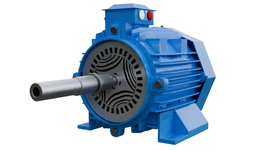
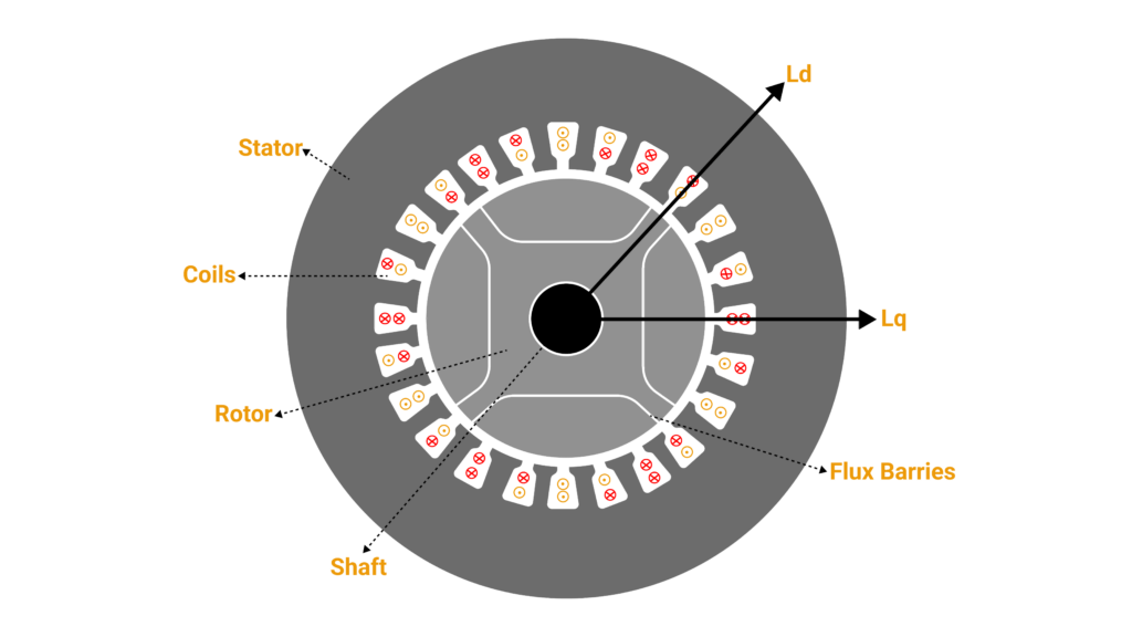
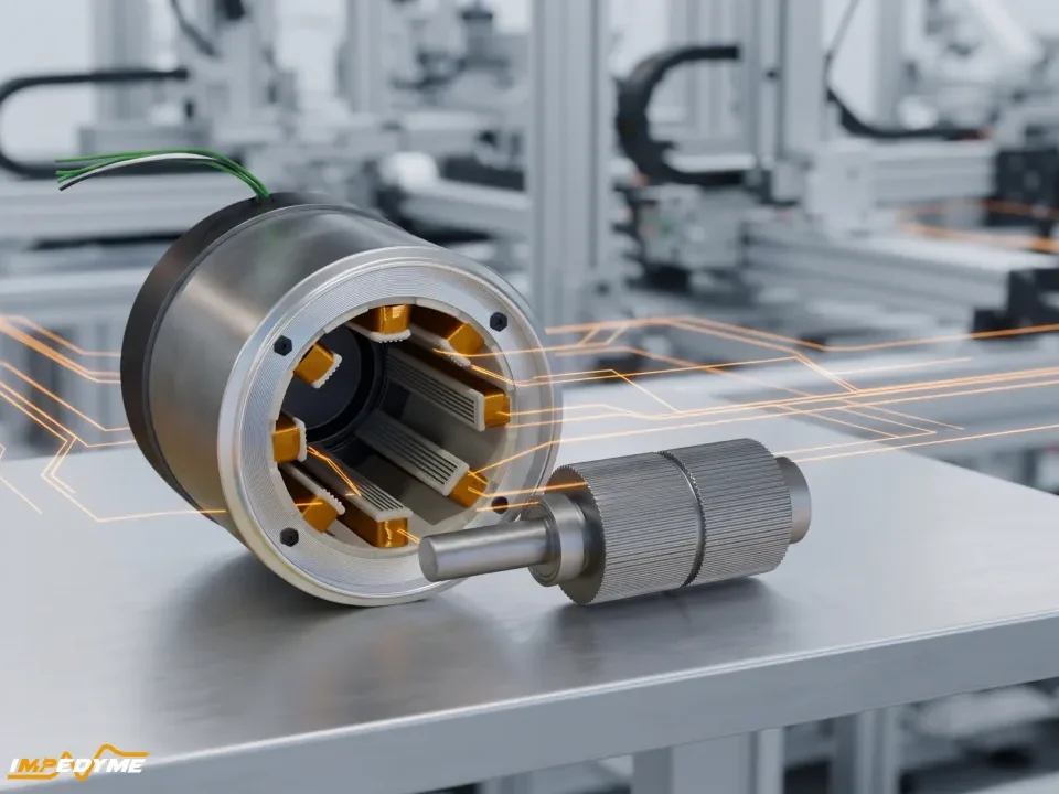
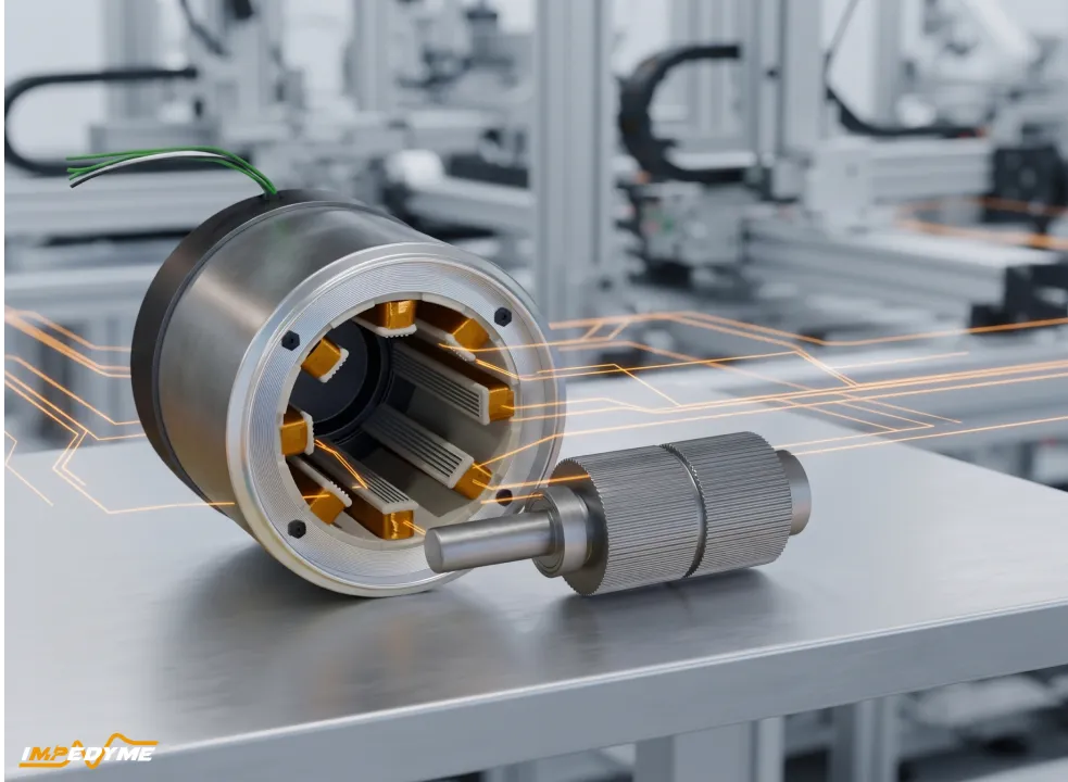
The SynRM stator is a conventional distributed three-phase winding, so existing stator tooling, insulation systems, impregnation and rewind practices apply; many manufacturers share stator stacks with induction series. Essentially all synchronous reluctance machine distinctiveness lives in the rotor lamination.
Design levers: barrier count and shape (circular, segmented, “fluid”); rib and post widths (thin to saturate and limit q-axis leakage, thick enough for centrifugal stress); air-gap length; pole count (4 industrial, 2 very high speed, 6–8 traction); skew (often one slot pitch or stepped); and mechanical integrity at speed.
The magnet-free rotor runs markedly cooler than a cage rotor. Du, Zhang, Li and Hu’s same-volume comparison in Applied Sciences (2023) found the SynRM rotor core “about 40 °C lower than that of the IM,” and its stator core about 10 °C cooler. At equal winding temperature, Boglietti, Cavagnino, Pastorelli and Vagati at Politecnico di Torino (IEEE IAS 2005) measured 10% to 25% more torque from a SynRM than from the corresponding induction motor. A 2.2/4 kW comparison by the same group found about 10–15%. The flux barriers also remove rotor mass, so a sync reluctance motor has lower inertia, which helps dynamic loads accelerate. A cooler rotor also extends bearing grease life and reduces insulation stress.
Rotor geometries compared: salient-pole, axially laminated and transversally laminated
Simple salient-pole rotors remove iron between poles. They are cheap but have low saliency (rarely above about 3.8) and high ripple—mostly historical or for teaching.
Axially laminated anisotropic (ALA) rotors, introduced by Cruickshank, Menzies and Anderson (Proceedings of the IEE, 1966), stack bent U/V steel sheets with insulating spacers. They achieve the highest saliency (unsaturated 6–20) and lowest harmonic content, but are costly, awkward to manufacture, suffer eddy losses from slot harmonics, and are weak at high peripheral speed.
Transversally laminated anisotropic (TLA) rotors use punched multi-barrier laminations stacked like an induction rotor. Saliency is somewhat lower than ALA, but they are made on standard stamping lines, skewable and mechanically integral—the industrial standard.
Barrier counts and ripple: industrial TLA rotors use 2–5 barriers per pole. Ripple falls with rotor skew (often one stator slot pitch, or stepped) and barrier-end shaping—choosing or making asymmetric the barrier-end positions so slot harmonics cancel. Published asymmetric-end optimizations reach mid-teens percent ripple unskewed; with skew, single digits are achievable.
Speed limit: at high speed flux guides hang off thin ribs and posts, and stress concentrates at rib corners.
Rule of thumb: high volume, up to a few hundred kW, standard speeds → TLA with 3–4 barriers per pole; very high speed → TLA with fewer, wider posts, 2-pole, or dual-phase/sleeved rotors; low volume, maximum saliency, modest speed → ALA; teaching → salient-pole.
Flux barriers, ribs and saturation in a synchronous reluctance machine: the real design trade-off
More and wider barriers raise saliency and torque. The catch is that the thin ribs and posts holding the rotor together also carry flux. They saturate and leak q-axis flux, which caps the gain. Thicker ribs are mechanically safer but magnetically worse, so every AC reluctance motor rotor is a compromise between the two.
- Barrier angle and end position: choosing where barriers meet the air gap relative to slot pitch—following design rules developed by Vagati and colleagues—lets slot harmonics cancel, tuning ripple in the lamination rather than in software.
- Air gap: small gaps raise Ld (torque, power factor) but increase slot harmonics, iron loss and eccentricity sensitivity.
- Steel grade: thin, high-grade non-oriented steel cuts iron loss and gives a sharp saturation knee that keeps ribs saturated at low flux.
- Dual-phase or locally heat-treated laminations: ribs and posts are made non-magnetic (e.g., by nitriding) while flux guides stay magnetic, keeping mechanical continuity without a magnetic bridge.The cost is lower saturation flux density—published dual-phase work reports about 1.5 T, versus roughly 1.9–2.0 T for conventional non-oriented silicon steel. In a US Department of Energy non-rare-earth traction program, a dual-phase SynRM reached specific power comparable to dysprosium-free rare-earth designs. Non-magnetic titanium radial ribs are another published route.